trackspot ® Bolt User Manual - High End Systems
trackspot ® Bolt User Manual - High End Systems
trackspot ® Bolt User Manual - High End Systems

Create successful ePaper yourself
Turn your PDF publications into a flip-book with our unique Google optimized e-Paper software.
<strong>trackspot</strong> <strong>®</strong> <strong>Bolt</strong><br />
<strong>User</strong> <strong>Manual</strong><br />
© Barco Lighting <strong>Systems</strong>, Inc. 2011, All Rights Reserved<br />
Information and specifications in this document are subject to change without notice. Barco Lighting <strong>Systems</strong><br />
assumes no responsibility or liability for any errors or inaccuracies that may appear in this manual.<br />
Trademarks used in this text:<br />
<strong>High</strong> <strong>End</strong> <strong>Systems</strong>, Wholehog, <strong>trackspot</strong> and Lithopatterns are registered trademarks: and Internal Effects, the<br />
<strong>High</strong> <strong>End</strong> <strong>Systems</strong> globe logo, and the Hog logo are trademarks of Barco Lighting <strong>Systems</strong>, Inc. . Belden is a<br />
registered trademark of Belden, Inc.<br />
Other trademarks and trade names may be used in this document to refer to either the entities claiming the<br />
marks and names or their products. <strong>High</strong> <strong>End</strong> <strong>Systems</strong> disclaims any proprietary interest in trademarks and<br />
trade names owned by others.<br />
<strong>trackspot</strong> <strong>Bolt</strong> <strong>User</strong> <strong>Manual</strong><br />
Version 1.0<br />
December, 2011
Contact Information<br />
U.S. and the Americas<br />
Sales Department <strong>High</strong> <strong>End</strong> <strong>Systems</strong><br />
2105 Gracy Farms Lane<br />
Austin, TX 78758 USA<br />
voice: 512.836.2242<br />
fax: 512.837.5290<br />
Toll Free: 800.890.8989<br />
Customer Service <strong>High</strong> <strong>End</strong> <strong>Systems</strong><br />
2105 Gracy Farms Lane<br />
Austin, TX 78758 USA<br />
voice: 800.890.8989<br />
fax: 512.834.9195<br />
toll free: 800.890.8989<br />
World Wide Web: http://www.highend.com<br />
ii <strong>trackspot</strong> <strong>®</strong> <strong>Bolt</strong> <strong>User</strong> <strong>Manual</strong>
Product Modification Warning<br />
<strong>High</strong> <strong>End</strong> <strong>Systems</strong> products are designed and manufactured to meet the requirements of United States and<br />
International safety regulations. Modifications to the product could affect safety and render the product noncompliant<br />
to relevant safety standards.<br />
Mise En Garde Contre La Modification Du Produit<br />
Les produits <strong>High</strong> <strong>End</strong> <strong>Systems</strong> sont conçus et fabriqués conformément aux exigences des règlements<br />
internationaux de sécurité. Toute modification du produit peut entraîner sa non conformité aux normes de<br />
sécurité en vigueur.<br />
Produktmodifikationswarnung<br />
Design und Herstellung von <strong>High</strong> <strong>End</strong> <strong>Systems</strong> entsprechen den Anforderungen der U.S. Amerikanischen und<br />
internationalen Sicherheitsvorschriften. Abänderungen dieses Produktes können dessen Sicherheit<br />
beeinträchtigen und unter Umständen gegen die diesbezüglichen Sicherheitsnormen verstoßen.<br />
Avvertenza Sulla Modifica Del Prodotto<br />
I prodotti di <strong>High</strong> <strong>End</strong> <strong>Systems</strong> sono stati progettati e fabbricati per soddisfare i requisiti delle normative di<br />
sicurezza statunitensi ed internazionali. Qualsiasi modifica al prodotto potrebbe pregiudicare la sicurezza e<br />
rendere il prodotto non conforme agli standard di sicurezza pertinenti.<br />
Advertencia De Modificación Del Producto<br />
Los productos de <strong>High</strong> <strong>End</strong> <strong>Systems</strong> están diseñados y fabricados para cumplir los requisitos de las<br />
reglamentaciones de seguridad de los Estados Unidos e internacionales. Las modificaciones al producto podrían<br />
afectar la seguridad y dejar al producto fuera de conformidad con las normas de seguridad relevantes.<br />
<strong>trackspot</strong> <strong>®</strong> <strong>Bolt</strong> <strong>User</strong> <strong>Manual</strong> iii
Important Safety Information<br />
Instructions pertaining to continued protection against fire, electric shock, and injury to persons are<br />
found throughout this manual. Please read all instructions prior to assembling, mounting, and operating<br />
this equipment.<br />
The following international caution and warning symbols appear in margins throughout this manual to highlight<br />
messages.<br />
2 m<br />
This symbol appears adjacent to Caution messages. Not<br />
heeding these messages could result in personal injury and/or<br />
damage to equipment.<br />
This symbol appears adjacent to high voltage warning<br />
messages. Not heeding these messages could result in serious<br />
personal injury.<br />
This symbol indicates the minimum focus distance from a<br />
combustible object.<br />
This symbol cautions against mounting the fixture on or near a<br />
flammable surface.<br />
This symbol indicates an explosion hazard.<br />
UV This symbol cautions against an Ultraviolet Radiation hazard.<br />
This symbol indicates that eye protection should be worn to<br />
prevent potential injury.<br />
This symbol indicates that, while operating, equipment<br />
surfaces may reach very high temperatures. Allow the fixture<br />
to cool before handling.<br />
iv <strong>trackspot</strong> <strong>®</strong> <strong>Bolt</strong> <strong>User</strong> <strong>Manual</strong>
Warranty Information<br />
Limited Warranty<br />
Unless otherwise stated, your product is covered by a three year parts and labor limited warranty. Dichroic filters<br />
and LithoPatterns <strong>®</strong> high resolution glass gobos are not guaranteed against breakage or scratches to coating. It<br />
is the owner’s responsibility to furnish receipts or invoices for verification of purchase, date, and dealer or<br />
distributor. If purchase date cannot be provided, date of manufacture will be used to determine warranty period.<br />
Returning an Item Under Warranty for Repair<br />
It is necessary to obtain a Return Material Authorization (RMA) number from your dealer or point of purchase<br />
BEFORE any units are returned for repair. The manufacturer will make the final determination as to whether or<br />
not the unit is covered by warranty. Lamps are covered by the lamp manufacturer’s warranty.<br />
A fixture must be returned in its original packaging. Any other parts returned to <strong>High</strong> <strong>End</strong> <strong>Systems</strong> must be<br />
packaged in a suitable manner to ensure the protection of such product unit or parts, and such package shall be<br />
clearly and prominently marked to indicate that the package contains returned Product units or parts and with<br />
an RMA number. Accompany all returned Product units or parts with a written explanation of the alleged problem<br />
or malfunction. Ship returned Product units or parts to: 2105 Gracy Farms Lane, Austin, TX 78758 USA.<br />
Freight<br />
Note: Freight Damage Claims are invalid for fixtures shipped in non-factory<br />
boxes and packing materials.<br />
All shipping will be paid by the purchaser. Items under warranty shall have return shipping paid by the<br />
manufacturer only in the Continental United States. Under no circumstances will freight collect shipments be<br />
accepted. Prepaid shipping does not include rush expediting such as air freight. Air freight can be sent<br />
customer collect in the Continental United States.<br />
REPAIR OR REPLACEMENT AS PROVIDED FOR UNDER THIS WARRANTY IS THE EXCLUSIVE REMEDY OF THE<br />
CONSUMER. HIGH END SYSTEMS, INC. MAKES NO WARRANTIES, EXPRESS OR IMPLIED, WITH RESPECT TO<br />
ANY PRODUCT, AND HIGH END SPECIFICALLY DISCLAIMS ANY WARRANTY OF MERCHANTABILITY OR FITNESS<br />
FOR A PARTICULAR PURPOSE. HIGH END SHALL NOT BE LIABLE FOR ANY INDIRECT, INCIDENTAL OR<br />
CONSEQUENTIAL DAMAGE, INCLUDING LOST PROFITS, SUSTAINED OR INCURRED IN CONNECTION WITH ANY<br />
PRODUCT OR CAUSED BY PRODUCT DEFECTS OR THE PARTIAL OR TOTAL FAILURE OF ANY PRODUCT<br />
REGARDLESS OF THE FORM OF ACTION, WHETHER IN CONTRACT, TORT (INCLUDING NEGLIGENCE), STRICT<br />
LIABILITY OR OTHERWISE, AND WHETHER OR NOT SUCH DAMAGE WAS FORESEEN OR UNFORESEEN.<br />
Warranty is void if the product is misused, damaged, modified in any way, or for unauthorized repairs or parts.<br />
This warranty gives you specific legal rights, and you may also have other rights which vary from state to state.<br />
<strong>trackspot</strong> <strong>®</strong> <strong>Bolt</strong> <strong>User</strong> <strong>Manual</strong> v
Patents<br />
This product may use one or more of the following patents: US 4,392,187; US 4,602,321; US 4,688,161;<br />
US 4,701,833; US 4,709,311; US 4,779,176; US 4,800,474; US 4,962,687; US 4,972,306; US 4,980,806;<br />
US 5,010,459; US 5,031,078; US 5,073,847; US 5,078,039; US 5,186,536; US 5,209,560; US 5,278,742;<br />
US 5,282,121; US 5,307,295; US 5,329,431; US 5,331,822; US 5,367,444; US 5,402,326; US 5,414,328;<br />
US 5,426,576; US 5,430,629; US 5,432,691; US 5,454,477; US 5,455,748; US 5,502,627; US 5,506,762;<br />
US 5,515,254; US 5,537,303; US 5,545,951; US 5,588,021; US 5,590,954; US 5,590,955; US 5,640,061;<br />
US 5,647,662; US 5,691,886; US 5,702,082; US 5,728,994; US 5,758,955; US 5,758,956; US 5,769,527;<br />
US 5,769,531; US 5,774,273; US 5,788,365; US 5,794,881; US 5,795,058; US 5,798,619; US 5,806,951;<br />
US 5,812,596; US 5,823,661; US 5,825,548; US 5,828,485; US 5,829,868; US 5,857,768; US 5,882,107;<br />
US 5,921,659; US 5,934,794; US 5,940,204; US 5,945,786; US 5,953,151; US 5,953,152; US 5,969,485;<br />
US 5,980,066; US 5,983,280; US 5,984,248; US 5,986,201; US 6,011,662; US 6,029,122; US 6,048,080;<br />
US 6,048,081; US 6,054,816; US 6,057,958; US 6,062,706; US 6,079,853; US 6,126,288; US 6,142,652;<br />
US 6,142,653; US 6,172,822; US 6,175,771; US 6,188,933; US 6,208,087; US 6,219,093; US 6,220,730;<br />
US 6,241,366; US 6,249,091; US 6,255,787; US 6,256,136; US 6,261,636; US 6,278,542; US 6,278,545;<br />
US 6,278,563; US 6,288,828; US 6,326,741; US 6,327,103; US 6,331,756; US 6,346,783; US 6,421,165;<br />
US 6,430,934; US 6,459,217; US 6,466,357; US 6,502,961; US 6,515,435; US 6,523,353; US 6,536,922;<br />
US 6,538,797; US 6,545,586; US 6,549,324; US 6,549,326; US 6,563,520; US 6,565,941; US 6,570,348;<br />
US 6,575,577; US 6,578,991; US 6,588,944; US 6,592,480; US 6,597,132; US 6,600,270; US 6,601,974;<br />
US 6,605,907; US 6,617,792; US 6,621,239; US 6,622,053; US 6,635,999; US 6,648,286; US 6,664,745;<br />
US 6,682,031; US 6,693,392; US 6,696,101; US 6,719,433; US 6,736,528; US 6,771,411; US 6,775,991;<br />
US 6,783,251; US 6,801,353; US 6,812,653; US 6,823,119; US 6,865,008; US 6,866,390; US 6,866,402;<br />
US 6,866,451; US 6,869,193; US 6,891,656; US 6,894,443; US 6,919,916; US 6,930,456; US 6,934,071;<br />
US 6,937,338; US 6,955,435; US 6,969,960; US 6,971,764; US 6,982,529; US 6,988,805; US 6,988,807;<br />
US 6,988,817; US 7,000,417; US 7,011,429; US 7,018,047; US 7,020,370; US 7,033,028; US 7,048,838;<br />
US 7,055,963; US 7,055,964; US 7,057,797; US 7,073,910; US 7,078,869; US 7,092,098; US 7,119,902;<br />
US 7,161,562; US 7,175,317; US 7,181,112; US 7,206,023; US 7,210,798; US D347,113; US D350,408;<br />
US D359,574; US D360,404; US D365,165; US D366,712; US D370,080; US D372,550; US D374,439;<br />
US D377,338; US D381,740; US D409,771; AT E169413; CA 2142619; CA 2145508; CA 2245842;<br />
DE 22588.4-08; DE 621495; DE 655144; DE 69320175.4; DE 69322401.0; DE 69331145.2; DE 69525856.7;<br />
DE 69734744.3; DE 797503; DK 0655144; DK 1447702; EP 0475082; EP 0621495; EP 0655144; EP 0662275;<br />
EP 0767398; EP 0797503; EP 0969247; EP 1447702; ES 0621495; FR 0621495; FR 0655144; FR 0662275;<br />
FR 1447702; GB 2043769B; GB 2055842B; GB 2283808B; GB 2290134B; GB 2291814B; GB 2292530B;<br />
GB 2292896B; GB 2294909B; GB 2295058B; GB 2303203B; GB 2306887B; GB 2307036B; GB 2316477B;<br />
IE 0621495; IT 034244BE; 2005; IT 0621495; IT 0655144; JP 3495373; JP 3793577; NL 0621495;<br />
NL 0797503; NL 0969247; UK 0621495; UK 0655144; UK 0662275; UK 0797503; UK 0969247; UK 1447702;<br />
vi <strong>trackspot</strong> <strong>®</strong> <strong>Bolt</strong> <strong>User</strong> <strong>Manual</strong>
Table of Contents<br />
<strong>trackspot</strong><strong>®</strong> <strong>Bolt</strong> <strong>User</strong> <strong>Manual</strong> ........................................................................ i<br />
Contact Information ..................................................................................... ii<br />
Product Modification Warning ........................................................................ iii<br />
Important Safety Information ....................................................................... iv<br />
Warranty Information ................................................................................... v<br />
Limited Warranty ....................................................................................... v<br />
Returning an Item Under Warranty for Repair ................................................ v<br />
Freight ..................................................................................................... v<br />
Patents ...................................................................................................... vi<br />
Chapter 1: Product Overview<br />
Features ...................................................................................................... 1<br />
Operation ................................................................................................... 1<br />
Construction ............................................................................................... 2<br />
Specifications .............................................................................................. 3<br />
Mechanical Specifications ............................................................................. 3<br />
Wheel Components ..................................................................................... 3<br />
Electrical .................................................................................................... 4<br />
Operation ................................................................................................... 4<br />
Environmental ............................................................................................ 4<br />
Cables and Connectors ................................................................................. 4<br />
Related Products and Accessories ............................................................... 5<br />
Chapter 2: Installation and Setup<br />
Unpacking the <strong>trackspot</strong><strong>®</strong> <strong>Bolt</strong> Fixture ........................................................ 7<br />
Installing the Power Cord Cap ..................................................................... 7<br />
Power Cord Cap: UK Only ............................................................................. 7<br />
VIGTIG FIKKER HEDS INFORMATION - DANMARK ............................................ 8<br />
Mounting the <strong>trackspot</strong> <strong>Bolt</strong> Fixture ............................................................ 8<br />
Standing the Fixture on its <strong>End</strong> Handles ......................................................... 9<br />
Mounting the Fixture on a Truss or Other Support System ................................ 9<br />
Truss or Other Support System................................................................... 9<br />
Safety Cable............................................................................................. 9<br />
Clamps .................................................................................................... 9<br />
Mounting Procedure.................................................................................. 10<br />
Linking <strong>trackspot</strong> <strong>Bolt</strong> Fixtures .................................................................. 11<br />
Cable Connectors ....................................................................................... 11<br />
Connecting to a DMX512 Link ...................................................................... 12<br />
<strong>trackspot</strong> <strong>®</strong> <strong>Bolt</strong> <strong>User</strong> <strong>Manual</strong> vii
Powering On the Fixture ............................................................................ 12<br />
Setting the DMX Start Channel ................................................................... 13<br />
Shutting Down the Fixture ......................................................................... 14<br />
Chapter 3: The Menu System<br />
Navigating the Menu System ...................................................................... 15<br />
The <strong>trackspot</strong> <strong>Bolt</strong> Menu Map ..................................................................... 16<br />
The <strong>trackspot</strong> <strong>Bolt</strong> Menu Options ............................................................... 18<br />
Address Menu (AddR) ................................................................................ 18<br />
Set Menu (SET) ......................................................................................... 19<br />
Setting Factory Defaults (FACT) ................................................................ 19<br />
Changing the Display Output (DSPL).......................................................... 19<br />
Inverting Pan (P/IN) ................................................................................ 19<br />
Inverting Tilt (T/IN) ................................................................................. 20<br />
Swapping Pan and Tilt (SWAP) .................................................................. 20<br />
Data Loss (DLOS).................................................................................... 20<br />
Press to store............................................................................. 20<br />
Defog Fan Mode (DEFG) ........................................................................... 21<br />
Mode Menu (MODE) ................................................................................... 22<br />
Selecting Protocol (PROT)......................................................................... 22<br />
Crossloading the Fixture (XLd) .................................................................. 22<br />
Test Menu (TEST) ...................................................................................... 23<br />
Homing the Fixture (HOME) ...................................................................... 23<br />
Lamp Test (LAMP) ................................................................................... 23<br />
Changing Boot Codes (BOOT) ................................................................... 23<br />
Performing Self Tests (SELF)..................................................................... 24<br />
Moving the Fixture to Setup Position (S/UP) ................................................ 24<br />
Information Menu (INFO) ........................................................................... 25<br />
Viewing the Current Software Version (VER) ............................................... 25<br />
Viewing the Unique Fixture ID (UNIQ) ........................................................ 25<br />
Monitoring Internal Fixture Temperature (TEMP).......................................... 25<br />
Viewing Fixture Hours .............................................................................. 26<br />
Viewing DMX Data for the Link (DATA) ....................................................... 27<br />
Viewing Lamp Hours (L/HR) ...................................................................... 27<br />
Resetting Lamp Hours (L/RS).................................................................... 27<br />
Monitoring the Fan Speed (FAN) ................................................................ 28<br />
Viewing the Current Motor and Display Versions (VER) ................................. 28<br />
viii <strong>trackspot</strong> <strong>®</strong> <strong>Bolt</strong> <strong>User</strong> <strong>Manual</strong>
Chapter 4: Fixture Programming<br />
DMX Programming Overview ..................................................................... 29<br />
Full Speed verses MSpeed Control ................................................................ 29<br />
DMX Programming Options .......................................................................... 29<br />
Programming with a DMX Console ................................................................ 29<br />
DMX Parameters for <strong>trackspot</strong> <strong>Bolt</strong> Fixtures .............................................. 30<br />
Pan and Tilt ............................................................................................... 30<br />
Static Color Wheel ..................................................................................... 31<br />
Static Color Function .................................................................................. 31<br />
Static Color Position ................................................................................... 31<br />
Static Gobo Wheel ..................................................................................... 32<br />
Static Gobo Function .................................................................................. 32<br />
Static Gobo Position ................................................................................... 32<br />
Rotating Gobo Wheel ................................................................................. 33<br />
Rotating Gobo Wheel Function ..................................................................... 33<br />
Rotating Gobo Wheel Position ...................................................................... 33<br />
Rotating Gobo Rotate Function ..................................................................... 34<br />
Rotating Gobo Rotate Coarse/Rotating Gobo Rotate Fine ................................. 34<br />
Focus ......................................................................................................... 34<br />
Iris ............................................................................................................ 34<br />
Shutter ...................................................................................................... 34<br />
Dim ............................................................................................................ 35<br />
MSpeed (Motor Speed) .............................................................................. 35<br />
Macros ....................................................................................................... 35<br />
Control Settings ......................................................................................... 36<br />
Appendix A: MSpeed Conversion Table ................................................... 37<br />
Appendix B: Important Safety Information ............................................ 39<br />
APPENDICE B: IMPORTANTES INFORMATIONS SUR LA SÉCURITÉ ..................... 40<br />
ANHANG B: WICHTIGE HINWEISE FÜR IHRE SICHERHEIT ............................... 41<br />
APÉNDICE B: INFORMACIÓN IMPORTANTE DE SEGURIDAD .............................. 42<br />
APPENDICE B: IMPORTANTI INFORMAZIONI PER LA SICUREZZA ...................... 43<br />
<strong>trackspot</strong> <strong>®</strong> <strong>Bolt</strong> <strong>User</strong> <strong>Manual</strong> ix
x <strong>trackspot</strong> <strong>®</strong> <strong>Bolt</strong> <strong>User</strong> <strong>Manual</strong>
Chapter 1:<br />
Product Overview<br />
CHAPTER 1<br />
Product Overview<br />
This chapter describes the features and specifications of the <strong>trackspot</strong> <strong>®</strong> <strong>Bolt</strong><br />
fixture along with a list of related products and accessories.<br />
The <strong>trackspot</strong> <strong>Bolt</strong> fixture features a state-of-the-art LED lighting engine outputting over 3,000<br />
lumens of pure white light in a small, fast moving mirror fixture. With rotating gobos, remote<br />
focus, anamorphic gobos and a wedged color wheel, <strong>trackspot</strong> <strong>Bolt</strong> sets a new standard for<br />
functionality in a moving mirror fixture.<br />
The LED source provides enhancements above non-LED fixtures. With no loss of output over<br />
years of use, reduced power consumption and less heat dissipation, the <strong>trackspot</strong> <strong>Bolt</strong> fixture is<br />
a perfect choice for long lasting efficiency.<br />
Utilizing new technology, every motion within the fixture is capable of high speed movement<br />
along with smooth, slow changes. The rotating lithopattern wheel has seven glass patterns all<br />
capable of indexing, rotating, and animating. The anamorphic fixed gobo wheel features seven<br />
patterns plus unique morphing transitions from pattern to pattern.<br />
Features<br />
• LED light engine with output better than a 250 MSR<br />
• Color wheel features nine colors plus open<br />
• Fixed Anamorphic Gobo wheel with seven etched positions, eight anamorphic positions plus<br />
open<br />
• Rotating Gobo wheel with seven Lithopatterns plus open<br />
• 15 degree beam angle<br />
• Remote Focus<br />
• Variable iris<br />
• Variable strobe<br />
• No lamp to change, LED source lasts over 30,000 hours<br />
• Electronic circuit design for smooth dimming<br />
Operation<br />
• 170° pan and 110° tilt movement<br />
• DMX-512 control<br />
• Auto switching Power 100V - 240V, 50/60Hz<br />
<strong>trackspot</strong> <strong>®</strong> <strong>Bolt</strong> <strong>User</strong> <strong>Manual</strong> 1
CHAPTER 1<br />
Product Overview<br />
Construction<br />
• <strong>High</strong>-resolution microstepping motor control for smooth motion<br />
• Computer-designed optical components for maximum light efficiency<br />
• Easy maintenance access<br />
• Low-noise, high-efficiency cooling system<br />
• Break-resistant mirror<br />
• 5-pin XLR connector<br />
• LED Menu System<br />
• ETL and CE compliance<br />
• Optional Roadcase<br />
• 3 year warranty<br />
2 <strong>trackspot</strong> <strong>®</strong> <strong>Bolt</strong> <strong>User</strong> <strong>Manual</strong>
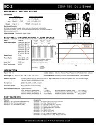
Specifications<br />
Mechanical Specifications<br />
Fixture weight (including yoke): 11.3 kg (25 lb)<br />
Shipping weight (Box + Fixture + Yoke): 17.2 kg (38 lb)<br />
CHAPTER 1<br />
Product Overview<br />
Dimensions (including yoke): 371 mm x 370 mm x 760 mm (14.6 in x 14.6 in x 29.9 in)<br />
Shipping Box Dimensions: 457 mm x 404 mm x 879 mm (18.0 in x 15.9 in x 34.6 in)<br />
Wheel Components<br />
760 mm<br />
29.9 in<br />
271 mm<br />
10.7 in<br />
Lithopatterns: Diameter: 29 mm ± .25 mm (1.142 in ± .01 in)<br />
370 mm<br />
14.6 in<br />
Image Area: 23.8 mm ± 25 mm (0.937 in ± .01 in)<br />
205 mm<br />
8.1 in<br />
371 mm<br />
14.6 in<br />
<strong>trackspot</strong> <strong>®</strong> <strong>Bolt</strong> <strong>User</strong> <strong>Manual</strong> 3
CHAPTER 1<br />
Product Overview<br />
Electrical<br />
Power consumption: 100-240V, 50/60Hz; 4.5 A<br />
Rated Lamp Life: 30.000 hrs<br />
Operation<br />
Pan: 150°<br />
Tilt: 110°<br />
Beam Angle: 15°<br />
Environmental<br />
Maximum ambient temperature: 45° C (113° F)<br />
Minimum distance to lighted object: 1 m (3.28 ft)<br />
Minimum distance to flammable objects: 1 m (3.28 ft)<br />
Cables and Connectors<br />
Warning: Class I equipment - For continued protection<br />
against electric shock connect this equipment to an<br />
earthed (grounded) power source only<br />
This equipment for connection to branch circuit<br />
having a maximum overload protection of 20 A<br />
Caution: Do not mount on a flammable surface<br />
Not for residential use<br />
Use in dry locations only<br />
Belden <strong>®</strong> 3107A or equivalent (meets specifications for EIA RS-485 applications) with the<br />
following characteristics:<br />
• Two twisted pairs plus a shield<br />
• maximum capacitance between conductors - 30 pF/ft.<br />
• maximum capacitance between conductor and shield - 55 pF/ft.<br />
• maximum resistance of 20Ω / 1000 ft.<br />
• nominal impedance 100-140Ω<br />
4 <strong>trackspot</strong> <strong>®</strong> <strong>Bolt</strong> <strong>User</strong> <strong>Manual</strong>
Related Products and Accessories<br />
<strong>trackspot</strong> <strong>Bolt</strong> LithoPatterns<br />
Name Part Number<br />
CHAPTER 1<br />
Product Overview<br />
Call Customer<br />
Service<br />
Wholehog <strong>®</strong> 3 Lighting Console 25020001<br />
Road Hog <strong>®</strong> Full Boar Lighting Console A6020001<br />
Road Hog <strong>®</strong> Lighting Console A2020001<br />
Heavy duty 5-pin XLR cable (10’) 55050017<br />
Heavy duty 5-pin XLR cable (25’) 55050018<br />
Heavy duty 5-pin XLR cable (50’) 55050019<br />
Heavy duty 5-pin XLR cable (100’) 55050020<br />
Galvanized safety cable 12040001<br />
Cheeseborough clamp 55040014<br />
Mega-Claw clamp 67040007<br />
<strong>trackspot</strong> <strong>®</strong> <strong>Bolt</strong> <strong>User</strong> <strong>Manual</strong> 5
CHAPTER 1<br />
Product Overview<br />
6 <strong>trackspot</strong> <strong>®</strong> <strong>Bolt</strong> <strong>User</strong> <strong>Manual</strong>
Chapter 2:<br />
Installation and Setup<br />
CHAPTER 2<br />
Installation and Setup<br />
Installation includes mounting, connecting to power, and setting a start<br />
channel to configure the fixture for DMX control.<br />
Unpacking the <strong>trackspot</strong> <strong>®</strong> <strong>Bolt</strong> Fixture<br />
Carefully unpack your fixture and verify that it arrived complete and without any damage. If any<br />
internal or external parts of the fixture are damaged you must notify both the shipping agent<br />
and your sales agent immediately.<br />
Do not discard the shipping carton and packing materials. The carton and packing materials<br />
are specifically designed to protect the product during transport. <strong>High</strong> <strong>End</strong> <strong>Systems</strong> assumes no<br />
responsibility for products damaged during transport. Any product being returned for repair<br />
must be shipped in its original shipping carton and packing materials.<br />
Note: Before sending anything to the factory, be sure to call your HES<br />
dealer/distributor for a Return Authorization (RA) number. The factory<br />
cannot accept any goods shipped without an RA number.<br />
Installing the Power Cord Cap<br />
The <strong>trackspot</strong> <strong>Bolt</strong> fixture ships with a US Edison connector. If your application requires a<br />
different connector, you must remove it and install the appropriate power cord cap before you<br />
connect the <strong>trackspot</strong> <strong>Bolt</strong> to a power outlet. The type of power cord cap depends on the<br />
location in which the <strong>trackspot</strong> <strong>Bolt</strong> will be used; different locations (even within the same<br />
country) might have different power cord cap requirements.<br />
Note: Because of the wide variety of power cord caps used worldwide, <strong>High</strong><br />
<strong>End</strong> <strong>Systems</strong> cannot make specific recommendations for the<br />
particular power cord cap you should use. Contact a local authority if<br />
you are unsure which type of power cord cap you need.<br />
Power Cord Cap: UK Only<br />
The cores in the mains lead are colored in accordance with the following code:<br />
• green and yellow: earth<br />
• blue: neutral<br />
• brown: live<br />
<strong>trackspot</strong> <strong>®</strong> <strong>Bolt</strong> <strong>User</strong> <strong>Manual</strong> 7
CHAPTER 2<br />
Installation and Setup<br />
Since the colors of the cores in the mains lead of this equipment may not correspond with the<br />
colored markings identifying the terminals in your plug, proceed as follows:<br />
• The core which is colored green and yellow must be connected to the terminal in the plug<br />
which is marked with the letter “E” or by the earth symbol , or colored green or green<br />
and yellow<br />
• The core which is colored blue must be connected to the terminal which is marked with the<br />
letter “N” or colored black<br />
• The core which is colored brown must be connected to the terminal which is marked with<br />
the letter “L” or colored red<br />
VIGTIG FIKKER HEDS INFORMATION - DANMARK<br />
ADVARSEI: RESKYTTEKSE MOD ELEKTRISK SHOCK<br />
VIGTIGT!<br />
LEDERE MED GROEN/GUL ISOLATION<br />
MA KUN TILSLUTTES EN KLEMME MAERKET<br />
ELLER =<br />
CAUTION: Class 1 equipment. This equipment must be earthed<br />
Mounting the <strong>trackspot</strong> <strong>Bolt</strong> Fixture<br />
1 m<br />
WARNING!<br />
Equipment suitable for dry locations only. Do not expose this<br />
equipment to rain or moisture.<br />
This equipment must be earthed.<br />
CAUTION!<br />
Always use a secondary safety cable through the yoke when<br />
mounting this fixture.<br />
Mount the fixtures and controllers in a location that is away<br />
from direct heat and protected from moisture.<br />
Maintain a minimum focus distance of 1 meter.<br />
Do not mount within 1 meter of a flammable surface.<br />
8 <strong>trackspot</strong> <strong>®</strong> <strong>Bolt</strong> <strong>User</strong> <strong>Manual</strong>
Standing the Fixture on its <strong>End</strong> Handles<br />
CHAPTER 2<br />
Installation and Setup<br />
The <strong>trackspot</strong> <strong>Bolt</strong> end handles are designed to support the weight of the fixture; however,<br />
make sure you observe the following guidelines:<br />
• The fixture must be located away from moving objects that could strike it and cause it to<br />
become unbalanced.<br />
• The fixture must be mounted on a sturdy, stable surface.<br />
• If the surface is other than floor height, make sure you use safety cables as described in the<br />
next section.<br />
Mounting the Fixture on a Truss or Other Support System<br />
WARNING!<br />
Before mounting, disconnect power to the fixture. If it has been<br />
operating, allow the fixture to cool for five minutes before handling.<br />
Truss or Other Support System<br />
If you are mounting the fixture(s) on a truss or another type of support, verify that the truss or<br />
support will handle the weight of all the devices you are mounting. The <strong>trackspot</strong> <strong>Bolt</strong> fixture<br />
with its yoke weighs 11.3 kg (25 lb).<br />
Safety Cable<br />
<strong>High</strong> <strong>End</strong> <strong>Systems</strong> strongly recommends that you use a safety cable when mounting any fixture.<br />
You must supply your own safety cable and verify that the cable is capable of supporting the<br />
weight of the fixture. You can order galvanized safety cables from your <strong>High</strong> <strong>End</strong> <strong>Systems</strong><br />
dealer/distributor (see Related Products and Accessories on page 5).<br />
Clamps<br />
You must supply the required truss clamp and make sure it is capable of supporting the weight<br />
of the fixture with the yoke. You can order truss clamps from your <strong>High</strong> <strong>End</strong> <strong>Systems</strong> dealer/<br />
distributor (see Related Products and Accessories on page 5).<br />
Make sure the fixture cannot be rotated all the way around (360°). (Using two clamps is a good<br />
way to do this). Allowing the fixture to rotate 360° could loosen the clamp mounting bolts.<br />
<strong>trackspot</strong> <strong>®</strong> <strong>Bolt</strong> <strong>User</strong> <strong>Manual</strong> 9
CHAPTER 2<br />
Installation and Setup<br />
Mounting Procedure<br />
Because of the variety of conceivable lighting designs, you should consider the procedure below<br />
as a suggested guideline only. <strong>High</strong> <strong>End</strong> <strong>Systems</strong> cannot make specific recommendations for<br />
your particular lighting design or venue.<br />
To mount the fixture:<br />
CAUTION:<br />
Always stand on a firm, stable surface to mount a <strong>trackspot</strong> <strong>Bolt</strong><br />
fixture.<br />
1. Attach a clamps using any of the three holes on the yoke. Use locking washers when<br />
attaching the clamp to the yoke<br />
2. Tighten the clamps firmly to the <strong>trackspot</strong> <strong>Bolt</strong> yoke and to the support.<br />
3. Loop one or more suitable safety cables around the support and around the <strong>trackspot</strong> <strong>Bolt</strong><br />
yoke.<br />
CAUTION:<br />
Do not use the fixture handles as a safety cable attachment<br />
point. The <strong>trackspot</strong> <strong>Bolt</strong> handles are intended only for<br />
hand-lifting the fixture.<br />
10 <strong>trackspot</strong> <strong>®</strong> <strong>Bolt</strong> <strong>User</strong> <strong>Manual</strong>
Linking <strong>trackspot</strong> <strong>Bolt</strong> Fixtures<br />
CHAPTER 2<br />
Installation and Setup<br />
The <strong>trackspot</strong> <strong>Bolt</strong> fixture operates on standard DMX512 link controlled by a DMX console. The<br />
number of fixtures on a link will be determined by the combined number of channels required by<br />
all the fixtures. A <strong>trackspot</strong> <strong>Bolt</strong> fixture requires a 21-channel footprint on a standard DMX512<br />
link.<br />
Cable Connectors<br />
Use data-grade cable and 5-pin XLR cable connectors to attach your fixture to the DMX link.<br />
The <strong>trackspot</strong> <strong>Bolt</strong> fixture accepts 5-pin XLR cable connectors. Cabling must have a male XLR<br />
connector on one end of the cable and a female XLR connector on the other end.<br />
Pin one is the common (cable shield), pin two is the data complement (negative), pin three is<br />
the data true (positive). Pins four and five are not used, but they allow a secondary data link to<br />
pass through the fixture.<br />
Common<br />
(cable shield)<br />
negative<br />
(data<br />
complement)<br />
1<br />
2<br />
3<br />
5<br />
4<br />
positive<br />
(data true)<br />
Male XLR Connector<br />
Grounding lug (inside XLR shell)<br />
positive<br />
(data true)*<br />
negative<br />
(data complement)*<br />
XLR shell<br />
positive<br />
(data true)*<br />
negative<br />
(data<br />
complement)*<br />
5 1<br />
4 2<br />
3<br />
positive<br />
(data true)<br />
Female XLR Connector<br />
*This data line is not used by the fixture, but allows data to pass through the fixture.<br />
Common<br />
(cable shield)<br />
negative<br />
(data<br />
complement)<br />
Test each cable with a voltage/ohm meter (VOM) to verify correct polarity and to make sure<br />
that the negative and positive pins are not grounded or shorted to the shield or to each other.<br />
CAUTION! Do not connect anything to the ground lug on the XLR<br />
connectors. Do not connect or allow contact between the common<br />
(cable shield) and the fixture’s chassis ground. Grounding the common<br />
could cause a ground loop and/or erratic behavior.<br />
<strong>trackspot</strong> <strong>®</strong> <strong>Bolt</strong> <strong>User</strong> <strong>Manual</strong> 11
CHAPTER 2<br />
Installation and Setup<br />
Connecting to a DMX512 Link<br />
To link one or more fixtures to a DMX controller:<br />
1. Connect the male XLR connector of a DMX Data cable to the controller’s DMX Data Out<br />
connector.<br />
2. Connect the Data cable’s female XLR connector to the Data In connector of the first (or<br />
next) fixture on the DMX link.<br />
3. Continue linking the remaining fixtures connecting a cable from the Data Out connector of<br />
each fixture to the Data In connector of the next fixture on the link.<br />
4. Terminate the link by installing a 120 ohm, 1/4 watt (minimum) terminator in the fixture’s<br />
Data Out (female) cable connector in the last fixture on each DMX link. A terminator on the<br />
last fixture of the link prevents data reflection, which can corrupt the data communication<br />
on the link.<br />
1<br />
2<br />
3<br />
5<br />
4<br />
1 20<br />
To construct a terminator:<br />
Powering On the Fixture<br />
1. Disassemble a male 5-pin XLR connector.<br />
2. Solder a 120 ohm resistor, minimum of 1/4 watt, between Pin 2<br />
and Pin 3.<br />
3. Reassemble the XLR connector.<br />
WARNING:<br />
This equipment is designed for connection to a branch circuit having<br />
a maximum overload protection of 20 A.<br />
CAUTION:<br />
Do not power on the fixture until verifying that the line cord cap is<br />
suitable for the power source in your location. For more information,<br />
see Installing the Power Cord Cap on page 7.<br />
To power on the <strong>trackspot</strong> <strong>Bolt</strong> fixture, simply connect it to a 10000V-240V AC power source.<br />
Once the fixture is connected to a power source, it automatically begins a homing procedure to<br />
verify that fixture components are functioning.<br />
12 <strong>trackspot</strong> <strong>®</strong> <strong>Bolt</strong> <strong>User</strong> <strong>Manual</strong>
Setting the DMX Start Channel<br />
CHAPTER 2<br />
Installation and Setup<br />
Each <strong>trackspot</strong> <strong>Bolt</strong> fixture requires a block of 21 consecutive channels on a 512-Channel DMX<br />
link for standard protocol.<br />
Note: A reduced protocol using 20 channels is optional if your application<br />
only requires 8-bit control of LED Dimming. You can use the menu<br />
system to change the configuration to reduced protocol, (see<br />
Selecting Protocol (PROT) on page 22).<br />
To set the Start Channel on an<br />
<strong>trackspot</strong> <strong>Bolt</strong> fixture:<br />
1. Access the fixture’s menu<br />
system via the LED display<br />
on the fixture’s front<br />
panel. For a detailed<br />
description of the menu<br />
system, see Chapter 3:<br />
The Menu System on page<br />
15.<br />
2. To unlock the menu, press<br />
and hold the <br />
button until AddR appears<br />
on the LED display. Press<br />
the button to select.<br />
MENU button unlocks<br />
the menu and backs<br />
through menu levels<br />
3. The display will show the start channel currently assigned to the fixture.<br />
4. Use the and arrow buttons to select a valid DMX start channel from 0-491.<br />
The display will flash a new option ready for selection. For more information on addressing<br />
your fixture, see Address Menu (AddR) on page 18.<br />
5. Press the button to store the new DMX Start channel. The display will stop flashing<br />
when a new option is entered.<br />
When setting the Start channel on a fixture, remember:<br />
UP and DOWN<br />
arrows scroll to<br />
a value or option<br />
ENTER button<br />
selects an option<br />
or a menu value<br />
• A fixture’s physical location on the link does not have to coincide with the order of channel<br />
range assignments in the link.<br />
• The fixture’s channel range must not overlap any other device’s channel range on the link.<br />
When two devices on the same DMX link have overlapping channel ranges, one or both<br />
devices will be disabled or behave erratically. The single exception would be if two or more<br />
fixtures need to respond to controller commands in exactly the same way. In that case,<br />
those fixtures must be the same type and must share the entire channel range.<br />
<strong>trackspot</strong> <strong>®</strong> <strong>Bolt</strong> <strong>User</strong> <strong>Manual</strong> 13
CHAPTER 2<br />
Installation and Setup<br />
Shutting Down the Fixture<br />
A DMX controller can shut down the fixture remotely with the Shutdown option in the Control<br />
Channel or you can simply disconnect from power. The <strong>trackspot</strong> <strong>Bolt</strong> fixture automatically<br />
shuts down in the event of DMX data loss longer than one minute.<br />
14 <strong>trackspot</strong> <strong>®</strong> <strong>Bolt</strong> <strong>User</strong> <strong>Manual</strong>
Chapter 3<br />
The Menu System<br />
You can use the fixture’s onboard menu system to configure and test the<br />
<strong>trackspot</strong> <strong>Bolt</strong> fixture.<br />
The onboard <strong>trackspot</strong> <strong>Bolt</strong> menu system allows you to:<br />
• Assign a DMX start channel.<br />
• Access fixture options such as homing the fixture, viewing fixture status, and performing<br />
self tests.<br />
• View all DMX values on the link.<br />
• Identify fixture errors.<br />
Navigating the Menu System<br />
After homing, The LED screen will display HES, BOLT, the software version in the form V<br />
Major.minor (V1.1 for example), the DMX address in the C### format, and, if the defog fan is<br />
running, DEFG.<br />
You can access and navigate the<br />
menu system via the four menu<br />
navigation buttons on the<br />
fixture’s front panel.<br />
The LED display shows the menu<br />
items you select from the menu<br />
map. When accessing fixture<br />
options, the display will flash<br />
when a new option is selected<br />
(by pressing the or<br />
arrow buttons), and<br />
stops flashing when a new<br />
option is stored (by pressing the<br />
button).<br />
MENU button unlocks<br />
the menu and backs<br />
through menu levels<br />
UP and DOWN<br />
arrows scroll to<br />
a value or option<br />
ENTER button<br />
selects an option<br />
or a menu value<br />
To access the menu system: press and hold the button until AddR appears on the<br />
display. The menu system is protected against inadvertent menu changes by requiring the<br />
button to be held for a few seconds before allowing entry to the menu system.<br />
To return to the previous option or menu without changing the value: press the<br />
button.<br />
<strong>trackspot</strong> <strong>®</strong> <strong>Bolt</strong> <strong>User</strong> <strong>Manual</strong> 15
CHAPTER 3<br />
The Menu System<br />
The <strong>trackspot</strong> <strong>Bolt</strong> Menu Map<br />
Level 1 Level 2 Level 3 Level 4 Option Description<br />
ADDR C### Change the existing DMX start channel<br />
SET<br />
MODE<br />
FACT<br />
DSPL<br />
P/IN<br />
T/IN<br />
SWAP<br />
DLOS<br />
DEFG<br />
PROT<br />
XLd<br />
ON Set factory defaults on<br />
OFF Set factory defaults off<br />
ON Set the LED display on<br />
OFF Set the LED display off<br />
ON Set pan invert on<br />
OFF Set pan invert off<br />
ON Set tilt invert on<br />
OFF Set tilt invert off<br />
ON Set pan/tilt swap on<br />
OFF Set pan/tilt swap off<br />
SHRT<br />
Turns LED lamp off one second after DMX data<br />
is lost.<br />
LONG<br />
Retains LED lamp state after DMX data is lost<br />
until the unit is shutdown<br />
MOD1<br />
Defog fan runs @ 12V for 3 hours after<br />
shutdown (factory default).<br />
MOD2 Defog fan runs @ 20V after shutdown<br />
MOD3<br />
Defog fan runs @ 12V during operation and 3<br />
hours after shutdown<br />
MOD4<br />
Defog fan runs @ 20V during operation and<br />
after shutdown<br />
MOD5 No defog fan operation<br />
STD Selects Standard protocol (factory default)<br />
RED Selects Reduced protocol<br />
YES Crossloads to other <strong>trackspot</strong> <strong>Bolt</strong> fixtures<br />
NO Crossload function off<br />
16 <strong>trackspot</strong> <strong>®</strong> <strong>Bolt</strong> <strong>User</strong> <strong>Manual</strong>
CHAPTER 3<br />
The Menu System<br />
Level 1 Level 2 Level 3 Level 4 Option Description<br />
HOME HOLD Homes the fixture when hold is selected<br />
LAMP<br />
ON<br />
OFF<br />
<strong>Manual</strong>ly turns the LED light engine on<br />
<strong>Manual</strong>ly turns the LED light engine off<br />
NO Default safe mode<br />
BOOT<br />
YES<br />
DONE<br />
EMTY<br />
Indicates that boot copy has been performed<br />
and begins homing fixture<br />
indicates that spare boot is empty. Perform an<br />
upload to copy boot<br />
TEST<br />
PAN<br />
TILT<br />
PAN TESTING<br />
TILT TESTING<br />
Mirror movement function<br />
DIM DIM TESTING Shutter strobe movement<br />
SELF<br />
(Note 1)<br />
COLR<br />
LT1<br />
LT1R<br />
COLOR TESTING<br />
GOBO 1 TESTING<br />
GOBO ROT TESTING<br />
Static color wheel function<br />
Rotating Gobo Wheel: wheel movement<br />
Rotating Gobo Wheel: rotating gobo movement<br />
LT2 GOBO 2 TESTING Static Gobo Wheel movement<br />
IRIS IRIS TESTING Tests Iris function<br />
FCUS FOCUS TESTING Focus lens range<br />
S/UP<br />
OFF<br />
ON<br />
Setup mode for mechanical homing<br />
VER ####<br />
Shows the version of software currently loaded<br />
on the fixture<br />
UNIQ ######## Shows the fixture’s unique ID number<br />
CURR ####<br />
Shows the current temperature of the LED<br />
lighting engine.<br />
MAX ####<br />
Shows the maximum temperature of the LED<br />
lighting engine since last reset.<br />
TEMP<br />
MIN ####<br />
Shows the minimum temperature of the LED<br />
lighting engine since last reset.<br />
HOLD When you select Yes and HOLD, Max and Min<br />
INFO<br />
RST YES<br />
DONE<br />
temperature readings reset to Current. DONE<br />
displays when reset is complete.<br />
F/HR #### Shows number of fixture hours<br />
DMX 1-512 ####<br />
Shows the DMX data for the selected DMX<br />
channel on the link.<br />
L/HR #### Shows LED light engine hours<br />
L/RS<br />
NO<br />
YES DONE<br />
Select Yes to reset LED hours to zero. DONE<br />
displays when reset is complete.<br />
FAN<br />
On<br />
ERR<br />
Shows the rotations per second of the two fans<br />
located in the lamp power supply compartment<br />
M/VR<br />
MOTR<br />
DISP<br />
####<br />
####<br />
Shows Motor HW.SW version<br />
Shows LED display HW.SW version<br />
<strong>trackspot</strong> <strong>®</strong> <strong>Bolt</strong> <strong>User</strong> <strong>Manual</strong> 17
CHAPTER 3<br />
The Menu System<br />
The <strong>trackspot</strong> <strong>Bolt</strong> Menu Options<br />
The sections below explain how to access the fixture options shown in the fixture’s menu map.<br />
This manual uses the following conventions in the descriptions for menus and menu navigation<br />
buttons:<br />
Example Meaning<br />
<br />
Press the appropriate LED display navigation button on the fixture. For example, the<br />
button on the LED display panel.<br />
Menu Option<br />
Italics are used to indicate the appropriate menu selection you should choose from the<br />
on-board menu system. For example, the AddR menu option.<br />
Address Menu (AddR)<br />
The DMX Start Channel is the first channel of a device’s channel range on a DMX link and<br />
identifies the fixture for the DMX controller. There are 512 available channels on each DMX<br />
universe divided among all the devices in a particular universe. A device must have a unique<br />
DMX Start Channel number in order to respond independently to controller commands. You<br />
must assign a DMX start channel to every fixture on the link.<br />
The Address menu allows you to change the DMX start channel that is currently assigned to the<br />
fixture. The fixture’s DMX channel range must not overlap any other device’s channel range on<br />
the link. When two devices on the same DMX universe have overlapping channel ranges, one or<br />
both devices will be disabled or behave erratically.<br />
Note: The single exception would be if two or more fixtures need to respond to<br />
controller commands in exactly the same way. In that case, those fixtures<br />
must be the same type and must share the entire channel range.<br />
The <strong>trackspot</strong> <strong>Bolt</strong> fixture requires a unique range of 21 channels on the DMX link for standard<br />
protocol. The last valid Start Channel on a DMX512 link is 491.<br />
To set the DMX start channel:<br />
1. Press and hold until AddR appears on the LED display. Press to select.<br />
2. Select a new DMX start channel. The LED display flashes when a new start channel is<br />
selected.<br />
3. Press to accept the new DMX start channel. The LED display stops flashing when a<br />
new option is entered. If you do not press , the new option you selected is not<br />
stored.<br />
18 <strong>trackspot</strong> <strong>®</strong> <strong>Bolt</strong> <strong>User</strong> <strong>Manual</strong>
Set Menu (SET)<br />
Setting Factory Defaults (FACT)<br />
CHAPTER 3<br />
The Menu System<br />
When you set this menu item on, all factory options return to their default settings. <strong>trackspot</strong><br />
<strong>Bolt</strong> fixtures are shipped from the factory with the following default option settings:<br />
pan/tilt swap = off<br />
tilt invert = off<br />
The factory default menu option displays On if all the factory options are at the factory default<br />
settings. If any of the items listed above are not at the factory default setting, the display reads<br />
OFF. Selecting the OFF option will have no effect. To restore the factory default setting:<br />
1. Press and hold until AddR appears on the LED display.<br />
2. Scroll to the SET menu. Press to select.<br />
3. Scroll to the FACT menu (this will be the first menu displayed). Press .<br />
4. Scroll to ON to restore the factory option defaults.<br />
5. Press to store.<br />
Changing the Display Output (DSPL)<br />
You can manually turn the fixture’s LED display on or off. If you want to remotely change the<br />
display output (using a DMX console), see Control Settings on page 36.<br />
To turn the display off:<br />
1. Press and hold until AddR appears on the LED display.<br />
2. Scroll to the SET menu. Press to select.<br />
3. Scroll to the DSPL menu. Press to select.<br />
4. Scroll to ON to set the LED display to normal intensity.<br />
5. Press to store.<br />
Inverting Pan (P/IN)<br />
This menu item inverts the direction of the pan motor, to allow fixtures mounted opposite each<br />
other horizontally to respond to pan movement commands in the same direction.<br />
To invert the fixture’s pan motion:<br />
1. Press and hold until AddR appears on the LED display.<br />
2. Scroll to the SET menu. Press to select.<br />
3. Scroll to the P/IN menu. Press to select.<br />
4. Scroll to ON to invert the fixture’s pan motion, or OFF to return the fixture’s pan motion to<br />
normal orientation.<br />
5. Press to store.<br />
pan invert = off<br />
LED display = on and bright<br />
LED off with DMX data loss = short<br />
protocol = STD (standard)<br />
<strong>trackspot</strong> <strong>®</strong> <strong>Bolt</strong> <strong>User</strong> <strong>Manual</strong> 19
CHAPTER 3<br />
The Menu System<br />
Inverting Tilt (T/IN)<br />
This menu item inverts the direction of the tilt motor, to allow fixtures mounted opposite each<br />
other vertically to respond to tilt movement commands in the same direction.<br />
To invert the fixture’s tilt motion:<br />
1. Press and hold until AddR appears on the LED display.<br />
2. Scroll to the SET menu. Press to select.<br />
3. Scroll to the T/IN menu. Press to select.<br />
4. Scroll to ON to invert the fixture’s tilt motion, or OFF to return the fixture’s tilt motion to<br />
normal orientation.<br />
5. Press to store.<br />
Swapping Pan and Tilt (SWAP)<br />
This menu option swaps the pan motor and tilt motor operation to allow fixtures hung<br />
perpendicular to each other to respond to pan and tilt movement commands in the same<br />
direction.<br />
To swap pan and tilt motion:<br />
1. Press and hold until AddR appears on the LED display.<br />
2. Scroll to the SET menu. Press to select.<br />
3. Scroll to the SWAP menu. Press to select.<br />
4. Scroll to ON to swap the fixture’s pan and tilt motion, or OFF to return the fixture’s pan and<br />
tilt motion to normal orientation.<br />
5. Press to store.<br />
Data Loss (DLOS)<br />
Use this menu item to determine how the fixture will react in the event of DMX data loss by<br />
turning off the LED light engine upon Data Loss or keeping the LED light engine on until shut<br />
down.<br />
To select a data loss option:<br />
1. Press and hold until AddR appears on the LED display.<br />
2. Scroll to the SET menu. Press to select.<br />
3. Scroll to the dLOS menu. Press to select.<br />
4. Scroll to LONG to turn the LED light engine off only when the fixture is shut down, or SHRT<br />
to turn off the LED light engine one second after data loss.<br />
Press to store.<br />
20 <strong>trackspot</strong> <strong>®</strong> <strong>Bolt</strong> <strong>User</strong> <strong>Manual</strong>
Defog Fan Mode (DEFG)<br />
CHAPTER 3<br />
The Menu System<br />
The <strong>trackspot</strong> <strong>Bolt</strong> features a fan inside the fixture that blows air across the inside of the output<br />
lens to clear fog(atmospheres) condensation. You can choose from four different modes plus off<br />
to control the Defog fan operation depending on your application’s requirement:<br />
To turn the defog fan off:<br />
MOD1 Defog fan runs @ 12V for 3 hours after shutdown (factory default).<br />
MOD2 Defog fan runs @ 20V after shutdown<br />
MOD3 Defog fan runs @ 12V during operation and 3 hours after shutdown<br />
MOD4 Defog fan runs @ 20V during operation and after shutdown<br />
MOD5 No defog fan operation<br />
1. Press and hold until AddR appears on the LED display.<br />
2. Scroll to the SET menu. Press to select.<br />
3. Scroll to the dEFG menu. Press to select.<br />
4. Scroll to MOD5 to turn the fan off.<br />
5. Press to store.<br />
<strong>trackspot</strong> <strong>®</strong> <strong>Bolt</strong> <strong>User</strong> <strong>Manual</strong> 21
CHAPTER 3<br />
The Menu System<br />
Mode Menu (MODE)<br />
Selecting Protocol (PROT)<br />
You can select between Standard protocol that provides 16-bit dimming control or Reduced<br />
protocol with 8-bit dimming control. The <strong>trackspot</strong> <strong>Bolt</strong> fixture ships with standard protocol as<br />
the default<br />
To select Reduced protocol:<br />
1. Hold until the display changes to AddR.<br />
2. Using the up and down buttons, scroll to the MOdE field and press .<br />
3. Using the up and down buttons, scroll to the PROT field and press .<br />
4. Scroll to RED to set the fixture to reduced protocol.<br />
5. Press to store.<br />
Crossloading the Fixture (XLd)<br />
The <strong>trackspot</strong> <strong>Bolt</strong> fixture can crossload software from one fixture to additional <strong>trackspot</strong> <strong>Bolt</strong><br />
fixtures on the same link.<br />
To crossload software:<br />
1. Disconnect the data cable between the console and the first fixture.<br />
2. Hold on the master fixture (the fixture with the latest software version) until the<br />
display changes to AddR.<br />
3. Using the up and down buttons, scroll to the MOdE field and press .<br />
4. Using the up and down buttons, scroll to the XLd field and press . The master<br />
fixture will upload its software to all connected fixtures on the link. The slave fixtures will<br />
display UPLd during the process. After the fixtures have completed the upload, they will<br />
reset and home.<br />
5. Notes:If the fixture(s) take longer than one minute to reset after an upload, turn off the<br />
fixture(s) and repeat the procedure. If a new boot code was included with the latest<br />
software, you will need to store the boot code on each fixture. Refer to “Changing Boot<br />
Codes” on page 3-9.<br />
22 <strong>trackspot</strong> <strong>®</strong> <strong>Bolt</strong> <strong>User</strong> <strong>Manual</strong>
Test Menu (TEST)<br />
CHAPTER 3<br />
The Menu System<br />
The Test menu allows you to manually home the fixture and perform fixture self tests to<br />
determine the origin of mechanical problems.<br />
Homing the Fixture (HOME)<br />
This menu item allows you to manually home the fixture. To remotely home the fixture using a<br />
DMX console, see Control Settings on page 36. To manually home the fixture:<br />
1. Press and hold until AddR appears on the LED display.<br />
2. Scroll to the TEST menu. Press to select.<br />
3. Scroll to the HOME option (this will be the first option displayed).<br />
4. Press to select.<br />
5. HOLD will be displayed.<br />
6. Press to select. The fixture will begin homing.<br />
Lamp Test (LAMP)<br />
The Lamp Test menu let you manually turn the LED light engine on or off. To access the lamp<br />
function:<br />
1. Hold until the display changes to AddR.<br />
2. Using the up and down buttons, scroll to the TEST field and press to select.<br />
3. Using the up and down buttons, scroll to the LAMP field and press .<br />
4. Using the up and down buttons, scroll to ON or OFF.<br />
5. Press to store.<br />
Changing Boot Codes (BOOT)<br />
When the <strong>trackspot</strong> <strong>Bolt</strong> fixture is uploaded, occasionally it is necessary to include a new boot<br />
code with the latest software. This is apparent when bOOT dIff appears in the display. To accept<br />
and store the new boot code:<br />
1. Hold until the display changes to AddR.<br />
2. Using the up and down buttons, scroll to the TEST field and press .<br />
3. Using the up and down buttons, scroll to the bOOT field and press . The fixture<br />
will display dONE, RST, and home.<br />
Caution: Do not remove power from the fixture during the<br />
above procedure.<br />
<strong>trackspot</strong> <strong>®</strong> <strong>Bolt</strong> <strong>User</strong> <strong>Manual</strong> 23
CHAPTER 3<br />
The Menu System<br />
Performing Self Tests (SELF)<br />
The following self tests are available:<br />
Parameter Self-Test Description<br />
PAN Moves through the entire pan range<br />
TILT Moves through the entire tilt range<br />
DIM Tests LED Dimming function<br />
COLR Static color wheel function<br />
LT1 Rotating Gobo wheel movement<br />
LT1R Rotating Gobo wheel: rotating gobo movement<br />
LT2 Static Gobo wheel movement<br />
IRIS Tests Iris function<br />
FCUS Moves through the Focus range<br />
To start a self test process:<br />
1. Press and hold until AddR appears on the LED display.<br />
2. Scroll to the TEST menu. Press to select.<br />
3. Scroll to the SELF menu. Press to select.<br />
4. Scroll to the desired option (listed above).<br />
5. Press to start the test. The fixture will perform the selected self test.<br />
6. Press to exit the test.<br />
Moving the Fixture to Setup Position (S/UP)<br />
Caution: The setup position is used only by qualified service<br />
personnel during maintenance.<br />
To place the fixture in setup position before servicing:<br />
1. Hold until the display changes to AddR.<br />
2. Using the up and down buttons, scroll to the TEST field and press .<br />
3. Using the up and down buttons, scroll to the S/UP field and press . The display will<br />
indicate SET NOW while the motors are electronically locked into place.<br />
4. Perform the appropriate maintenance procedures.<br />
5. Press to reset and home the fixture.<br />
24 <strong>trackspot</strong> <strong>®</strong> <strong>Bolt</strong> <strong>User</strong> <strong>Manual</strong>
Information Menu (INFO)<br />
The Information menu allows you to view current fixture information such as internal<br />
temperature, fixture hours, software version, and DMX data.<br />
Viewing the Current Software Version (VER)<br />
CHAPTER 3<br />
The Menu System<br />
This menu options lets you check the fixture’s software versions. The latest software is always<br />
available for download from www.highend.com.<br />
To view the version of software currently loaded on the fixture:<br />
1. Press and hold until AddR appears on the LED display.<br />
2. Scroll to the INFO menu. Press to select.<br />
3. Scroll to the VER option.<br />
4. Press . The LED will display the fixture’s current software version.<br />
Viewing the Unique Fixture ID (UNIQ)<br />
To view the fixture’s identification number:<br />
1. Press and hold until AddR appears on the LED display.<br />
2. Scroll to the INFO menu. Press to select.<br />
3. Scroll to the UNIQ option.<br />
4. Press . The LED will display the fixture’s unique ID number.<br />
Note: This option also contains the commands for setting the ID number for<br />
the first time at the factory. In that case UP and DOWN will be<br />
displayed as the number is generated.<br />
Monitoring Internal Fixture Temperature (TEMP)<br />
The <strong>trackspot</strong> <strong>Bolt</strong> menu system lets you monitor the internal fixture temperature. You can view<br />
the current, maximum and minimum temperatures or reset the maximum and minimum<br />
temperature readings to the current temperature.<br />
To view the fixture’s current internal temperature:<br />
1. Hold until the display changes to AddR.<br />
2. Using the up and down buttons, scroll to the INFO field and press .<br />
3. Using the up and down buttons, scroll to the TEMP field and press .<br />
4. Using the up and down buttons, scroll to the CURR field and press .<br />
The fixture will display the current internal temperature followed by C (degrees centigrade).<br />
<strong>trackspot</strong> <strong>®</strong> <strong>Bolt</strong> <strong>User</strong> <strong>Manual</strong> 25
CHAPTER 3<br />
The Menu System<br />
To view the fixture’s minimum internal temperature (lowest ambient at power on):<br />
1. Hold until the display changes to AddR.<br />
2. Using the up and down buttons, scroll to the INFO field and press .<br />
3. Using the up and down buttons, scroll to the TEMP field and press .<br />
4. Using the up and down buttons, scroll to the MIN field and press .<br />
The fixture will display the minimum internal temperature followed by C (degrees<br />
centigrade).<br />
To view the fixture’s maximum internal temperature (since the last reset):<br />
1. Hold until the display changes to AddR.<br />
2. Using the up and down buttons, scroll to the INFO field and press .<br />
3. Using the up and down buttons, scroll to the TEMP field and press .<br />
4. Using the up and down buttons, scroll to the MAX field and press .<br />
The fixture will display the maximum internal temperature followed by C (degrees<br />
centigrade) for the CPU and the LPS locations.<br />
To reset the minimum and maximum temperature readings:<br />
1. Hold until the display changes to AddR.<br />
2. Using the up and down buttons, scroll to the INFO field and press .<br />
3. Using the up and down buttons, scroll to the TEMP field and press .<br />
4. Using the up and down buttons, scroll to the RST field and press . The display<br />
flashes YES until is pressed, then displays HOLD while resetting and DONE after<br />
resetting the maximum and minimum temperatures to the current internal temperature at<br />
the CPU and LPS locations.<br />
Viewing Fixture Hours<br />
To view the time a fixture has spent turned on:<br />
1. Hold until the display changes to AddR.<br />
2. Using the up and down buttons, scroll to the INFO field and press .<br />
3. Using the up and down buttons, scroll to the F/HR field and press . The fixture will<br />
display the total fixture hours.<br />
Note: The display will indicate Hxxx for hours and M xx for minutes until<br />
H999. When fixture hours exceed 999, the display will no longer<br />
indicate minutes, instead it will use all four digits to display hours. If<br />
the display indicates OVER, the counter has rolled over 9999 hours<br />
and must be manually reset.<br />
26 <strong>trackspot</strong> <strong>®</strong> <strong>Bolt</strong> <strong>User</strong> <strong>Manual</strong>
Viewing DMX Data for the Link (DATA)<br />
CHAPTER 3<br />
The Menu System<br />
This procedure allows you to use a <strong>trackspot</strong> <strong>Bolt</strong> fixture to view DMX channel values all devices<br />
on the DMX link. Use this menu option to:<br />
• Checking current DMX values on this fixture<br />
• Test devices that do not have built-in DMX diagnostics<br />
• Check fixtures that are physically inconvenient to monitor directly<br />
If you experience a problem with a device on the link, use this menu to select a DMX channel in<br />
the device’s channel range and view its DMX value. After noting the value of the channel you<br />
selected, use your DMX console to change that channel’s value.<br />
If the value of the DMX channel you selected does not change, there may be a problem with the<br />
DMX cable or your transmitting device (i.e. DMX console).<br />
If the DMX channel value changes, but the device does not respond, the device may be faulty.<br />
Consult the documentation provided with that device for more information.<br />
To view DMX data for any device on the DMX link:<br />
1. Press and hold until AddR appears on the LED display.<br />
2. Scroll to the INFO menu. Press to select.<br />
3. Scroll to the dMX menu. Press to select.<br />
4. Scroll to the desired DMX channel (001 – 512). Channel numbers will flash.<br />
5. Press The DMX value for the selected channel will be displayed.<br />
Viewing LED Hours (L/HR)<br />
To view the number of hours the LED light engine has spent on since the last reset:<br />
1. Hold until the display changes to AddR.<br />
2. Using the up and down buttons, scroll to the INFO field and press .<br />
3. Using the up and down buttons, scroll to the L/HR field and press to view the LED<br />
hours.<br />
Note: If the display indicates OVER, the counter has rolled over 9999 hours.<br />
Resetting LED Hours (L/RS)<br />
To reset LED light engine hours:<br />
1. Hold until the display changes to AddR.<br />
2. Using the up and down buttons, scroll to the INFO field and press .<br />
3. Using the up and down buttons, scroll to the L/RS field and hold until the fixture<br />
resets the lamp hours to 0000. DONE displays when the reset is complete.<br />
<strong>trackspot</strong> <strong>®</strong> <strong>Bolt</strong> <strong>User</strong> <strong>Manual</strong> 27
CHAPTER 3<br />
The Menu System<br />
Monitoring the Fan Speed (FAN)<br />
To monitor the lamp power supply fan speed:<br />
1. Hold until the display changes to AddR.<br />
2. Using the up and down buttons, scroll to the INFO field and press .<br />
3. Using the up and down buttons, scroll to the FAN field and hold .<br />
4. Using the up and down buttons, scroll to the On to view the rotations per second of the<br />
lamp power supply fan. ERR will display if the fan is not running.<br />
Viewing the Current Motor and Display Versions (VER)<br />
This menu options shows you the currently loaded motor and LED display firmware.<br />
To view the current version:<br />
1. Press and hold until AddR appears on the LED display.<br />
2. Using the up and down buttons, scroll to the INFO menu and press to select.<br />
3. Using the up and down buttons, scroll to the M/VR option and press to select.<br />
4. Scroll to MOTR to view the motor version or DISP and press to view the current<br />
version.<br />
28 <strong>trackspot</strong> <strong>®</strong> <strong>Bolt</strong> <strong>User</strong> <strong>Manual</strong>
Chapter 4:<br />
Fixture Programming<br />
The <strong>trackspot</strong> <strong>Bolt</strong> fixture can be programmed to provide a hard edge<br />
beam with multiple colors, gobo patterns and effects.<br />
DMX Programming Overview<br />
A parameter is a fixture attribute that can be controlled to modify the light beam in terms of<br />
color, beam quality and pattern, intensity, or focus (position). DMX programming assigns a DMX<br />
value to each of the fixture’s parameters. A look (sometimes referred to a scene or a cue) is one<br />
combination of parameter settings. These looks are the building blocks for show creation.<br />
Full Speed verses MSpeed Control<br />
Some parameters can be set to operate at full speed or MSpeed (motor speed). Full speed<br />
operations are completed in the shortest length of time after the motor starts moving. With<br />
MSpeed control, change occurs smoothly over the entire MSpeed time value selected. For<br />
example, if you select an MSpeed time of 30 seconds, the motor will gradually change position<br />
until it reaches its new destination at the end of 30 seconds.<br />
DMX Programming Options<br />
Using a DMX controller, you can program an unlimited number of looks and retain direct control<br />
over the <strong>trackspot</strong> <strong>Bolt</strong> fixture at all times.<br />
Programming with a DMX Console<br />
Wholehog <strong>®</strong> lighting consoles; and Hog <strong>®</strong> 3PC software are available from <strong>High</strong> <strong>End</strong> <strong>Systems</strong> to<br />
control <strong>trackspot</strong> <strong>Bolt</strong> fixtures (see Related Products and Accessories on page 5). For<br />
information on whether your DMX controller supports <strong>trackspot</strong> <strong>Bolt</strong> fixtures, contact the<br />
controller’s vendor. For information on operating your fixture with a controller (or control device<br />
such as DMX control software), consult the documentation provided with the controller.<br />
<strong>trackspot</strong> <strong>®</strong> <strong>Bolt</strong> <strong>User</strong> <strong>Manual</strong> 29
CHAPTER 4<br />
Fixture Programming<br />
DMX Parameters for <strong>trackspot</strong> <strong>Bolt</strong> Fixtures<br />
DMX console libraries define parameters for the following <strong>trackspot</strong> <strong>Bolt</strong> functions over a<br />
21-channel range (Standard protocol) or 20-channel range (Reduced protocol). DMX libraries<br />
are copyrighted and available in <strong>High</strong> <strong>End</strong> <strong>Systems</strong> consoles.<br />
For more information on developing libraries for DMX consoles from other manufacturers,<br />
contact <strong>High</strong> <strong>End</strong> <strong>Systems</strong>.<br />
Pan and Tilt<br />
Standard Protocol Channel<br />
Channel Function Channel Function<br />
1<br />
2<br />
Pan<br />
1<br />
2<br />
Pan<br />
3<br />
4<br />
Tilt<br />
3<br />
4<br />
Tilt<br />
5 Static Color Function 5 Static Color Function<br />
6 Static Color Position 6 Static Color Position<br />
7 Static Gobo Function 7 Static Gobo Function<br />
8 Static Gobo Position 8 Static Gobo Position<br />
9 Rotating Gobo Function 9 Rotating Gobo Function<br />
10 Rotating Gobo Position 10 Rotating Gobo Position<br />
11 Rotating Gobo Rotate Function 11 Rotating Gobo Rotate Function<br />
12<br />
13<br />
Rotating Gobo Rotate<br />
12<br />
13<br />
Rotating Gobo Rotate<br />
14 Focus 14 Focus<br />
15 Iris 15 Iris<br />
16 Shutter 16 Shutter<br />
17<br />
18<br />
Dim<br />
17<br />
18<br />
Dim<br />
MSpeed<br />
19 MSpeed 19 Macro<br />
20 Macro 20 Control<br />
21 Control<br />
The Pan and Tilt parameters control the <strong>trackspot</strong> <strong>Bolt</strong> fixture’s 150° pan range and 110° tilt<br />
range. Pan and Tilt functions each utilize two channels to provide 16 bit adjustment to a fraction<br />
of a degree.<br />
Pan and Tilt motion can be controlled with MSpeed values, (see MSpeed (Motor Speed) on page<br />
35). If you choose to use MSpeed for color or gobo changes without affecting Pan and Tilt<br />
parameters, set Pan/Tilt MSpeed OFF in the Control parameter.<br />
30 <strong>trackspot</strong> <strong>®</strong> <strong>Bolt</strong> <strong>User</strong> <strong>Manual</strong>
Static Color Wheel<br />
Static Color Function<br />
This parameter provides options for how you control the color selection:<br />
Static Color Function Description<br />
CHAPTER 4<br />
Fixture Programming<br />
Indexed Takes the quickest path and snaps to the chosen color on the wheel.<br />
Forward Spin Spins the wheel forward through the colors at variable speeds.<br />
Reverse Spin Spins the wheel in reverse through the colors at variable speeds.<br />
Continuous Rotates the wheel to any position within 360°<br />
Slow Scan Performs a scan of one static color position from each side at a slow rate<br />
Fast Scan Performs a scan of one static color position from each side at a fast rate<br />
Random Selects random static color positions at variable speeds.<br />
Blink Closes and opens the shutter between indexed static color changes.<br />
You can select either full speed or MSpeed (MSpeed control of the wheel motor) mode to control<br />
the motor speed of the function you choose. For more information on MSpeed, See MSpeed<br />
(Motor Speed) on page 35.<br />
Static Color Position<br />
This parameter lets you select one of nine dichroic colors, or open Static Color Wheel.<br />
1<br />
Position Description<br />
1 Open<br />
2 Red<br />
3 Yellow<br />
4 Indigo<br />
5 Dark Magenta<br />
6 Cyan<br />
7 Green<br />
8 Amber<br />
9 Pink<br />
10 Dark Blue<br />
9<br />
8<br />
10<br />
7<br />
<strong>trackspot</strong> <strong>®</strong> <strong>Bolt</strong> <strong>User</strong> <strong>Manual</strong> 31<br />
6<br />
2<br />
5<br />
3<br />
4
CHAPTER 4<br />
Fixture Programming<br />
Static Gobo Wheel<br />
Static Gobo Function<br />
This parameter provides options for how you control the wheelspin and gobo selection on the<br />
Static Gobo Wheel.<br />
Static Gobo Function Description<br />
Indexed Takes the quickest path and snaps to the chosen gobo position on the wheel.<br />
Forward Spin Spins the wheel forward through the gobo positions at variable speeds.<br />
Reverse Spin Spins the wheel in reverse through the gobo positions at variable speeds.<br />
Continuous Rotates the wheel to any position within 360°<br />
Slow Scan Performs a scan of one gobo position from each side at a slow rate<br />
Fast Scan Performs a scan of one gobo position from each side at a fast rate<br />
Random Selects random gobo positions at variable speeds.<br />
Blink Closes and opens the shutter between indexed gobo position changes.<br />
Note: You can access the transition patterns using the continuous Gobo function.<br />
You can select either full speed or MSpeed (MSpeed control of the wheel motor) mode to control<br />
the motor speed of the function you choose. For more information on MSpeed, See MSpeed<br />
(Motor Speed) on page 35.<br />
Static Gobo Position<br />
This parameter lets you select from seven anamorphic patterns plus open on the Static Gobo<br />
Wheel.<br />
1<br />
Position Description<br />
1 Open<br />
2 Crosshatch<br />
3 Stars<br />
4 Tunnel<br />
5 Foliage<br />
6 <strong>Bolt</strong><br />
7 Bars<br />
8 Burst<br />
7<br />
8<br />
6<br />
32 <strong>trackspot</strong> <strong>®</strong> <strong>Bolt</strong> <strong>User</strong> <strong>Manual</strong><br />
5<br />
4<br />
2<br />
3
Rotating Gobo Wheel<br />
Rotating Gobo Wheel Function<br />
CHAPTER 4<br />
Fixture Programming<br />
This parameter provides options for how you control the wheelspin and gobo selection on the<br />
Rotating Gobo Wheel.<br />
Static Gobo Function Description<br />
Indexed Takes the quickest path and snaps to the chosen gobo position on the wheel.<br />
Forward Spin Spins the wheel forward through the gobo positions at variable speeds.<br />
Reverse Spin Spins the wheel in reverse through the gobo positions at variable speeds.<br />
Continuous Rotates the wheel to any position within 360°<br />
Slow Scan Performs a scan of one gobo position from each side at a slow rate<br />
Fast Scan Performs a scan of one gobo position from each side at a fast rate<br />
Random Selects random gobo positions at variable speeds.<br />
Blink Closes and opens the shutter between indexed gobo position changes.<br />
You can select either full speed or MSpeed (MSpeed control of the wheel motor) mode to control<br />
the motor speed of the function you choose. For more information on MSpeed, See MSpeed<br />
(Motor Speed) on page 35.<br />
Rotating Gobo Wheel Position<br />
The Rotating Gobo Position parameter lets you select from the seven factory provided<br />
lithopatterns or open on the Rotating Gobo Wheel.<br />
1<br />
Position Description<br />
1 Open<br />
2 Bright Stars<br />
3 Framed<br />
4 Paper Stack<br />
5 In Stars<br />
6 Techno Wedge<br />
7 Gatlin Indigo<br />
8 Psy Dye Red/Yellow<br />
7<br />
6<br />
8<br />
<strong>trackspot</strong> <strong>®</strong> <strong>Bolt</strong> <strong>User</strong> <strong>Manual</strong> 33<br />
5<br />
4<br />
2<br />
3
CHAPTER 4<br />
Fixture Programming<br />
Rotating Gobo Rotate Function<br />
The Rotating Gobo Function parameter setting determines how the individual aperture<br />
wheels on the Rotating Gobo Wheel move.<br />
Gobo Rotate Function Description<br />
Indexed Rotates the specified indexed aperture to any position<br />
Forward Rotate Forward aperture rotation from slowest to fastest<br />
Reverse Rotate Reverse aperture rotation from slowest to fastest<br />
Blink Closes and opens the shutter on rotate position changes<br />
Forward Animate Rotate Forward aperture rotation in strobing steps<br />
Reverse Animate Rotate Reverse aperture rotation in strobing step<br />
You can select either full speed or MSpeed (MSpeed control of the wheel motor) mode to control<br />
the motor speed of the function you choose. For more information on MSpeed, See MSpeed<br />
(Motor Speed) on page 35.<br />
Rotating Gobo Rotate Coarse/Rotating Gobo Rotate Fine<br />
When the Rotating Gobo Function channel is set to Indexed or Blink, these two channels<br />
allows for 16-bit adjustment to the Rotating Gobo Wheel aperture position.<br />
When a rotate option is selected in the Rotating Gobo Function parameter, the Rotating<br />
Gobo Rotate Coarse parameter sets the selected aperture’s rotation speed from the slowest at<br />
a DMX value = 0 to the fastest at a DMX value = 255.<br />
Focus<br />
This parameter gives you control of the focus range.When the controller DMX value = 0, the<br />
focus is fully out. Increasing the value gradually moves the focus in to the maximum at a DMX<br />
value = 255.<br />
Iris<br />
This parameter controls the movement of the Iris. When the controller DMX value = 0, the iris is<br />
closed. Increasing the value gradually opens the iris until it is fully open at a DMX value = 255.<br />
Shutter<br />
The Shutter channel lets you select periodic strobing from slow to fast.<br />
34 <strong>trackspot</strong> <strong>®</strong> <strong>Bolt</strong> <strong>User</strong> <strong>Manual</strong>
Dim<br />
CHAPTER 4<br />
Fixture Programming<br />
In <strong>trackspot</strong> <strong>Bolt</strong> fixtures, the Dim parameter provides full dimming capability without changing<br />
the color temperature or the beam shape. The dim values range from Off at a DMX value = 0 to<br />
fully on when the DMX value = 255). Standard protocol provides 16-bit brightness control.<br />
Reduced protocol allows for 8-bit control.<br />
MSpeed (Motor Speed)<br />
The MSpeed sets the time required for a motor to complete movement when changing from<br />
one position to another. MSpeed provides a means for all motors to reach their target position<br />
at the same time, even though each motor may have different distances to travel. MSpeed<br />
movement is extremely smooth because the fixture controls its own movements and is not<br />
dependent on DMX refresh rates.<br />
MSpeed times vary from 0.15 seconds to 252.7 seconds. However, if you apply MSpeed to a<br />
parameter, be sure that the delay value (length of time allowed for the entire look) is longer<br />
than the MSpeed value to allow the motors to complete their movement before the end of the<br />
cue. An MSpeed value that is longer than the delay value could produce an undesirable result;<br />
for example, no light output during the scene. For a listing of exact MSpeed times, see Appendix<br />
A: MSpeed Conversion Table on page 37.<br />
MSpeed can be applied to the Pan and Tilt, Color, and Wheel functions. You can disable Pan and<br />
Tilt MSpeed with the Control channel to allow MSpeed to apply only to Color and Gobo wheel<br />
functions.<br />
Macros<br />
The Macro parameter controls Internal Effects macros. These are factory-programmed<br />
sequences that allow you to quickly program complicated looks in one scene (cue). Each<br />
Internal Effect macro modifies a specific set of parameters, while allowing user control of all<br />
other parameters in the scene. The amplitude of the position macro movement is determined by<br />
the Pan Coarse channel and Tilt Coarse channel, respectively. The MSpeed channel controls the<br />
speed of the macros.<br />
With the MSpeed set at the default value of DMX 0-4, an Internal Effects macro completes its<br />
movement in approximately 2.5 seconds. This provides a pleasing look when the additional<br />
variation given by using the MSpeed channel is not required. With the MSpeed set between DMX<br />
5-255, Internal Effects macros complete movement at the selected MSpeed time (up to 25<br />
seconds).<br />
<strong>trackspot</strong> <strong>®</strong> <strong>Bolt</strong> <strong>User</strong> <strong>Manual</strong> 35
CHAPTER 4<br />
Fixture Programming<br />
Control Settings<br />
The Control parameter activates certain Fixture functions. To access all <strong>trackspot</strong> <strong>Bolt</strong> Control<br />
settings (except for Pan & Tilt MSpeed Off), first select a control channel value, then set the<br />
Shutter channel to “0.”<br />
NOTE: The Control channel should not be crossfaded.<br />
Control Setting Description<br />
Safe Disables all Control settings for normal operation.<br />
Pan & Tilt MSpeed Off Sets Pan & Tilt MSpeed to ignore MSpeed settings.<br />
Display Off Sets display to off. Set Shutter parameter = 0 to<br />
Display On Turns on the display.<br />
access these control options.<br />
Home All Remotely homes the fixture.<br />
The Control channel should<br />
Shutdown Remotely deactivates the fixture.<br />
return to Safe mode after the<br />
desired command is issued.<br />
36 <strong>trackspot</strong> <strong>®</strong> <strong>Bolt</strong> <strong>User</strong> <strong>Manual</strong>
Appendix A:<br />
MSpeed Conversion Table<br />
The following table lists the MSpeed (motor) movement times and their corresponding DMX<br />
controller values. If you have a numeric-type controller, use the Value Decimal (dec.) column.<br />
If you have a fader-type controller, use the Value Percentage (%) column. If your controller<br />
allows you to program hex values, use the Value (hex) column.<br />
Time<br />
(sec.) Value<br />
(dec.) Value<br />
(%) Value<br />
(hex)<br />
0.15 255 100 FF<br />
0.15 254 100 FE<br />
0.17 253 99 FD<br />
0.19 252 99 FC<br />
0.21 251 98 FB<br />
0.25 250 98 FA<br />
0.29 249 98 F9<br />
0.35 248 97 F8<br />
0.41 247 97 F7<br />
0.47 246 96 F6<br />
0.55 245 96 F5<br />
0.63 244 96 F4<br />
0.73 243 95 F3<br />
0.83 242 95 F2<br />
0.94 241 95 F1<br />
1.05 240 94 F0<br />
1.18 239 94 EF<br />
1.31 238 93 EE<br />
1.45 237 93 ED<br />
1.60 236 93 EC<br />
1.75 235 92 EB<br />
1.92 234 92 EA<br />
2.09 233 91 E9<br />
2.27 232 91 E8<br />
2.46 231 91 E7<br />
2.66 230 90 E6<br />
2.86 229 90 E5<br />
3.07 228 89 E4<br />
3.29 227 89 E3<br />
3.52 226 89 E2<br />
3.76 225 88 E1<br />
4.00 224 88 E0<br />
4.25 223 87 DF<br />
4.52 222 87 DE<br />
4.78 221 87 DD<br />
5.06 220 86 DC<br />
5.34 219 86 DB<br />
5.64 218 85 DA<br />
Time Value Value Value<br />
(sec.) (dec.) (%) (hex)<br />
5.94 217 85 D9<br />
6.25 216 85 D8<br />
6.56 215 84 D7<br />
6.89 214 84 D6<br />
7.22 213 84 D5<br />
7.56 212 83 D4<br />
7.91 211 83 D3<br />
8.27 210 82 D2<br />
8.63 209 82 D1<br />
9.00 208 82 D0<br />
9.39 207 81 CF<br />
9.77 206 81 CE<br />
10.17 205 80 CD<br />
10.58 204 80 CC<br />
10.99 203 80 CB<br />
11.41 202 79 CA<br />
11.84 201 79 C9<br />
12.28 200 78 C8<br />
12.72 199 78 C7<br />
13.17 198 78 C6<br />
13.63 197 77 C5<br />
14.10 196 77 C4<br />
14.58 195 76 C3<br />
15.07 194 76 C2<br />
15.56 193 76 C1<br />
16.06 192 75 C0<br />
16.57 191 75 BF<br />
17.09 190 75 BE<br />
17.61 189 74 BD<br />
18.14 188 74 BC<br />
18.68 187 73 BB<br />
19.23 186 73 BA<br />
19.79 185 73 B9<br />
20.36 184 72 B8<br />
20.93 183 72 B7<br />
21.51 182 71 B6<br />
22.10 181 71 B5<br />
22.70 180 71 B4<br />
Time Value Value Value<br />
(sec.) (dec.) (%) (hex)<br />
23.30 179 70 B3<br />
23.92 178 70 B2<br />
24.54 177 69 B1<br />
25.17 176 69 B0<br />
25.80 175 69 AF<br />
26.45 174 68 AE<br />
27.10 173 68 AD<br />
27.76 172 67 AC<br />
28.43 171 67 AB<br />
29.11 170 67 AA<br />
29.80 169 66 A9<br />
30.49 168 66 A8<br />
31.19 167 65 A7<br />
31.90 166 65 A6<br />
32.62 165 65 A5<br />
33.34 164 64 A4<br />
34.08 163 64 A3<br />
34.82 162 64 A2<br />
35.57 161 63 A1<br />
36.33 160 63 A0<br />
37.09 159 62 9F<br />
37.87 158 62 9E<br />
38.65 157 62 9D<br />
39.44 156 61 9C<br />
39.44v 156 61 9C<br />
40.23 155 61 9B<br />
41.04 154 60 9A<br />
41.85 153 60 99<br />
42.68 152 60 98<br />
43.50 151 59 97<br />
44.34 150 59 96<br />
45.19 149 58 95<br />
46.04 148 58 94<br />
46.90 147 58 93<br />
47.77 146 57 92<br />
48.65 145 57 91<br />
49.54 144 56 90<br />
50.43 143 56 8F<br />
<strong>trackspot</strong><strong>®</strong><strong>Bolt</strong> <strong>User</strong> <strong>Manual</strong> 37
Appendix A<br />
MSpeed Conversion Table<br />
Time Value Value Value<br />
(sec.) (dec.) (%) (hex)<br />
51.33 142 56 8E<br />
52.24 141 55 8D<br />
53.16 140 55 8C<br />
54.09 139 55 8H<br />
55.02 138 54 8A<br />
55.96v 137 54 89<br />
56.91 136 53 88<br />
57.87 135 53 87<br />
58.84 134 53 86<br />
59.81 133 52 85<br />
60.79 132 52 84<br />
61.78 131 51 83<br />
62.78 130 51 82<br />
63.79 129 51 81<br />
64.80 128 50 80<br />
65.82 127 50 7F<br />
66.85 126 49 7E<br />
67.89 125 49 7D<br />
68.94 124 49 7C<br />
69.99 123 48 7B<br />
71.05 122 48 7A<br />
72.13 121 47 79<br />
73.20 120 47 78<br />
74.29 119 47 77<br />
75.38 118 46 76<br />
76.49 117 46 75<br />
77.60 116 45 74<br />
78.71 115 45 73<br />
79.84 114 45 72<br />
80.98 113 44 71<br />
82.12 112 44 70<br />
83.27 111 44 6F<br />
84.43 110 43 6E<br />
85.59 109 43 6D<br />
86.77 108 42 6C<br />
87.95 107 42 6B<br />
89.14 106 42 6A<br />
90.34 105 41 69<br />
91.55 104 41 68<br />
92.76 103 40 67<br />
93.98 102 40 66<br />
95.21 101 40 65<br />
96.45 100 39 64<br />
97.70 99 39 63<br />
98.95 98 38 62<br />
100.22 97 38 61<br />
101.49 96 38 60<br />
Time Value Value Value<br />
(sec.) (dec.) (%) (hex)<br />
102.77 95 37 5F<br />
104.05 94 37 5E<br />
105.35 93 36 5D<br />
106.65 92 36 5C<br />
107.96 91 36 5B<br />
109.28 90 35 5A<br />
110.61 89 35 59<br />
111.94 88 35 58<br />
113.28 87 34 57<br />
114.63 86 34 56<br />
115.99 85 33 55<br />
117.36 84 33 54<br />
118.73 83 33 53<br />
120.12 82 32 52<br />
121.5v 81 32 51<br />
122.91 80 31 50<br />
124.31 79 31 4F<br />
125.73 78 31 4E<br />
127.15 77 30 4D<br />
128.58 76 30 4C<br />
130.02 75 29 4B<br />
134.39 72 28 48<br />
135.86 71 28 47<br />
137.34 70 27 46<br />
138.82 69 27 45<br />
140.32 68 27 44<br />
141.82 67 26 43<br />
143.33 66 26 42<br />
144.85 65 25 41<br />
146.38 64 25 40<br />
147.92 63 25 3F<br />
149.46 62 24 3E<br />
151.01 61 24 3D<br />
152.57 60 24 3C<br />
154.14 59 23 3B<br />
155.71 58 23 3A<br />
157.30 57 22 39<br />
158.89 56 22 38<br />
160.49 55 22 37<br />
162.09 54 21 36<br />
163.71 53 21 35<br />
165.33 52 20 34<br />
166.96 51 20 33<br />
168.60 50 20 32<br />
170.25 49 19 31<br />
171.91 48 19 30<br />
173.57 47 18 2F<br />
Time Value Value Value<br />
(sec.) (dec.) (%) (hex)<br />
175.24 46 18 2E<br />
176.92 45 18 2D<br />
178.61 44 17 2C<br />
180.30 43 17 2B<br />
182.01 42 16 2A<br />
183.72 41 16 29<br />
185.44 40 16 28<br />
187.17 39 15 27<br />
188.90 38 15 26<br />
190.65 37 15 25<br />
192.40 36 14 24<br />
194.16 35 14 23<br />
195.92 34 13 22<br />
197.70 33 13 21<br />
199.48 32 13 20<br />
201.28 31 12 1F<br />
203.08 30 12 1E<br />
204.88 29 11 1D<br />
206.70 28 11 1C<br />
208.52 27 11 1B<br />
210.36 26 10 1A<br />
212.19 25 10 19<br />
214.04 24 9 18<br />
215.90 23 9 17<br />
217.76 22 9 16<br />
219.63 21 8 15<br />
221.51 20 8 14<br />
223.40 19 7 13<br />
225.30 18 7 12<br />
227.20 17 7 11<br />
229.11 16 6 10<br />
231.03 15 6 0F<br />
232.96 14 5 0E<br />
234.90 13 5 0D<br />
236.84 12 5 0C<br />
238.79 11 4 0B<br />
240.75 10 4 0A<br />
242.72 9 4 09<br />
244.70 8 3 08<br />
246.68 7 3 07<br />
248.68 6 2 06<br />
250.68 5 2 05<br />
246.68 7 3 07<br />
248.68 6 2 06<br />
250.68 5 2 05<br />
252.68 4 2 04<br />
38 <strong>trackspot</strong><strong>®</strong><strong>Bolt</strong> <strong>User</strong> <strong>Manual</strong>
Appendix B:<br />
Important Safety Information<br />
WARNING: For Continued Protection Against Fire<br />
1. Do not mount on a flammable surface.<br />
2. Maintain minimum distance of 1.0 meter (3.28 feet) from combustible materials.<br />
3. Replace fuses only with the specified type and rating.<br />
4. Observe minimum distance to lighted objects of 1.0 meter (3.28 feet).<br />
5. This equipment for connection to branch circuit having a maximum overload protection of<br />
20 A.<br />
WARNING: For Continued Protection Against Electric Shock<br />
1. If this equipment was received without a line cord plug, attach the appropriate line cord<br />
plug according to the following code:<br />
•Brown–live<br />
• Blue–neutral<br />
• Green/yellow–earth<br />
Note (For UK only): As the colours of the cores in the mains lead of this equipment may<br />
not correspond with the coloured markings identifying the terminals in your plug, proceed as<br />
follows:<br />
• the core which is coloured green and yellow must be connected to the terminal in the plug<br />
which is marked with the letter “E” or by the earth symbol , or coloured green or green<br />
and yellow.<br />
• the core which is coloured blue must be connected to the terminal which is marked with<br />
the letter N or coloured black.<br />
• the core which is coloured brown must be connected to the terminal which is marked with<br />
the letter L or coloured red.This equipment must be earthed.<br />
2. Disconnect power before servicing.<br />
3. Equipment suitable for dry locations only. Do not expose this equipment to rain or moisture.<br />
4. Refer servicing to qualified personnel.<br />
5. Class I equipment - this fixture employs a grounded type receptacle and is not intended for<br />
connection to a two wire, ungrounded source of supply.<br />
WARNING: For Continued Protection Against Injury To Persons<br />
1. Use secondary safety cable when mounting this fixture.<br />
<strong>trackspot</strong> <strong>®</strong> <strong>Bolt</strong> <strong>User</strong> <strong>Manual</strong> 39
Appendix B<br />
Important Safety Information<br />
APPENDICE B: IMPORTANTES INFORMATIONS SUR LA SÉCURITÉ<br />
MISE EN GARDE: Pour Une Protection Permanente Contre Les Incendies<br />
1. Ne pas monter les lampes sur une surface inflammable.<br />
2. Maintenir à une distance minimum de 1.0 mètre de matièresinflammables.<br />
3. Ne remplacer les fusibles qu'avec des modèles et valeurs assignées recommandés.<br />
4. Respecter une distance minimum de 1.0 mètre par rapport aux objets éclairés.<br />
5. Cet appareil de connexion au circuit de dérivation comporte une protection contre les<br />
surcharges de 20A.<br />
MISE EN GARDE: Pour Une Protection Permanente Contre Les Chocs Électriques<br />
1. Assembler le câble électrique conformément aux instructions du manuel:<br />
2. Déconnecter le courant avant de d'effectuer des réparations.<br />
3. Cet équipement doit être uniquement utilisé dans des endroits secs.Ne pas l'exposer à la<br />
pluie ou l'humidité.<br />
4. Confiez l'entretien à un personnel qualifié.<br />
5. Equipement de Classe I - Cette piece fixe utilise une prise de courant branché à la terre et<br />
elle ne doit pas être branché à une source électrique, non reliée à la terre, à double fil.<br />
MISE EN GARDE: Pour Une Protection Permanente Contre Les Blessures Corporelles<br />
1. Lors de l'assemblage ou du montage, utiliser un câble de sécurité secondaire<br />
40 <strong>trackspot</strong> <strong>®</strong> <strong>Bolt</strong> <strong>User</strong> <strong>Manual</strong>
ANHANG B: WICHTIGE HINWEISE FÜR IHRE SICHERHEIT<br />
1. Das Gerät nie auf einer feuergefährlichen Fläche montieren.<br />
2. Stets einen Mindestabstand von 1 Meter zu brennbaren Materialien einhalten.<br />
Appendix B<br />
Important Safety Information<br />
3. Zum Ersatz nur Sicherungen verwenden, die dem vorgeschriebenen Typ und Nennwert<br />
entsprechen.<br />
4. Einen Mindestabstand von 1 Meter zu den angestrahlten Objekten einhalten<br />
5. Dieses Gerät darf nur an eine Zweigleitung mit einem Überlastungsschutz von höchstens<br />
20A angeschlossen werden.<br />
WARNUNG: Zum Schutz Gegen Gefährliche Körperströme<br />
1. Bei der Installation des Netzkabels am Lampensockel folgen Sie bitte Anweisungen in<br />
diesem Handbuch.<br />
2. Vor Wartungsarbeiten stets den Netzstecker ziehen.<br />
3. Diese Geräte sind nur zum Einbau in trockenen Lagen bestimmt und müssen vor Regen und<br />
Feuchtigkeit geschützt werden.<br />
4. Überlassen Sie die Wartung qualifiziertem Fachpersonal.<br />
5. Dieses Gerät gehört zur Klasse 1 - Dieser Beleuchtungskörper verwendet eine geerdete<br />
Fassung und sollte nicht an eine zweipolige, ungeerdete Stromversorgung angeschlossen<br />
werden.<br />
WARNUNG: Zum Schutz Vor Verletzungen<br />
1. Verwenden Sie bei der Installation des Beleuchtungskörpers ein zusätzliches<br />
Sicherheitskabel.<br />
<strong>trackspot</strong> <strong>®</strong> <strong>Bolt</strong> <strong>User</strong> <strong>Manual</strong> 41
Appendix B<br />
Important Safety Information<br />
APÉNDICE B: INFORMACIÓN IMPORTANTE DE SEGURIDAD<br />
ADVERTENCIA: Para Protección Continua Contra Incendios<br />
1. No monte el equipo sobre una superficie inflamable.<br />
2. Mantenga una distancia mínima de materiales combustibles de 1 metro.<br />
3. Cambie los fusibles únicamente por otros que sean del tipo y la clasificación especificadas.<br />
4. Observe una distancia mínima a objetos iluminados de 13 metro.<br />
5. Este equipo debe conectarse a un circuito derivado que tenga una protección máxima<br />
contra las sobrecargas de 20 A.<br />
ADVERTENCIA: Para La Protección Continua Contra Electrocuciones<br />
1. Ensamble la tapa del cordón de alimentación según las instrucciones del manual.<br />
2. Desconecte el suministro de energía antes de prestar servicio.<br />
3. Este equipo se adecua a lugares secos solamente no lo exponga a la lluvia o humedad.<br />
4. Consulte al personal cualificado.<br />
5. Equipo de Clase 1 Este aparato emplea un enchufe hembra del tipo unido a tierra, y no<br />
tiene por finalidad conectarse a una fuente de alimentación bifilar y sin puesta a tierra.<br />
ADVERTENCIA: Para Protección Continua Contra Lesiones Corporales<br />
1. Use cable secundario de seguridad al montar este aparato.<br />
42 <strong>trackspot</strong> <strong>®</strong> <strong>Bolt</strong> <strong>User</strong> <strong>Manual</strong>
Appendix B<br />
Important Safety Information<br />
APPENDICE B: IMPORTANTI INFORMAZIONI PER LA SICUREZZA<br />
AVVERTENZA: Per La Prevenire Di Incendi<br />
1. Non montare su superfici infiammabili.<br />
2. Mantenere l' apparecchio ad una distanza minima di 1 metro da materiali combustibili.<br />
3. Rimpiazzare I fusibili utilizzando solo quelli del tipo e della portata (Corrente nominale/<br />
velocita') specificata.<br />
4. Mantenere una distanza minima da oggetti illuminati di 1 metro.<br />
5. Questo apparecchio deve essere collegato alla rete con ínterruttore automatico 20A.<br />
AVVERTENZE: Per La Prevenzione Costante Di Scosse Elettriche<br />
1. Assemblare il terminale del cavo seguendo il manuale delle istruzioni.<br />
2. Scollegare la corrente prima di eseguire la riparazione.<br />
3. Attrezzature idonee per luoghi asciutti solo. Non esporre questo apparecchio a pioggia o<br />
umidità.<br />
4. Per qualsiasi riparazione rivolgersi a personale specializzato.<br />
5. Aparecchio di Classe I. Questa apparecchiatura deve essere messa a terra.<br />
AVVERTENZE: Per La Prevenzione Costante Di Danni Fisici Alle Persone<br />
1. Utilizzare cavi di sicurezza secondario quando si monta questo apparecchio.<br />
<strong>trackspot</strong> <strong>®</strong> <strong>Bolt</strong> <strong>User</strong> <strong>Manual</strong> 43
Appendix B<br />
Important Safety Information<br />
44 <strong>trackspot</strong> <strong>®</strong> <strong>Bolt</strong> <strong>User</strong> <strong>Manual</strong>