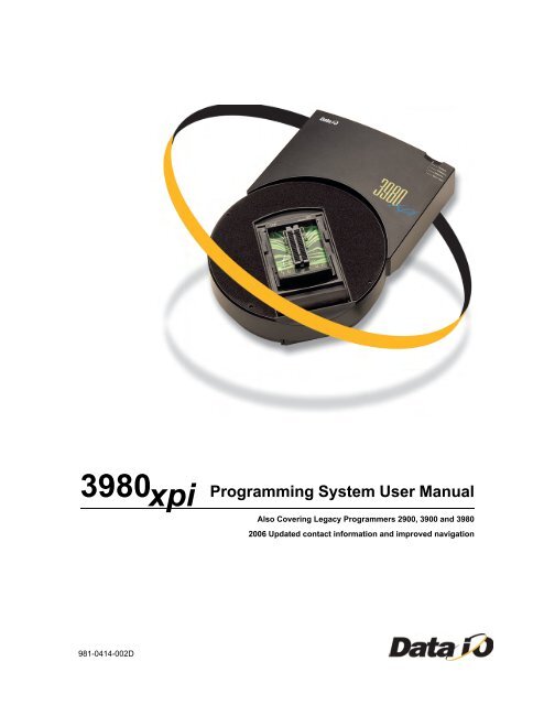
3980xpi Users Manual - Data I/O Corporation
3980xpi Users Manual - Data I/O Corporation
3980xpi Users Manual - Data I/O Corporation

You also want an ePaper? Increase the reach of your titles
YUMPU automatically turns print PDFs into web optimized ePapers that Google loves.
3980 Programming System User <strong>Manual</strong><br />
981-0414-002D<br />
xpi<br />
Also Covering Legacy Programmers 2900, 3900 and 3980<br />
2006 Updated contact information and improved navigation
981-0414-002D<br />
<strong>Data</strong> I/O has made every attempt to ensure that the information in this document is<br />
accurate and complete. <strong>Data</strong> I/O assumes no liability for errors or for any incidental,<br />
consequential, indirect, or special damages, including, without limitation, loss of use, loss<br />
or alteration of data, delays, or lost profits or savings, arising from the use of this document<br />
or the product which it accompanies.<br />
No part of this document may be reproduced or transmitted in any form or by any means,<br />
electronic or mechanical, for any purpose without written permission from <strong>Data</strong> I/O.<br />
<strong>Data</strong> I/O <strong>Corporation</strong><br />
6464 185th Avenue N.E., Suite 101<br />
Redmond, Washington USA 98052<br />
(425) 881-6444<br />
http://www.dataio.com<br />
Acknowledgments:<br />
<strong>Data</strong> I/O is a registered trademark and AutoBaud, Keep Current, MatchBook, SmartPort,<br />
and HiTerm Terminal Emulator are trademarks of <strong>Data</strong> I/O <strong>Corporation</strong>.<br />
<strong>Data</strong> I/O <strong>Corporation</strong> acknowledges the trademarks of other organizations for their<br />
respective products or services mentioned in this document.<br />
Portions of the 2900, 3900, 3980 and <strong>3980xpi</strong> Programming Systems are protected under<br />
U.S. Patent numbers 4,837,653; 4,840,576; 5,176,525; and 5,289,118. Other U.S. and<br />
Foreign Patents Pending.<br />
© 2001, 2006 <strong>Data</strong> I/O <strong>Corporation</strong><br />
All rights reserved
Contents<br />
Contents<br />
Preface<br />
Safety Summary<br />
Figures . . . . . . . . . . . . . . . . . . . . . . . . . . . . . . . . . . . . . . . . . . . . . . . viii<br />
<strong>Data</strong> I/O Customer Support . . . . . . . . . . . . . . . . . . . . . . . . . . . . . . . . . xi<br />
Contacting <strong>Data</strong> I/O . . . . . . . . . . . . . . . . . . . . . . . . . . . . . . . . . . . . . . . xii<br />
Warranty Information . . . . . . . . . . . . . . . . . . . . . . . . . . . . . . . . . . . . . . xii<br />
Keep Current Subscription Service . . . . . . . . . . . . . . . . . . . . . . . . . . . . xiii<br />
Repair Service . . . . . . . . . . . . . . . . . . . . . . . . . . . . . . . . . . . . . . . . . . xiii<br />
End User Registration and Address Change . . . . . . . . . . . . . . . . . . . . . . xiii<br />
1. Introduction<br />
Product Descriptions . . . . . . . . . . . . . . . . . . . . . . . . . . . . . . . . . . . . . . 1-1<br />
Configurations . . . . . . . . . . . . . . . . . . . . . . . . . . . . . . . . . . . . . . . . . . 1-1<br />
Device Support. . . . . . . . . . . . . . . . . . . . . . . . . . . . . . . . . . . . . . . . . . 1-2<br />
Contents of Package . . . . . . . . . . . . . . . . . . . . . . . . . . . . . . . . . . . . . . 1-2<br />
External Features . . . . . . . . . . . . . . . . . . . . . . . . . . . . . . . . . . . . . . . . 1-3<br />
Disks. . . . . . . . . . . . . . . . . . . . . . . . . . . . . . . . . . . . . . . . . . . . . . . . . 1-4<br />
Programmer Disks . . . . . . . . . . . . . . . . . . . . . . . . . . . . . . . . . . . . . 1-4<br />
PC Disk. . . . . . . . . . . . . . . . . . . . . . . . . . . . . . . . . . . . . . . . . . . . . 1-5<br />
Specifications . . . . . . . . . . . . . . . . . . . . . . . . . . . . . . . . . . . . . . . . . . . 1-6<br />
Physical and Environmental . . . . . . . . . . . . . . . . . . . . . . . . . . . . . . 1-7<br />
Safety . . . . . . . . . . . . . . . . . . . . . . . . . . . . . . . . . . . . . . . . . . . . . 1-7<br />
Certificate of RFI/EMI Compliance . . . . . . . . . . . . . . . . . . . . . . . . . . 1-7<br />
Performance Verification. . . . . . . . . . . . . . . . . . . . . . . . . . . . . . . . . 1-7<br />
Options . . . . . . . . . . . . . . . . . . . . . . . . . . . . . . . . . . . . . . . . . . . . . . . 1-8<br />
2. Setting Up<br />
1. Choose Your Configuration and Connect the Equipment . . . . . . . . . . . . 2-1<br />
Connecting to a PC . . . . . . . . . . . . . . . . . . . . . . . . . . . . . . . . . . . . 2-2<br />
Connecting to a Host . . . . . . . . . . . . . . . . . . . . . . . . . . . . . . . . . . . 2-5<br />
More About Cables . . . . . . . . . . . . . . . . . . . . . . . . . . . . . . . . . . . . . 2-9<br />
2. Insert Boot Disk in Programmer . . . . . . . . . . . . . . . . . . . . . . . . . . . 2-11<br />
3. Install the Base. . . . . . . . . . . . . . . . . . . . . . . . . . . . . . . . . . . . . . . 2-12<br />
4. Turn On the Programmer . . . . . . . . . . . . . . . . . . . . . . . . . . . . . . . 2-15<br />
5. Check Self-test Results . . . . . . . . . . . . . . . . . . . . . . . . . . . . . . . . . 2-16<br />
6. Start-up Screen . . . . . . . . . . . . . . . . . . . . . . . . . . . . . . . . . . . . . . 2-18<br />
7. Set Up High Speed Download (optional) . . . . . . . . . . . . . . . . . . . . . 2-20<br />
Setting Up High Speed Download with TaskLink for Windows/DOS. . . 2-20<br />
Setting Up High Speed Serial Download with HiTerm . . . . . . . . . . . . 2-20<br />
8. Install Devices . . . . . . . . . . . . . . . . . . . . . . . . . . . . . . . . . . . . . . . 2-22<br />
Inserting a DIP Device into a DIP Base . . . . . . . . . . . . . . . . . . . . . . 2-22<br />
Installing a MatchBook into a Base . . . . . . . . . . . . . . . . . . . . . . . . 2-23<br />
Inserting a PLCC or LCC Device into a MatchBook . . . . . . . . . . . . . . 2-24<br />
<strong>3980xpi</strong>/3980/3900/2900 User <strong>Manual</strong> iii
Contents<br />
Inserting an SOIC Device into a MatchBook . . . . . . . . . . . . . . . . . . 2-25<br />
Inserting a PGA Device into a PGA Base . . . . . . . . . . . . . . . . . . . . . 2-26<br />
Installing a PPI Adapter into the PPI Base . . . . . . . . . . . . . . . . . . . 2-27<br />
High Profile PPI Adapters . . . . . . . . . . . . . . . . . . . . . . . . . . . . . . . 2-28<br />
Inserting Devices in a PPI Adapter . . . . . . . . . . . . . . . . . . . . . . . . . 2-29<br />
9. Preventive Maintenance . . . . . . . . . . . . . . . . . . . . . . . . . . . . . . . . 2-32<br />
Cleaning the Fan . . . . . . . . . . . . . . . . . . . . . . . . . . . . . . . . . . . . . 2-32<br />
Conductive Pad . . . . . . . . . . . . . . . . . . . . . . . . . . . . . . . . . . . . . . 2-32<br />
SPA Block and Base . . . . . . . . . . . . . . . . . . . . . . . . . . . . . . . . . . . 2-33<br />
10. What To Do Next Time. . . . . . . . . . . . . . . . . . . . . . . . . . . . . . . . . 2-35<br />
11. Using the Mass Storage Module (MSM) . . . . . . . . . . . . . . . . . . . . . 2-36<br />
3. Getting Started<br />
Outline of the Programming Operation . . . . . . . . . . . . . . . . . . . . . . . . . 3-1<br />
Session 1: Programming a Device Using TaskLink. . . . . . . . . . . . . . . . . . 3-2<br />
For TaskLink for Windows . . . . . . . . . . . . . . . . . . . . . . . . . . . . . . . . 3-2<br />
Session 2: Navigating Through the Programmer Menus . . . . . . . . . . . . . 3-10<br />
Programmer Main Menu . . . . . . . . . . . . . . . . . . . . . . . . . . . . . . . . 3-10<br />
Moving Around . . . . . . . . . . . . . . . . . . . . . . . . . . . . . . . . . . . . . . 3-11<br />
Selecting a Menu Item . . . . . . . . . . . . . . . . . . . . . . . . . . . . . . . . . 3-11<br />
Using Key Functions . . . . . . . . . . . . . . . . . . . . . . . . . . . . . . . . . . . 3-12<br />
Selecting Online Help . . . . . . . . . . . . . . . . . . . . . . . . . . . . . . . . . . 3-13<br />
Review . . . . . . . . . . . . . . . . . . . . . . . . . . . . . . . . . . . . . . . . . . . . 3-14<br />
Session 3: Selecting a Device. . . . . . . . . . . . . . . . . . . . . . . . . . . . . . . 3-15<br />
Select a Manufacturer . . . . . . . . . . . . . . . . . . . . . . . . . . . . . . . . . 3-15<br />
Select a Device Part Number . . . . . . . . . . . . . . . . . . . . . . . . . . . . . 3-16<br />
Accessing Device-specific Online Information . . . . . . . . . . . . . . . . . 3-16<br />
Review . . . . . . . . . . . . . . . . . . . . . . . . . . . . . . . . . . . . . . . . . . . . 3-16<br />
Session 4: Selecting a Keep Current Algorithm. . . . . . . . . . . . . . . . . . . 3-17<br />
Insert the Keep Current Algorithm Disk . . . . . . . . . . . . . . . . . . . . . 3-17<br />
Select the Keep Current Option . . . . . . . . . . . . . . . . . . . . . . . . . . . 3-17<br />
Select the Keep Current Algorithm . . . . . . . . . . . . . . . . . . . . . . . . . 3-18<br />
Keep Current Algorithms and Software Updates . . . . . . . . . . . . . . . 3-19<br />
Session 5: Loading <strong>Data</strong> from a Device . . . . . . . . . . . . . . . . . . . . . . . . 3-20<br />
Select the Device. . . . . . . . . . . . . . . . . . . . . . . . . . . . . . . . . . . . . 3-20<br />
Insert the Master Device. . . . . . . . . . . . . . . . . . . . . . . . . . . . . . . . 3-20<br />
Set the Parameters . . . . . . . . . . . . . . . . . . . . . . . . . . . . . . . . . . . 3-21<br />
Load the <strong>Data</strong> . . . . . . . . . . . . . . . . . . . . . . . . . . . . . . . . . . . . . . . 3-22<br />
Review . . . . . . . . . . . . . . . . . . . . . . . . . . . . . . . . . . . . . . . . . . . . 3-22<br />
Session 6: Loading <strong>Data</strong> from a Disk. . . . . . . . . . . . . . . . . . . . . . . . . . 3-23<br />
Review . . . . . . . . . . . . . . . . . . . . . . . . . . . . . . . . . . . . . . . . . . . . 3-24<br />
Session 7: Selecting a Translation Format . . . . . . . . . . . . . . . . . . . . . . 3-25<br />
Review . . . . . . . . . . . . . . . . . . . . . . . . . . . . . . . . . . . . . . . . . . . . 3-25<br />
Session 8: Loading <strong>Data</strong> from a PC Using HiTerm . . . . . . . . . . . . . . . . . 3-26<br />
Prepare the Programmer . . . . . . . . . . . . . . . . . . . . . . . . . . . . . . . 3-26<br />
Download the File . . . . . . . . . . . . . . . . . . . . . . . . . . . . . . . . . . . . 3-27<br />
Review . . . . . . . . . . . . . . . . . . . . . . . . . . . . . . . . . . . . . . . . . . . . 3-27<br />
Session 9: Loading <strong>Data</strong> from a Host . . . . . . . . . . . . . . . . . . . . . . . . . 3-28<br />
Prepare the Programmer . . . . . . . . . . . . . . . . . . . . . . . . . . . . . . . 3-29<br />
Download the File . . . . . . . . . . . . . . . . . . . . . . . . . . . . . . . . . . . . 3-30<br />
Review . . . . . . . . . . . . . . . . . . . . . . . . . . . . . . . . . . . . . . . . . . . . 3-30<br />
Session 10: Editing <strong>Data</strong> . . . . . . . . . . . . . . . . . . . . . . . . . . . . . . . . . . 3-31<br />
Review . . . . . . . . . . . . . . . . . . . . . . . . . . . . . . . . . . . . . . . . . . . . 3-32<br />
iv <strong>3980xpi</strong>/3980/3900/2900 User <strong>Manual</strong>
Contents<br />
Session 11: Programming a Memory Device. . . . . . . . . . . . . . . . . . . . . 3-33<br />
Load the <strong>Data</strong> File . . . . . . . . . . . . . . . . . . . . . . . . . . . . . . . . . . . . 3-33<br />
Set the Parameters . . . . . . . . . . . . . . . . . . . . . . . . . . . . . . . . . . . 3-33<br />
Program the Device . . . . . . . . . . . . . . . . . . . . . . . . . . . . . . . . . . . 3-34<br />
Review . . . . . . . . . . . . . . . . . . . . . . . . . . . . . . . . . . . . . . . . . . . . 3-34<br />
Session 12: Verifying a Device . . . . . . . . . . . . . . . . . . . . . . . . . . . . . . 3-35<br />
Set the Parameters . . . . . . . . . . . . . . . . . . . . . . . . . . . . . . . . . . . 3-35<br />
Verify the Device . . . . . . . . . . . . . . . . . . . . . . . . . . . . . . . . . . . . . 3-36<br />
Review . . . . . . . . . . . . . . . . . . . . . . . . . . . . . . . . . . . . . . . . . . . . 3-36<br />
4. Commands<br />
Overwriting User RAM . . . . . . . . . . . . . . . . . . . . . . . . . . . . . . . . . . . . . 4-1<br />
Factory Default Settings . . . . . . . . . . . . . . . . . . . . . . . . . . . . . . . . . . . 4-3<br />
Select Device (Terminal Mode) . . . . . . . . . . . . . . . . . . . . . . . . . . . . . . . 4-5<br />
Before You Select a Device . . . . . . . . . . . . . . . . . . . . . . . . . . . . . 4-5<br />
Select a Device . . . . . . . . . . . . . . . . . . . . . . . . . . . . . . . . . . . . . . . 4-5<br />
After You Select a Device . . . . . . . . . . . . . . . . . . . . . . . . . . . . . . . . 4-7<br />
Quick Copy . . . . . . . . . . . . . . . . . . . . . . . . . . . . . . . . . . . . . . . . . . . . 4-7<br />
Load Device . . . . . . . . . . . . . . . . . . . . . . . . . . . . . . . . . . . . . . . . . . . . 4-8<br />
Load Logic Device . . . . . . . . . . . . . . . . . . . . . . . . . . . . . . . . . . . . . 4-8<br />
Load Memory Device . . . . . . . . . . . . . . . . . . . . . . . . . . . . . . . . . . . 4-8<br />
Program Device . . . . . . . . . . . . . . . . . . . . . . . . . . . . . . . . . . . . . . . . 4-10<br />
Program Logic Device . . . . . . . . . . . . . . . . . . . . . . . . . . . . . . . . . 4-10<br />
Program Memory Device . . . . . . . . . . . . . . . . . . . . . . . . . . . . . . . 4-12<br />
Enhanced Security Fuse Capability. . . . . . . . . . . . . . . . . . . . . . . . . 4-14<br />
Verify Device . . . . . . . . . . . . . . . . . . . . . . . . . . . . . . . . . . . . . . . . . . 4-15<br />
Verify Logic Device . . . . . . . . . . . . . . . . . . . . . . . . . . . . . . . . . . . 4-15<br />
Verify Memory Device . . . . . . . . . . . . . . . . . . . . . . . . . . . . . . . . . 4-16<br />
More Commands. . . . . . . . . . . . . . . . . . . . . . . . . . . . . . . . . . . . . . . . 4-18<br />
Configure System . . . . . . . . . . . . . . . . . . . . . . . . . . . . . . . . . . . . 4-19<br />
Device Checks . . . . . . . . . . . . . . . . . . . . . . . . . . . . . . . . . . . . . . . 4-39<br />
Edit <strong>Data</strong> . . . . . . . . . . . . . . . . . . . . . . . . . . . . . . . . . . . . . . . . . . 4-45<br />
File Operations . . . . . . . . . . . . . . . . . . . . . . . . . . . . . . . . . . . . . . 4-53<br />
Job File. . . . . . . . . . . . . . . . . . . . . . . . . . . . . . . . . . . . . . . . . . . . 4-58<br />
Remote Control . . . . . . . . . . . . . . . . . . . . . . . . . . . . . . . . . . . . . . 4-59<br />
Self-test . . . . . . . . . . . . . . . . . . . . . . . . . . . . . . . . . . . . . . . . . . . 4-60<br />
Transfer <strong>Data</strong> . . . . . . . . . . . . . . . . . . . . . . . . . . . . . . . . . . . . . . . 4-61<br />
Yield Tally . . . . . . . . . . . . . . . . . . . . . . . . . . . . . . . . . . . . . . . . . . 4-69<br />
5. Translation Formats<br />
Introduction . . . . . . . . . . . . . . . . . . . . . . . . . . . . . . . . . . . . . . . . . . . . 5-1<br />
Instrument Control Codes . . . . . . . . . . . . . . . . . . . . . . . . . . . . . . . . . . 5-2<br />
General Notes . . . . . . . . . . . . . . . . . . . . . . . . . . . . . . . . . . . . . . . . . . 5-2<br />
ASCII Binary Format, Codes 01, 02, and 03 (or 05, 06, and 07). . . . . . . . 5-3<br />
Texas Instruments SDSMAC Format (320), Code 04 . . . . . . . . . . . . . . . . 5-4<br />
5-Level BNPF Format, Codes 08 or 09 . . . . . . . . . . . . . . . . . . . . . . . . . . 5-5<br />
Formatted Binary Format, Code 10 . . . . . . . . . . . . . . . . . . . . . . . . . . . . 5-6<br />
DEC Binary Format, Code 11 . . . . . . . . . . . . . . . . . . . . . . . . . . . . . . . . 5-7<br />
Spectrum Format, Codes 12 or 13 . . . . . . . . . . . . . . . . . . . . . . . . . . . . 5-8<br />
POF (Programmer Object File) Format, Code 14 . . . . . . . . . . . . . . . . . . . 5-9<br />
Absolute Binary Format, Code 16 . . . . . . . . . . . . . . . . . . . . . . . . . . . . 5-11<br />
LOF Format, Code 17 . . . . . . . . . . . . . . . . . . . . . . . . . . . . . . . . . . . . 5-12<br />
LOF Field Syntax . . . . . . . . . . . . . . . . . . . . . . . . . . . . . . . . . . . . . 5-12<br />
<strong>3980xpi</strong>/3980/3900/2900 User <strong>Manual</strong> v
Contents<br />
6. Messages<br />
ASCII Octal and Hex Formats, Codes 30-37 and 50-58 . . . . . . . . . . . . . 5-14<br />
RCA Cosmac Format, Code 70 . . . . . . . . . . . . . . . . . . . . . . . . . . . . . . 5-16<br />
Fairchild Fairbug, Code 80 . . . . . . . . . . . . . . . . . . . . . . . . . . . . . . . . . 5-17<br />
MOS Technology Format, Code 81 . . . . . . . . . . . . . . . . . . . . . . . . . . . 5-18<br />
Motorola EXORciser Format, Code 82 . . . . . . . . . . . . . . . . . . . . . . . . . 5-19<br />
Intel Intellec 8/MDS Format, Code 83 . . . . . . . . . . . . . . . . . . . . . . . . . 5-20<br />
Signetics Absolute Object Format, Code 85 . . . . . . . . . . . . . . . . . . . . . 5-20<br />
Tektronix Hexadecimal Format, Code 86 . . . . . . . . . . . . . . . . . . . . . . . 5-21<br />
Motorola EXORmacs Format, Code 87 . . . . . . . . . . . . . . . . . . . . . . . . . 5-22<br />
Intel MCS-86 Hexadecimal Object, Code 88 . . . . . . . . . . . . . . . . . . . . . 5-23<br />
Hewlett-Packard 64000 Absolute Format, Code 89 . . . . . . . . . . . . . . . . 5-25<br />
Texas Instruments SDSMAC Format, Code 90 . . . . . . . . . . . . . . . . . . . 5-26<br />
JEDEC Format, Codes 91 and 92. . . . . . . . . . . . . . . . . . . . . . . . . . . . . 5-27<br />
BNF Rules and Standard Definitions . . . . . . . . . . . . . . . . . . . . . . . . 5-28<br />
JEDEC Full Format, Code 91 . . . . . . . . . . . . . . . . . . . . . . . . . . . . . . . . 5-30<br />
JEDEC Field Syntax . . . . . . . . . . . . . . . . . . . . . . . . . . . . . . . . . . . 5-31<br />
Field Identifiers . . . . . . . . . . . . . . . . . . . . . . . . . . . . . . . . . . . . . . 5-31<br />
JEDEC U and E Fields . . . . . . . . . . . . . . . . . . . . . . . . . . . . . . . . . . 5-34<br />
JEDEC Kernel Mode, Code 92 . . . . . . . . . . . . . . . . . . . . . . . . . . . . . . . 5-37<br />
Extended Tektronix Hexadecimal Format, Code 94 . . . . . . . . . . . . . . . . 5-37<br />
Motorola 32-Bit Format, Code 95 . . . . . . . . . . . . . . . . . . . . . . . . . . . . 5-39<br />
Hewlett-Packard UNIX Format, Code 96 . . . . . . . . . . . . . . . . . . . . . . . 5-40<br />
Intel OMF386 Format, Code 97. . . . . . . . . . . . . . . . . . . . . . . . . . . . . . 5-41<br />
Intel OMF286 Format, Code 98. . . . . . . . . . . . . . . . . . . . . . . . . . . . . . 5-42<br />
Intel Hex-32, Code 99 . . . . . . . . . . . . . . . . . . . . . . . . . . . . . . . . . . . . 5-44<br />
Highest I/O Addresses. . . . . . . . . . . . . . . . . . . . . . . . . . . . . . . . . . . . 5-46<br />
Message List . . . . . . . . . . . . . . . . . . . . . . . . . . . . . . . . . . . . . . . . . . . 6-1<br />
Device Insertion Error When Using Elastomeric Pad . . . . . . . . . . . . . . . 6-11<br />
Device Over-current Fault . . . . . . . . . . . . . . . . . . . . . . . . . . . . . . . . 6-13<br />
Device Programming Error . . . . . . . . . . . . . . . . . . . . . . . . . . . . . . . . 6-14<br />
Invalid Device ID on Logic Device . . . . . . . . . . . . . . . . . . . . . . . . . . . . 6-15<br />
Electronic ID Verify Error on Memory Device . . . . . . . . . . . . . . . . . . . . 6-16<br />
Illegal Bit Error . . . . . . . . . . . . . . . . . . . . . . . . . . . . . . . . . . . . . . 6-17<br />
I/O Timeout Error . . . . . . . . . . . . . . . . . . . . . . . . . . . . . . . . . . . . . . 6-18<br />
Partial or No Transfer Performed. . . . . . . . . . . . . . . . . . . . . . . . . . . . . 6-19<br />
Incompatible User <strong>Data</strong> File for Device Selected . . . . . . . . . . . . . . . . . . 6-20<br />
QF and QP fields . . . . . . . . . . . . . . . . . . . . . . . . . . . . . . . . . . . . . 6-20<br />
Appendix A: Performance Verification<br />
Reducing Electrostatic Discharge . . . . . . . . . . . . . . . . . . . . . . . . . . . . . A-1<br />
Accessing Test Points . . . . . . . . . . . . . . . . . . . . . . . . . . . . . . . . . . . . . A-2<br />
Checking the Master Clock . . . . . . . . . . . . . . . . . . . . . . . . . . . . . . . . . . A-4<br />
Checking the Reference Voltages . . . . . . . . . . . . . . . . . . . . . . . . . . . . . A-4<br />
Reassembling the Programmer . . . . . . . . . . . . . . . . . . . . . . . . . . . . . . . A-5<br />
Appendix B: Computer Remote Control<br />
System Setup. . . . . . . . . . . . . . . . . . . . . . . . . . . . . . . . . . . . . . . . . . . B-1<br />
Entering CRC Mode . . . . . . . . . . . . . . . . . . . . . . . . . . . . . . . . . . . . B-2<br />
Exiting CRC Mode . . . . . . . . . . . . . . . . . . . . . . . . . . . . . . . . . . . . . B-3<br />
Suspending CRC Mode . . . . . . . . . . . . . . . . . . . . . . . . . . . . . . . . . . B-3<br />
Halting CRC Operations . . . . . . . . . . . . . . . . . . . . . . . . . . . . . . . . . B-4<br />
vi <strong>3980xpi</strong>/3980/3900/2900 User <strong>Manual</strong>
Contents<br />
CRC Default Settings. . . . . . . . . . . . . . . . . . . . . . . . . . . . . . . . . . . . . . B-4<br />
CRC Commands . . . . . . . . . . . . . . . . . . . . . . . . . . . . . . . . . . . . . . . . . B-5<br />
Appendix C: Keep Current Subscription<br />
Computer Requirements . . . . . . . . . . . . . . . . . . . . . . . . . . . . . . . . . . . C-1<br />
Procedure Overview . . . . . . . . . . . . . . . . . . . . . . . . . . . . . . . . . . . . . . C-2<br />
1. Gather Information . . . . . . . . . . . . . . . . . . . . . . . . . . . . . . . . . . . . . C-2<br />
2. Connect to Keep Current . . . . . . . . . . . . . . . . . . . . . . . . . . . . . . . . . C-3<br />
3. Find Device Algorithm . . . . . . . . . . . . . . . . . . . . . . . . . . . . . . . . . . . C-3<br />
4. Download Algorithm . . . . . . . . . . . . . . . . . . . . . . . . . . . . . . . . . . . . C-4<br />
5. Use Algorithm. . . . . . . . . . . . . . . . . . . . . . . . . . . . . . . . . . . . . . . . . C-4<br />
Appendix D: Glossary<br />
Index<br />
User Notes<br />
Application Notes<br />
Utilities<br />
<strong>3980xpi</strong>/3980/3900/2900 User <strong>Manual</strong> vii
Figures<br />
Figure Page<br />
1-1. Contents of the Programming System . . . . . . . . . . . . . . . . . . . . . . 1-2<br />
1-2. Front Panel Features . . . . . . . . . . . . . . . . . . . . . . . . . . . . . . . . . . 1-3<br />
1-3. Back Panel Features . . . . . . . . . . . . . . . . . . . . . . . . . . . . . . . . . . . 1-4<br />
2-1. Pin Designations for RS-232C Serial Port Connection . . . . . . . . . . . . 2-9<br />
2-2. Write-enabled Disk. . . . . . . . . . . . . . . . . . . . . . . . . . . . . . . . . . . 2-11<br />
2-3. Inserting the Boot Disk (2900/3900) . . . . . . . . . . . . . . . . . . . . . . 2-11<br />
2-4. Base Opening . . . . . . . . . . . . . . . . . . . . . . . . . . . . . . . . . . . . . . 2-12<br />
2-5. Aligning the Base . . . . . . . . . . . . . . . . . . . . . . . . . . . . . . . . . . . . 2-13<br />
2-6. Removing a Base . . . . . . . . . . . . . . . . . . . . . . . . . . . . . . . . . . . . 2-14<br />
2-7. Connection Established Message . . . . . . . . . . . . . . . . . . . . . . . . . 2-18<br />
2-8. Typical Start-up Screen For HiTerm <strong>Users</strong> . . . . . . . . . . . . . . . . . . . 2-19<br />
2-9. Inserting a DIP Device into the DIP Base . . . . . . . . . . . . . . . . . . . 2-22<br />
2-10. Inserting a MatchBook into the Base. . . . . . . . . . . . . . . . . . . . . . 2-23<br />
2-11. Closing the MatchBook . . . . . . . . . . . . . . . . . . . . . . . . . . . . . . . 2-23<br />
2-12. Inserting a Device into the PLCC or LCC Base . . . . . . . . . . . . . . . 2-24<br />
2-13. Inserting an SOIC Device . . . . . . . . . . . . . . . . . . . . . . . . . . . . . 2-25<br />
2-14. Orienting a PGA Device in the PGA Base . . . . . . . . . . . . . . . . . . . 2-26<br />
2-15. High Profile PPI Adapter . . . . . . . . . . . . . . . . . . . . . . . . . . . . . . 2-28<br />
2-16. Inserting a TSOP Device in a PPI Base . . . . . . . . . . . . . . . . . . . . 2-29<br />
2-17. Inserting a QFP Device in a PPI Adapter . . . . . . . . . . . . . . . . . . . 2-30<br />
2-18. Inserting an SOIC Device in a PPI Adapter . . . . . . . . . . . . . . . . . 2-31<br />
2-19. Inserting an SDIP device in a PPI Adapter . . . . . . . . . . . . . . . . . . 2-31<br />
2-20. Conductive Pad . . . . . . . . . . . . . . . . . . . . . . . . . . . . . . . . . . . . 2-32<br />
2-21. SPA Block and Base . . . . . . . . . . . . . . . . . . . . . . . . . . . . . . . . . 2-34<br />
3-1. Main Menu . . . . . . . . . . . . . . . . . . . . . . . . . . . . . . . . . . . . . . . . 3-10<br />
3-2. More Commands Menu Screen. . . . . . . . . . . . . . . . . . . . . . . . . . . 3-11<br />
3-3. Self-test Screen . . . . . . . . . . . . . . . . . . . . . . . . . . . . . . . . . . . . . 3-12<br />
3-4. Areas of the Help Screen . . . . . . . . . . . . . . . . . . . . . . . . . . . . . . 3-13<br />
3-5. Device Manufacturer Selection Screen . . . . . . . . . . . . . . . . . . . . . 3-15<br />
3-6. Part Number Selection Screen . . . . . . . . . . . . . . . . . . . . . . . . . . . 3-16<br />
3-7. Device Manufacturer Selection Screen . . . . . . . . . . . . . . . . . . . . . 3-17<br />
3-8. Keep Current Part Number Selection Screen . . . . . . . . . . . . . . . . . 3-18<br />
3-9. Locking and Unlocking a Device . . . . . . . . . . . . . . . . . . . . . . . . . . 3-21<br />
3-10. Load Memory Device Screen (Non-default Parameters). . . . . . . . . 3-21<br />
3-11. Load Memory Screen (All Parameters) . . . . . . . . . . . . . . . . . . . . 3-22<br />
3-12. File Menu . . . . . . . . . . . . . . . . . . . . . . . . . . . . . . . . . . . . . . . . 3-23<br />
3-13. Load File Dialog Screen. . . . . . . . . . . . . . . . . . . . . . . . . . . . . . . 3-24<br />
3-14. Translation Format Selection Screen. . . . . . . . . . . . . . . . . . . . . . 3-25<br />
3-15. Download <strong>Data</strong> from Host Screen. . . . . . . . . . . . . . . . . . . . . . . . 3-26<br />
3-16. Download <strong>Data</strong> from Host Screen. . . . . . . . . . . . . . . . . . . . . . . . 3-29<br />
3-17. Edit Programmer Memory Screen . . . . . . . . . . . . . . . . . . . . . . . . 3-31<br />
3-18. Edit Screen . . . . . . . . . . . . . . . . . . . . . . . . . . . . . . . . . . . . . . . 3-31<br />
3-19. Program Memory Device Screen (Non-default Parameters) . . . . . . 3-33<br />
3-20. Program Memory Device Screen (All Parameters). . . . . . . . . . . . . 3-34<br />
3-21. Verify Memory Device Screen (Non-default Parameters) . . . . . . . . 3-35<br />
3-22. Verify Memory Device Screen (All Parameters) . . . . . . . . . . . . . . 3-36<br />
4-1. Command Tree (page numbers are in italics) . . . . . . . . . . . . . . . . . 4-2<br />
5-1. ASCII Binary Format (example) . . . . . . . . . . . . . . . . . . . . . . . . . . . 5-3<br />
5-2. TI SDSMAC Format (example) . . . . . . . . . . . . . . . . . . . . . . . . . . . . 5-4<br />
5-3. Formatted Binary Format (example). . . . . . . . . . . . . . . . . . . . . . . . 5-6<br />
viii <strong>3980xpi</strong>/3980/3900/2900 User <strong>Manual</strong>
Figure Page<br />
5-4. Formatted Binary Format (example). . . . . . . . . . . . . . . . . . . . . . . . 5-7<br />
5-5. Spectrum Format (example) . . . . . . . . . . . . . . . . . . . . . . . . . . . . . 5-8<br />
5-6. ASCII Octal and Hex Formats (example). . . . . . . . . . . . . . . . . . . . 5-14<br />
5-7. RCA Cosmac Format (example) . . . . . . . . . . . . . . . . . . . . . . . . . . 5-16<br />
5-8. Fairchild Fairbug (example). . . . . . . . . . . . . . . . . . . . . . . . . . . . . 5-17<br />
5-9. MOS Technology Format (example) . . . . . . . . . . . . . . . . . . . . . . . 5-18<br />
5-10. Motorola EXORciser Format (example) . . . . . . . . . . . . . . . . . . . . 5-19<br />
5-11. Intel Intellec 8/MDS Format (example) . . . . . . . . . . . . . . . . . . . . 5-20<br />
5-12. An Example of Signetics Absolute Object Format . . . . . . . . . . . . . 5-20<br />
5-13. Tektronix Hex Format (example) . . . . . . . . . . . . . . . . . . . . . . . . 5-21<br />
5-14. Motorola EXORmacs Format (example) . . . . . . . . . . . . . . . . . . . . 5-22<br />
5-15. Intel MCS-86 Hex Object (example) . . . . . . . . . . . . . . . . . . . . . . 5-23<br />
5-16. HP 64000 Absolute Format (example). . . . . . . . . . . . . . . . . . . . . 5-25<br />
5-17. TI SDSMAC Format (example) . . . . . . . . . . . . . . . . . . . . . . . . . . 5-26<br />
5-18. JEDEC Full Format (example) . . . . . . . . . . . . . . . . . . . . . . . . . . 5-30<br />
5-19. JEDEC Kernel Mode Format (example) . . . . . . . . . . . . . . . . . . . . 5-37<br />
5-20. An Example of Tektronix Extended Format . . . . . . . . . . . . . . . . . 5-37<br />
5-21. Motorola S3 Format (example) . . . . . . . . . . . . . . . . . . . . . . . . . 5-39<br />
5-22. Hewlett-Packard 64000 Unix Format. . . . . . . . . . . . . . . . . . . . . . 5-41<br />
5-23. Intel OMF286 Format (example) . . . . . . . . . . . . . . . . . . . . . . . . 5-42<br />
5-24. Close-up of Intel OMF286 Format. . . . . . . . . . . . . . . . . . . . . . . . 5-43<br />
5-25. Intel Hex-32 Format (example) . . . . . . . . . . . . . . . . . . . . . . . . . 5-44<br />
A-1. Removing the Rear Panel Screws . . . . . . . . . . . . . . . . . . . . . . . . . . A-2<br />
A-2. Removing the Top Cover Screws . . . . . . . . . . . . . . . . . . . . . . . . . . A-3<br />
A-3. Waveform Board . . . . . . . . . . . . . . . . . . . . . . . . . . . . . . . . . . . . . A-3<br />
A-4. Test Points on the Connector Block . . . . . . . . . . . . . . . . . . . . . . . . A-4<br />
<strong>3980xpi</strong>/3980/3900/2900 User <strong>Manual</strong> ix
Preface<br />
The Preface describes how to contact <strong>Data</strong> I/O for technical assistance,<br />
repair and warranty services, and Keep Current subscription service.<br />
It also describes how to reach <strong>Data</strong> I/O on the World Wide Web.<br />
<strong>Data</strong> I/O Customer Support<br />
United<br />
States<br />
For technical assistance, repair,<br />
warranty service, or Keep Current<br />
subscription service, contact:<br />
China For technical assistance, repair,<br />
warranty service, or Keep Current<br />
subscription service, contact:<br />
Hong Kong For technical assistance, repair,<br />
warranty service, or Keep Current<br />
subscription service, contact:<br />
Germany For technical assistance, repair,<br />
warranty service, or Keep Current<br />
subscription service, contact:<br />
Other<br />
Countries<br />
For technical assistance, repair,<br />
warranty service, or Keep Current<br />
subscription service, contact:<br />
<strong>Data</strong> I/O <strong>Corporation</strong><br />
6464 185th Avenue NE, Suite 101<br />
Redmond, WA USA 98052<br />
Telephone: 425-881-6444<br />
1-800-3-DATAIO (1-800-332-8246)<br />
Fax: 425-867-6972<br />
E-mail: support@dataio.com<br />
<strong>Data</strong> I/O China<br />
Suite A, 25F Majesty Building<br />
138 Pudong Avenue<br />
Shanghai, China PRC 200120<br />
Telephone: 21-5882-7686<br />
Fax: 21-5882-5053<br />
<strong>Data</strong> I/O Hong Kong<br />
Unit B, 12/F, Aubin House<br />
171-172 Gloucester Road<br />
Wanchai, Hong Kong<br />
Telephone: 852-2558-1533<br />
Fax: 852-2558-1035<br />
<strong>Data</strong> I/O GmbH<br />
Lochhamer Schlag 5<br />
82166 Gräfelfing<br />
Telephone: 89-85858-66<br />
Fax: 89-85858-10<br />
E-mail: servicegmbh@data-io.de<br />
Your local <strong>Data</strong> I/O representative.<br />
To find your local representative, go to<br />
www.dataio.com/contact/repsearch.asp<br />
<strong>3980xpi</strong>/3980/3900/2900 User <strong>Manual</strong> xi
Preface<br />
Contacting <strong>Data</strong> I/O<br />
Telephone<br />
Fax<br />
E-mail<br />
You can contact <strong>Data</strong> I/O for technical assistance by calling, sending a fax<br />
or by electronic mail (e-mail). To help us give you quick and accurate<br />
assistance, please provide the following information:<br />
� Product version number<br />
� Product serial number (if available)<br />
� Detailed description of the problem you are experiencing<br />
� Error messages (if any)<br />
� Device manufacturer and part number (if device-related)<br />
Call the appropriate <strong>Data</strong> I/O Customer Support number listed on the previous<br />
page. When you call, please be at your programmer or computer, have the<br />
product manual nearby, and be ready to provide the information listed above.<br />
Fax the information listed above with your name, telephone number, and<br />
address to the appropriate <strong>Data</strong> I/O Customer Support fax number listed at<br />
the front of the Preface.<br />
To reach <strong>Data</strong> I/O through e-mail, send a message including your name,<br />
telephone number, e-mail address, and the information listed above to:<br />
support@dataio.com<br />
World Wide Web (www.dataio.com)<br />
The <strong>Data</strong> I/O Web site includes links to online information about technical<br />
products, general information about <strong>Data</strong> I/O, a list of sales offices, and<br />
technical user information such as application notes and device lists.<br />
To access the Web, you need an Internet account with Web access and a Web<br />
browser. The address of <strong>Data</strong> I/O's Home Page is http://www.dataio.com.<br />
Warranty Information<br />
<strong>Data</strong> I/O <strong>Corporation</strong> warrants this product against defects in materials and<br />
workmanship at the time of delivery and thereafter for a period of one (1)<br />
year. The foregoing warranty and the manufacturers' warranties, if any, are in<br />
lieu of all other warranties, expressed, implied or arising under law, including,<br />
but not limited to, the implied warranties of merchantability and fitness for a<br />
particular purpose.<br />
<strong>Data</strong> I/O maintains customer service offices throughout the world, each<br />
staffed with factory-trained technicians to provide prompt, quality service.<br />
For warranty service, contact <strong>Data</strong> I/O Customer Support.<br />
xii <strong>3980xpi</strong>/3980/3900/2900 User <strong>Manual</strong>
Keep Current Subscription Service<br />
Repair Service<br />
Preface<br />
To keep your product up-to-date with the latest features and device support,<br />
<strong>Data</strong> I/O offers the Keep Current Subscription Service, a one-year renewable<br />
subscription that incorporates manufacturer-recommended changes to<br />
existing device support to maintain optimum yields, throughput, and longterm<br />
reliability. For more information or to order Keep Current Subscription<br />
Service, contact <strong>Data</strong> I/O Customer Support.<br />
After the warranty period expires, repair services are available at <strong>Data</strong> I/O<br />
Service Centers worldwide. Single instance repairs and fixed price annual<br />
agreements that cover all parts and labor needed to correct normal<br />
malfunctions are also available. The annual agreements include semiannual<br />
performance certification. For more information, or to order a Repair Service<br />
Agreement, contact <strong>Data</strong> I/O Customer Support.<br />
End User Registration and Address Change<br />
If the end user for this product or your address has changed since the<br />
Registration Card was mailed, please notify <strong>Data</strong> I/O Customer Support to<br />
ensure that you receive information about product enhancements. Be sure to<br />
include the product serial number, if available.<br />
<strong>3980xpi</strong>/3980/3900/2900 User <strong>Manual</strong> xiii
Safety Summary<br />
Terms<br />
General safety information for operating personnel is contained<br />
in this summary. In addition, specific WARNINGS and<br />
CAUTIONS appear throughout this manual where they apply<br />
and are not included in this summary.<br />
Antistatic Wrist Strap To avoid electric shock, the antistatic wrist strap must contain a<br />
1 MΩ (minimum) to 10 MΩ (maximum) isolating resistor.<br />
Definitions WARNING statements identify conditions or practices that<br />
could result in personal injury or loss of life. CAUTION<br />
statements identify conditions or practices that could result in<br />
damage to equipment or other property.<br />
Fuse Replacement For continued protection against the possibility of fire, replace<br />
the fuse only with a fuse of the specified voltage, current, and<br />
type ratings.<br />
Grounding the Product The product is grounded through the grounding conductor of the<br />
power cord. To avoid electric shock, plug the power cord into a<br />
properly wired and grounded receptacle only. Grounding this<br />
equipment is essential for its safe operation.<br />
Power Cord Use only the power cord specified for your equipment.<br />
Power Source To avoid damage, operate the equipment only within the<br />
specified line (AC) voltage.<br />
Servicing To reduce the risk of electric shock, perform only the servicing<br />
described in this manual.<br />
<strong>3980xpi</strong>/3980/3900/2900 User <strong>Manual</strong> xv
Safety Summary<br />
Symbols<br />
V<br />
This symbol indicates that the user should consult the<br />
manual for further detail.<br />
This symbol stands for Vac,for example,<br />
120V = 120 Vac.<br />
This symbol denotes a fuse rating for a userreplaceable<br />
fuse.<br />
This symbol denotes a protective ground connection.<br />
This symbol denotes a ground connection for a signal<br />
or for an antistatic wrist strap with impedance of 1 MΩ<br />
(minimum) to 10 MΩ (maximum).<br />
xvi 3980/3900/2900 User <strong>Manual</strong>
1 Introduction<br />
Product Descriptions<br />
Configurations<br />
The <strong>3980xpi</strong> and the Legacy Programming Systems 3980, 3900 and 2900 are<br />
precision tools for programming and verifying virtually all programmable<br />
device technologies and packages.<br />
<strong>3980xpi</strong> Programming System<br />
The <strong>3980xpi</strong> features all the benefits of the 3980 series universal device<br />
programmer with the additional ability to quickly and easily handle devices<br />
that require large data files, as well as other enhancements that make the<br />
programmer easier to use in production or engineering environments.<br />
3980 Programming System<br />
In addition to the features of the 3900, the 3980 has an internal hard disk<br />
drive, the Mass Storage Module, that provides 80 MB of storage space for<br />
system software and device programming algorithms so you do not have to<br />
insert a Boot disk when you power up or switch disks during operation.<br />
3900 Programming System<br />
The 3900 has 88 universal pin drivers capable of supporting devices of all pin<br />
sizes. The optional PLCC base and MatchBooks provide support for over 3000<br />
devices in PLCC packages. The optional PPI Base and adapters support a wide<br />
variety of packages, including SOIC, TSOP, QFP, and µBGA.<br />
2900 Programming System<br />
The 2900 has 44 universal (analog and digital) pin drivers. The standard DIP<br />
base supports DIP packages to 48 pins. The optional PPI Base and adapters<br />
extend support to devices in other package styles.<br />
You can set up your programmer in the following configurations:<br />
� Connected to a PC using TaskLink Software (see page 2-2) or HiTerm<br />
Terminal Emulator (see page 2-4) to control the programmer.<br />
� Connected to a Host, such as a workstation, which you can use to control<br />
the programmer and store data files (see page 2-5).<br />
� Connected to a stand-alone Terminal, such as the DEC VT-100,<br />
Qume VT-101, and Wyse WY-30/40/70 family of terminals (see page 2-6).<br />
<strong>3980xpi</strong>/3980/3900/2900 User <strong>Manual</strong> 1-1
Introduction<br />
Device Support<br />
The most current list of supported devices can be found on our Web site at<br />
http://www.dataio.com.<br />
Contents of Package<br />
Your Programming System package should contain the items shown in<br />
Figure 1-1.<br />
Figure 1-1. Contents of the Programming System<br />
PARALLEL CABLE<br />
TASKLINK CD<br />
PROGRAMMER<br />
USER<br />
MANUAL<br />
<strong>3980xpi</strong><br />
USER MANUAL<br />
UTILITY<br />
DISK<br />
Note: You may also have received additional equipment. Options<br />
are described on page 1-8.<br />
DIP BASE<br />
DISKS<br />
BOOT FILES<br />
ALGORITHM<br />
SYSTEM FILES<br />
POWER CORD 1177-7<br />
1-2 <strong>3980xpi</strong>/3980/3900/2900 User <strong>Manual</strong>
External Features<br />
Front Panel<br />
The front panel features are shown in Figure 1-2.<br />
Figure 1-2. Front Panel Features<br />
LEDs<br />
DISK DRIVE<br />
Power LED—When this lamp is lit, the power is on.<br />
POWER<br />
TERMINAL<br />
REMOTE<br />
SELF TEST<br />
BASE<br />
OPENING<br />
Introduction<br />
Terminal LED—When this lamp is lit, equipment is connected properly to the<br />
Terminal port.<br />
Remote LED—When this lamp is lit, equipment is connected properly to the<br />
Remote port.<br />
Self Test LED—When this lamp is lit, the programmer is performing a selftest.<br />
Base Opening—Insert the Base here.<br />
Disk Drive—Insert the programmer disks (Boot and Algorithm/System disks)<br />
here.<br />
<strong>3980xpi</strong>/3980/3900/2900 User <strong>Manual</strong> 1-3<br />
1019-2
Introduction<br />
Back Panel<br />
The features on the back panel are shown in Figure 1-3.<br />
Figure 1-3. Back Panel Features<br />
Disks<br />
Programmer Disks<br />
POWER<br />
SWITCH<br />
AC RECEPTACLE<br />
REMOTE<br />
PORT<br />
TERMINAL PORT<br />
PARALLEL PORT<br />
Power Switch—Turns power on and off.<br />
GROUND<br />
CONNECTOR<br />
AC Receptacle—Connects the programmer to ac power.<br />
Remote Port—Connects the programmer to equipment such as a PC,<br />
workstation, terminal, or file server.<br />
Parallel Port—Connects the programmer to equipment such as a PC,<br />
workstation, terminal, or file server.<br />
Terminal Port—Connects the programmer to equipment such as a PC,<br />
workstation, terminal, or file server.<br />
Ground Connector—Connector for an antistatic wrist strap.<br />
The Boot Files disk and the Algorithm/System disks are inserted in the<br />
programmer’s disk drive and are configured to work with one specific<br />
programmer. Do not try to use these disks with a different programmer.<br />
After setting up the programmer, make backup copies of the Boot disk and<br />
Algorithm/System disks using disks formatted on the programmer. Use the<br />
copies during daily operation.<br />
Algorithm/System Disks<br />
Algorithm/System disks contain the system software and programming<br />
algorithms for the currently supported devices. Unless your algorithm files are<br />
stored on the <strong>3980xpi</strong>/3980 hard drive or RAM Device Selection is enabled,<br />
one of the Algorithm/System disks must be installed in the programmer disk<br />
drive each time you select a device. You will be prompted for the specific disk<br />
to insert.<br />
1-4 <strong>3980xpi</strong>/3980/3900/2900 User <strong>Manual</strong><br />
1018-3
PC Disk<br />
Boot Files Disk—3900/2900<br />
Introduction<br />
The Boot Files disk contains system software and configuration files used to<br />
boot up the programmer.<br />
The Utility Disk is inserted in the floppy disk drive on your PC.<br />
Utility Disk<br />
The Utility Disk contains HiTerm software for your PC. For more information,<br />
see the manual.doc file on the Utility Disk.<br />
<strong>3980xpi</strong>/3980/3900/2900 User <strong>Manual</strong> 1-5
Introduction<br />
Specifications<br />
Power Requirements<br />
Note: Unless otherwise noted, the specifications apply to all four<br />
programmers.<br />
Electrostatic Discharge (ESD)<br />
Functional<br />
Operating Voltages 90 to 264 VAC<br />
Frequency Range 50 to 60 Hz<br />
Power Consumption 150 VA maximum<br />
Input Current 1.5A maximum<br />
IEC 801-2 (± 8 kV)<br />
RAM 8MB standard<br />
4 MB standard (after 8/97); 8 MB optional—2900<br />
Floppy Disk Format Quad-density, dual-sided 3.5-inch disk with 135 tracks<br />
per inch. 1.44 MB formatted.<br />
Controller Motorola 68000 16-bit microprocessor.<br />
Terminal Support Interfaces with ANSI 3.64 compatible terminals, IBM<br />
PCs, and compatibles using a terminal emulator, and<br />
many popular ASCII terminals.<br />
Communication<br />
Standard RS-232C<br />
SmartPort Automatic DTE/DCE port configuration<br />
<strong>Data</strong> Transfer Rate 110 to 19.2 K baud<br />
(up to 115.2 K baud using HiTerm or TaskLink)<br />
Parallel Port Standard<br />
1-6 <strong>3980xpi</strong>/3980/3900/2900 User <strong>Manual</strong>
Physical and Environmental<br />
Safety<br />
Introduction<br />
Dimension 9.53h x 28.58w x 41.28d cm<br />
3.75h x 11.25w x 16.25d inches<br />
Weight <strong>3980xpi</strong> Operating: 5.12 kg (11.28lb)<br />
Shipping: 7.38 kg (16.28lb)<br />
3980: Operating: 5.10 kg (11.22 lb)<br />
Shipping: 7.36 kg (16.22 lb)<br />
3900: Operating: 5.00 kg (11.0 lb)<br />
Shipping: 7.26 kg (16.0 lb)<br />
2900 Operating: 3.86 kg (8.5 lb)<br />
Shipping: 6.14 kg (13.5 lb)<br />
Temperature Operating:<br />
Storage:<br />
Transportation:<br />
Relative Humidity Operating:<br />
Storage:<br />
Altitude Operating:<br />
Storage:<br />
The <strong>3980xpi</strong> and all legacy programmers are certified by UL and CSA to<br />
comply with the following safety standards:<br />
Certificate of RFI/EMI Compliance<br />
Underwriters Laboratories—UL 60950 Third Edition and/or<br />
EN 60950 Third Edition<br />
<strong>Data</strong> I/O certifies that the <strong>3980xpi</strong> and all legacy programmers comply with<br />
the Radio Frequency Interference (RFI) and Electromagnetic Interference<br />
(EMI) requirements of EN55022 Class A and EN50082-1 as called out in 89/<br />
336/EEC, the EMC Directive for the European Community.<br />
Performance Verification<br />
R<br />
EC conformity mark.<br />
+4°C to +40°C (+40°F to +105°F)<br />
+4°C to +50°C (+40°F to + 122°F)<br />
–40°C to +55°C (–40°F to +130°F)<br />
20 to 80% noncondensing<br />
10 to 90% noncondensing<br />
To 5,000 meters<br />
To 15,000 meters<br />
The programmer verifies internal voltages every time it is powered up and<br />
every time a complete self-test is run. The voltage verification is performed by<br />
software and is compared to a laser-trimmed voltage reference.<br />
<strong>Data</strong> I/O recommends that you cycle power AND run a complete selftest<br />
cycle at least once a day.<br />
To ensure that your programmer continues to meet product performance<br />
specifications, <strong>Data</strong> I/O recommends that you return it to an authorized<br />
<strong>Data</strong> I/O Service Center every twelve months for a complete performance<br />
evaluation.<br />
<strong>3980xpi</strong>/3980/3900/2900 User <strong>Manual</strong> 1-7
Introduction<br />
Options<br />
The following items are designed to complement the 2900, 3900, 3980 and<br />
<strong>3980xpi</strong> Programming Systems. For more information or to order an item,<br />
contact <strong>Data</strong> I/O Inside Sales as listed in the Preface.<br />
Keep Current Subscription Service<br />
TaskLink<br />
MatchBooks<br />
<strong>Data</strong> I/O offers a one-year Keep Current Subscription Service to keep your<br />
programmer up-to-date with the latest features and new device support. This<br />
subscription also incorporates device manufacturer-recommended algorithm<br />
changes to existing device support to maintain optimum yields, throughput,<br />
and long-term device reliability.<br />
As a Keep Current subscriber, you have immediate access to new and updated<br />
programming algorithms using the World Wide Web or Keep Current Express<br />
Bulletin Board Service before the algorithms are available in the update kit.<br />
For more information, see Appendix C.<br />
TaskLink Software, which runs on an IBM-compatible PC, allows you to control<br />
your programmer from a personal computer for streamlined and enhanced<br />
programming operations. TaskLink features automatic programming file<br />
configuration, full-screen editing, error logging, a windowed interface,<br />
extensive online context-sensitive Help, and full mouse support.<br />
The MatchBook Device Carriers and their accompanying Bases allow you to<br />
program surface-mount devices, such as PLCCs, SOICs, and LCCs, without the<br />
mechanical problems and expense of sockets.<br />
PPI Base and Adapters<br />
The PPI Base and adapters support a wide variety of packages, including SOIC,<br />
TSOP, QFP, and µBGA.<br />
Accessory Package<br />
The Accessory Package contains an RS-232C cable and a gender changer.<br />
Elastromer Pad Replacement Kit for PLCC Bases<br />
The package contains a set of five; For PLCC bases.<br />
Elastromer Pad Replacement Kit for SOIC Bases<br />
The package contains a set of five; For SOIC bases.<br />
RAM Upgrade—3980/3900/2900<br />
Installing this upgrade kit increases the RAM in your programmer to 8 MB.<br />
1-8 <strong>3980xpi</strong>/3980/3900/2900 User <strong>Manual</strong>
<strong>3980xpi</strong> Upgrade Kit—3980/3900<br />
Introduction<br />
This kit allow your programmer to be upgraded to the new <strong>3980xpi</strong>. The new<br />
parallel port interface allows for quick data downloads of large devices, with<br />
data throughput up to 600% faster using TaskLink for Windows.®<br />
With its integrated Mass Storage Module, the <strong>3980xpi</strong> provides fast algorithm<br />
selection and high-capacity local data storage. It is fully backwards compatible<br />
with previous software revisions and pre-compiled TaskLink Task or Kits.<br />
This kit includes:<br />
� Tasklink for Windows, system software, and device algorithm CD-ROM<br />
� New back-panel assembly<br />
� 6’ Parallel Interface Cable<br />
� Installation Guide<br />
� <strong>3980xpi</strong> <strong>Users</strong> <strong>Manual</strong><br />
� MSM (required for 3900)<br />
MSM Upgrade—3900<br />
A Mass Storage Module (MSM) upgrade kit, which provides 80 MB of nonvolatile<br />
storage on an internal module, is available for existing 3900<br />
programmers.<br />
The MSM optimizes programmer performance by providing storage for system<br />
software and programming algorithms, which enables fast boot-up and<br />
eliminates the need to access files from the 3-½” disk drive.<br />
The MSM is required to upgrade to the <strong>3980xpi</strong>.<br />
<strong>3980xpi</strong>/3980/3900/2900 User <strong>Manual</strong> 1-9
2 Setting Up<br />
This chapter describes how to set up the programmer and get it working with<br />
your equipment. Before you read this chapter, read Chapter 1, Introduction.<br />
Hardware configuration and software installation are described in the following<br />
steps:<br />
1. Choose Your Configuration and Connect the Equipment<br />
Connect to a PC and Use TaskLink . . . . . . . . . . . . . . . . . . . . . . . .2-2<br />
Connect to a PC and Use HiTerm . . . . . . . . . . . . . . . . . . . . . . . . .2-4<br />
Connect to a Host . . . . . . . . . . . . . . . . . . . . . . . . . . . . . . . . . . .2-5<br />
Connect to a Terminal . . . . . . . . . . . . . . . . . . . . . . . . . . . . . . . .2-6<br />
2. Insert the Boot Disk . . . . . . . . . . . . . . . . . . . . . . . . . . . . . . . 2-11<br />
3. Install the Base . . . . . . . . . . . . . . . . . . . . . . . . . . . . . . . . . . . .2-12<br />
4. Turn On the Programmer . . . . . . . . . . . . . . . . . . . . . . . . . . . . .2-15<br />
5. Check Self-test Results. . . . . . . . . . . . . . . . . . . . . . . . . . . . . . .2-16<br />
6. Start-up Screen. . . . . . . . . . . . . . . . . . . . . . . . . . . . . . . . . . . .2-18<br />
7. Set Up High Speed Download (optional) . . . . . . . . . . . . . . . . . . .2-20<br />
8. Install a device . . . . . . . . . . . . . . . . . . . . . . . . . . . . . . . . . . . .2-22<br />
9. Learn about preventive maintenance . . . . . . . . . . . . . . . . . . . . .2-32<br />
10. Learn what to do next time . . . . . . . . . . . . . . . . . . . . . . . . . . . .2-35<br />
11. Using the Mass Storage Module (MSM) . . . . . . . . . . . . . . . . . . . .2-36<br />
1. Choose Your Configuration and Connect the Equipment<br />
Choose the configuration you will use to control the programmer and follow the<br />
steps in the appropriate section to connect the equipment.<br />
� Connect to an IBM-compatible PC. To control your programmer, you<br />
can use TaskLink for Windows, TaskLink for DOS or Terminal emulation<br />
software.<br />
Note: Terminal emulation software can be called up from within<br />
TaskLink for Windows or from TaskLink for DOS.<br />
TaskLink <strong>Users</strong>. . . . . . . . . . . . . . . . . . . . . . . . . . . . . . . . . . . . . .2-2<br />
HiTerm <strong>Users</strong>. . . . . . . . . . . . . . . . . . . . . . . . . . . . . . . . . . . . . . .2-4<br />
� Connect to a Host, a minicomputer such as a Sun, DEC, or<br />
Apollo workstation. You can use the workstation to control the<br />
programmer and to store data files . . . . . . . . . . . . . . . . . . . . . . .2-5<br />
� Connect to a Terminal, a stand-alone terminal such as the<br />
DEC VT-100, Qume VT-101, and the Wyse WY-30/40/70 family<br />
of terminals . . . . . . . . . . . . . . . . . . . . . . . . . . . . . . . . . . . . . . .2-6<br />
<strong>3980xpi</strong>/3980/3900/2900 User <strong>Manual</strong> 2-1
Setting Up<br />
Connecting to a PC<br />
To connect the programmer to a PC, you need the following:<br />
� An unused parallel port on the PC.<br />
� An unused RS-232C serial port on the PC. (Serial ports on a PC are<br />
usually labeled COM1 or COM2.)<br />
� TaskLink for Windows or TaskLink for DOS software to allow the<br />
programmer and the PC to communicate. TaskLink for Windows is our<br />
recommended PC-to-Programmer interface solution. It allows the user to<br />
download files to the programmer 600% faster than other interfaces.<br />
� Terminal emulation software (supplied with the programmer) to allow<br />
the programmer and the PC to communicate. This software allows you to<br />
upload and download files. When using terminal emulation interface from<br />
within TaskLink, we recommend that you use HiTerm.<br />
� IEEE 1284C parallel port cable.<br />
� A 25-pin serial cable. To build your own cable, see page 2-9.<br />
For TaskLink for Windows or TaskLink for DOS<br />
To set up TaskLink software and your programmer for use with a PC, follow the<br />
steps below. For additional information, refer to the TaskLink Getting Started<br />
Guide.<br />
1. Connect the parallel cable, serial cable, and programmer power<br />
cord.<br />
1a. Connect one end of the parallel port cable to the Parallel port on the<br />
programmer back panel and then connect the other end to the Parallel<br />
port on the PC.<br />
1b. Connect one end of the serial cable to the Remote serial port on the<br />
programmer back panel, and then connect the other end to the COM1<br />
or COM2 serial port on the PC.<br />
Note:Make sure nothing is connected to the programmer’s<br />
Terminal port.<br />
1c. Plug the power cord into the programmer back panel and into the wall<br />
socket.<br />
Note: The <strong>3980xpi</strong> is delivered with the programmer software<br />
already installed. In the event that reconfiguration is needed<br />
or if you have the 3900 or 2900 programmer, follow step 2.<br />
Otherwise, proceed to step 3.<br />
2. Install the programmer software in the programmer—3900/2900<br />
2a. Place the Boot Files disk in the programmer disk drive (see page 4-11).<br />
Note: After you set up the programmer, back up your Boot Files<br />
and Algorithm/System disks on disks formatted on the<br />
programmer (see page 4-57) store the originals in a safe place,<br />
and use the copies during daily operation.<br />
2b. Install a Base in the programmer and remove any devices in the socket<br />
(see page 4-12).<br />
2c. Turn on the power switch on the programmer back panel (see<br />
page 4-15). The green Power, Terminal, and Self Test LEDs should<br />
light. After about four minutes, the Self Test LED will turn off<br />
(see page 4-16).<br />
3. Install TaskLink for Windows or TaskLink for DOS in the PC.<br />
2-2 <strong>3980xpi</strong>/3980/3900/2900 User <strong>Manual</strong>
For TaskLink for Windows:<br />
1. Install TaskLink.<br />
Setting Up<br />
Note: If you have previously installed TaskLink for Windows, this<br />
new installation remembers your old settings and uses them as the<br />
defaults for your new installation. There is no need to un-install.<br />
New installations, however, do not overwrite existing Task or<br />
Configuration files.<br />
1a. For a first installation, open Setup.exe.<br />
1b. Follow the on screen prompts, which will include checking the box for<br />
the Unisite Family Programmers.<br />
1c. Select the Program folder.<br />
The installation is complete.<br />
2. Start TaskLink by clicking on the newly created icon.<br />
3. Select the programmer that you want to work in and set the<br />
settings.<br />
4. Configure the PC port.<br />
5. Configure the programmer.<br />
6. Verify connection and resolve issues.<br />
7. Update device list.<br />
Note: See online help for step-by-step instructions.<br />
For TaskLink for DOS:<br />
1. Install TaskLink:<br />
Insert the TaskLink disk into the disk drive of your PC, then type<br />
drive:install (for instance, a:install) to begin the installation program. If<br />
you accept the default settings, TaskLink is installed in a c:\tl directory.<br />
2. Start TaskLink:<br />
2a. From the DOS prompt, type cd tl to change to the TaskLink directory.<br />
2b. Type tl a to open TaskLink in Administrative mode. In Windows, you can<br />
create program items or shortcuts to run TaskLink. The command to<br />
run TaskLink in Administrative mode is tl.exe a (a hidden file).<br />
A DOS mouse driver must be installed if you plan to control TaskLink with a<br />
mouse. To access TaskLink commands using the keyboard, press Alt, then<br />
press the highlighted letter. Use the arrow and Tab keys to move around.<br />
3. Select programmer and set up options:<br />
3a. From TaskLink’s main screen, select Options (Alt+O), press T, select<br />
3900-<strong>3980xpi</strong>, then press OK.<br />
3b. Press H (Handler Type), select No handler used, then press OK.<br />
3c. Press P (Programmer Port). Select COM1 (or COM2), 9600, None, 8,<br />
and 1. Select None for Host Port and Port options. Press OK.<br />
3d. After the Self Test LED goes out, from TaskLink’s main screen select<br />
Utilities, select VT100 on Programmer Port (Alt+P), then press<br />
Ctrl+Z.<br />
<strong>3980xpi</strong>/3980/3900/2900 User <strong>Manual</strong> 2-3
Setting Up<br />
3e. Press Ctrl+R. Select N, then press Enter at the Do you want to<br />
select new terminal type? prompt. A screen with a T-bar menu<br />
appears, indicating that the PC is in Terminal mode.<br />
3f. Press M (More Commands), C (Configure System), E (Edit), then C<br />
(Communication).<br />
3g. Select User Menu Port. Press the space bar to change the T to an R,<br />
then press Enter.<br />
3h. Move the cable from Terminal on the programmer’s back panel to<br />
Remote.<br />
3i. Press F2. If the cursor moves back to Communication on the left side<br />
of the T-bar menu, the operation was successful.<br />
3j. Press I (Interface), then Y to change the Power on CRC Mode to Yes.<br />
3k. Press F2, F2, S, then Enter to save the parameters.<br />
3l. Press F1, M, then R to return the programmer to Remote mode.<br />
3m.Press Alt+F1 to return to TaskLink, then press Ctrl+F1 to confirm that<br />
the programmer is communicating with the PC.<br />
3n. From the TaskLink main menu, select Utilities, then select Device List<br />
Update to update the TaskLink algorithm database so it matches the<br />
current version of the programmer algorithms.<br />
Go to “Install the Base” on page 2-12.<br />
Go to “Insert Boot Disk in Programmer” on page 2-11<br />
For HiTerm <strong>Users</strong> (Serial Only)<br />
To set up HiTerm software and your programmer for use with a PC, follow the<br />
steps below:<br />
1. Connect the hardware.<br />
CAUTION: To minimize electromagnetic interference, use only properly<br />
shielded and terminated cables.<br />
1a. Connect one end of the RS-232C serial cable to the serial port<br />
connector on the back of the PC (usually labeled COM1 or COM2).<br />
1b. Connect the other end of the serial cable to the Terminal port on the<br />
back of the programmer.<br />
2. Install HiTerm on the PC.<br />
Install HiTerm on your PC hard drive as described below. To run HiTerm<br />
from the floppy disk, see the HiTerm manual or the manual.doc file on the<br />
Utility disk. For information on DOS commands, see the MS-DOS manual.<br />
2a. Insert the Utility disk in your PC, then copy the HiTerm files from the<br />
Utility disk to a directory on the PC hard drive, such as c:\hiterm.<br />
2b. Make sure the PATH statement in the autoexec.bat file includes the<br />
directory where the HiTerm files are located.<br />
2c. Edit the prg9600.cfg configuration file to reflect the setup of your PC.<br />
This file, read whenever you run HiTerm, specifies these parameters:<br />
2-4 <strong>3980xpi</strong>/3980/3900/2900 User <strong>Manual</strong>
Setting Up<br />
If HiTerm cannot read the file, the following default settings are used:<br />
Programmer mode, 9600 baud, no parity, 8 data bits, 1 stop bit, COM<br />
port 1, Autodetect.<br />
2d. Edit the program.bat file that runs HiTerm to reflect the location of the<br />
configuration files. The example shows a program.bat file modified to<br />
reflect HiTerm's installation in the c:\util\hiterm directory.<br />
echo off<br />
Rem: HITERM will use the configuration filename<br />
Rem: from command line if present.<br />
If not (%1) == () HITERM c:\util\hiterm\%1<br />
Rem: HITERM will use PRG9600.CFG if no<br />
Rem: configuration file is specified.<br />
If (%1) == () HITERM c:\util\hiterm\prg9600.cfg<br />
2e. Reboot your PC. HiTerm installation is now complete.<br />
2f. To run HiTerm, type program at the DOS prompt.<br />
To exit HiTerm, press ALT+F1.<br />
Go to “Insert Boot Disk in Programmer” on page 2-11.<br />
Go to “Install the Base” on page 2-12.<br />
Connecting to a Host<br />
Line Parameter Options<br />
1 Mode Specify Programmer (P) mode. Only the first character<br />
of the line is significant.<br />
2 Baud rate Enter complete number (for example, 9600 not 96).<br />
See the HiTerm User <strong>Manual</strong> for supported baud rates.<br />
3 Parity Specify None (N), Odd (O), or Even (E). Only the first<br />
character of the line is significant.<br />
4 <strong>Data</strong> bits Specify 7 or 8.<br />
5 Stop bits Specify 1 or 2.<br />
6 COM port Specify 1 or 2.<br />
7 PC type Select IBM-compatible (I), NEC’s PC-9800 family (N),<br />
or Autodetect (A) if you are not sure.<br />
To connect the programmer to a host, you need the following:<br />
� An unused RS-232C serial port on the host.<br />
� A 25-pin serial cable. For more information about cables or to build your<br />
own cable, see page 2-9.<br />
1. Connect the hardware.<br />
To connect the programmer to a host, follow the steps below.<br />
CAUTION: To minimize electromagnetic interference, use only a<br />
properly shielded and terminated cable.<br />
<strong>3980xpi</strong>/3980/3900/2900 User <strong>Manual</strong> 2-5
Setting Up<br />
1a. Connect one end of the RS-232C serial cable to the serial port<br />
connector on the host. (Serial ports on Sun workstations are usually<br />
labeled Serial Port A or Serial Port. Consult the documentation that<br />
came with the workstation for more information.)<br />
1b. Connect the other end of the serial cable to the programmer’s Remote<br />
port.<br />
2. Set the communication parameters.<br />
Set the communication parameters of the serial port connected to the<br />
programmer as follows: 9600 baud, 8 data bits, no parity, 1 stop bit, full<br />
duplex, and CTS/DTR handshaking.<br />
Note: CTS/DTR (Hardware Handshake) is enabled as the default. If<br />
those signals are not connected, the programmer will communicate<br />
correctly using XON/XOFF (Software Handshake), which is always<br />
used whether or not CTS/DTR handshake is enabled.<br />
After communication is established and the programmer is operating, you<br />
can change the communication parameters to suit your needs. Consult the<br />
operator's manual supplied with the host if you need to change the host's<br />
communication parameters.<br />
The programmer is now connected to your host.<br />
Go to “Install the Base” on page 2-12<br />
Go to “Insert Boot Disk in Programmer” on page 2-11.<br />
Connecting to a Terminal<br />
To connect the programmer to a terminal, you need the following:<br />
� One of the following terminals or one that can emulate one of these<br />
terminal types (refer to the manual that came with your terminal):<br />
� ANSI 3.64 compatible terminals<br />
� DEC VT-100 compatible terminals<br />
� Qume QVT-101 compatible terminals<br />
� TELEVIDEO TVI-910 compatible terminals<br />
� Wyse WY-30 compatible terminals<br />
� An unused RS-232C serial port on the terminal.<br />
� 25-pin serial cable. To build your own cable, see page 2-9.<br />
To operate the programmer in transparent mode, you must also have the<br />
following items:<br />
� An unused RS-232C serial port on the host.<br />
� 25-pin serial cable.<br />
2-6 <strong>3980xpi</strong>/3980/3900/2900 User <strong>Manual</strong>
Transparent Mode<br />
Setting Up<br />
The programmer’s transparent mode allows it to be inline between the host<br />
computer (such as a networked file server) and a terminal, eliminating the<br />
need for a switch box or a second link to the host and enabling you to<br />
communicate with the host and download directly from the host to the<br />
programmer. The terminal connected to the programmer can control both the<br />
programmer and the remote host.<br />
Terminal/<br />
Workstation<br />
T R<br />
In Transparent mode, the programmer passes all characters through its serial<br />
ports (Terminal and Remote), which can operate at different baud rates.<br />
While operating the programmer from the terminal, press ESC CTRL+T to<br />
toggle the programmer between terminal mode and transparent mode.<br />
1. Connect the hardware.<br />
To connect the programmer to a terminal, follow the steps below.<br />
CAUTION: To minimize electromagnetic interference, use only properly<br />
shielded and terminated cables.<br />
1a. Connect one end of an RS-232C serial cable to the serial port connector<br />
on the back of the terminal. Some terminal serial ports may be labeled<br />
Modem; others may be labeled EIA. Refer to the documentation that<br />
came with the terminal for more information.<br />
1b. If you will not be using transparent mode, connect the other end<br />
of the cable to the Terminal port on the back of the programmer, then<br />
go to step 2.<br />
If you will be using transparent mode, connect one end of an RS-<br />
232C serial cable to the serial port connector on the host. If the host is<br />
not available locally (for instance, if the host is a networked VAX),<br />
connect the serial cable to the appropriate serial port. Connect the<br />
other end of the cable to the programmer’s Remote port.<br />
2. Set the communication parameters.<br />
Set the communication parameters of the equipment connected to the<br />
programmer as follows: 9600 baud, 8 data bits, no parity, 1 stop bit, full<br />
duplex, and CTS/DTR handshaking.<br />
Note: CTS/DTR (Hardware Handshake) is enabled as the default. If<br />
those signals are not connected, the programmer will communicate<br />
correctly using XON/XOFF (Software Handshake), which is always<br />
used whether or not CTS/DTR handshake is enabled.<br />
If you are using transparent mode, set the communication parameters on<br />
the serial port on the host as described above.<br />
<strong>3980xpi</strong>/3980/3900/2900 User <strong>Manual</strong> 2-7<br />
Host<br />
0544-2
Setting Up<br />
After you turn on the programmer, you can change the programmer's<br />
Remote port parameters to match the host’s communication parameters.<br />
If your terminal has programmable function keys, the following table lists<br />
the expected codes for the four function keys:<br />
VT-100 Key Expected Code Wyse-30 Key Expected Code<br />
PF1 ESC O P F1 SOH @ CR<br />
PF2 ESC O Q F2 SOH A CR<br />
PF3 ESC O R F3 SOH B CR<br />
PF4 ESC O S F4 SOH C CR<br />
The programmer is now connected to your terminal.<br />
Go to “Insert the Base” on page 2-12.<br />
Go to “Insert Boot Disk in Programmer” on page 2-11.<br />
2-8 <strong>3980xpi</strong>/3980/3900/2900 User <strong>Manual</strong>
More About Cables<br />
Setting Up<br />
If you do not have one 25-pin RS-232C serial cable for each piece of<br />
equipment you will connect to the programmer, you can use Figure 2-1 to build<br />
your own cable.<br />
When you connect equipment to a programmer, you must usually match <strong>Data</strong><br />
Terminal Equipment (DTE) to <strong>Data</strong> Communications Equipment (DCE). The<br />
programmer is compatible with both types of equipment and automatically<br />
configures the Terminal and Remote ports to be compatible with the<br />
equipment connected to it. (The programmer's SmartPort feature toggles<br />
between the two types until a connection is established.)<br />
Figure 2-1. Pin Designations for RS-232C Serial Port Connection<br />
25 PIN<br />
9 PIN<br />
PROGRAMMER (DTE)<br />
MODEM (DCE)<br />
8<br />
DCD<br />
1 DCD<br />
TRANSMIT 2<br />
DATA<br />
2 RECEIVE<br />
RECEIVE 3<br />
DATA<br />
3 TRANSMIT<br />
20<br />
DTR<br />
4 DTR<br />
7<br />
SIGNAL GND<br />
5 GND<br />
6<br />
DSR<br />
6 DSR<br />
4<br />
RTS (HELD HIGH)<br />
7 RTS<br />
5<br />
CTS<br />
8 CTS<br />
9-19 NC<br />
NC<br />
9<br />
21-25<br />
1<br />
NC<br />
NC<br />
25 PIN<br />
9 PIN<br />
PROGRAMMER (DCE)<br />
TERMINAL (DTE)<br />
8<br />
DCD<br />
1 DCD<br />
RECEIVE 2<br />
DATA<br />
2 TRANSMIT<br />
TRANSMIT 3<br />
DATA<br />
3 RECEIVE<br />
20<br />
DTR<br />
4 DTR<br />
7<br />
SIGNAL GND<br />
5 GND<br />
6<br />
DSR<br />
6 DSR<br />
4<br />
RTS (HELD HIGH)<br />
7 RTS<br />
5<br />
CTS<br />
8 CTS<br />
9-19 NC<br />
NC 9<br />
21-25<br />
1<br />
NC<br />
NC<br />
25 PIN<br />
PROGRAMMER (DTE)<br />
1<br />
PROTECTIVE GND<br />
TRANSMIT 2<br />
DATA<br />
RECEIVE 3<br />
DATA<br />
4<br />
RTS (HELD HIGH)<br />
5<br />
CTS<br />
6<br />
DSR<br />
7<br />
SIGNAL GND<br />
8<br />
DCD<br />
<strong>3980xpi</strong>/3980/3900/2900 User <strong>Manual</strong> 2-9<br />
9-19<br />
20<br />
21-25<br />
9-19<br />
20<br />
21-25<br />
NC<br />
NC<br />
DTR<br />
25 PIN<br />
PROGRAMMER (DCE)<br />
1<br />
PROTECTIVE GND<br />
RECEIVE 2<br />
DATA<br />
TRANSMIT 3<br />
DATA<br />
4<br />
RTS (HELD HIGH)<br />
5<br />
CTS<br />
6<br />
DSR<br />
7<br />
SIGNAL GND<br />
8<br />
DCD (HELD HIGH)<br />
NC<br />
DTR<br />
NC<br />
25 PIN<br />
MODEM (DCE)<br />
1<br />
2<br />
3<br />
4<br />
5<br />
6<br />
7<br />
8<br />
20<br />
1<br />
2<br />
3<br />
4<br />
5<br />
6<br />
7<br />
8<br />
20<br />
GND<br />
RECEIVE<br />
TRANSMIT<br />
RTS<br />
CTS<br />
DSR<br />
GND<br />
DCD<br />
DTR<br />
25 PIN<br />
TERMINAL (DTE)<br />
The minimum hookup includes Pins 2, 3, and 7.<br />
Pins 1 and 7 are tied together.<br />
GND<br />
TRANSMIT<br />
RECEIVE<br />
RTS<br />
CTS<br />
DSR<br />
GND<br />
DCD<br />
DTR<br />
1388-3
Setting Up<br />
Pin Functions<br />
The function of the pins on the Terminal and Remote ports when connected to<br />
DCE and DTE equipment are described in the following table.<br />
Type Pin Function Description<br />
DTE 1 Ground Provides a safety ground connection.<br />
2 Transmit <strong>Data</strong> Carries the transmitted data.<br />
3 Receive <strong>Data</strong> Carries the received data.<br />
4 Request to Send Held high by the programmer.<br />
5* Clear to Send A high enables the programmer to transmit data.<br />
(Used for hardware handshaking.) A low inhibits<br />
data transmission from the programmer.<br />
6* <strong>Data</strong> Set Ready Held high when the remote source is ready to<br />
send or receive data. A low inhibits data<br />
transmission from the programmer.<br />
7 Signal Ground Provides a reference ground for all signals on the<br />
cable.<br />
8* <strong>Data</strong> Carrier Held high when the modem detects a carrier. A<br />
Detect<br />
low inhibits the programmer from transmitting<br />
data.<br />
9-19 No Connection —<br />
20 <strong>Data</strong> Terminal Pulled high by the programmer to indicate it is<br />
Ready<br />
ready to receive data. Pulled low to signal the<br />
remote computer to stop sending data. (Used for<br />
hardware handshaking.)<br />
21-25 No Connection —<br />
DCE 1 Ground Provides a safety ground connection.<br />
2 Receive <strong>Data</strong> Carries the received data from the DTE device to<br />
the programmer.<br />
3 Transmit <strong>Data</strong> Carries the transmitted data from the<br />
programmer to the DTE device.<br />
4 Request to Send Held high by the programmer.<br />
5 Clear to Send A high on this line from the programmer means<br />
that it is ready to receive data. (Used for<br />
hardware handshaking.)<br />
6 <strong>Data</strong> Set Ready Held high when the programmer is ready to<br />
transfer data.<br />
7 Signal Ground Provides a reference ground for all signals on the<br />
cable.<br />
8 <strong>Data</strong> Carrier Held high by the programmer.<br />
9-19 No Connection —<br />
20* <strong>Data</strong> Terminal A high enables the programmer to transmit data.<br />
(Used for hardware handshaking.) A low inhibits<br />
data transmission from the programmer.<br />
21-25 No connection —<br />
* If these lines are not connected, the programmer will consider them high and will function<br />
normally.<br />
2-10 <strong>3980xpi</strong>/3980/3900/2900 User <strong>Manual</strong>
2. Insert Boot Disk in Programmer<br />
Setting Up<br />
Insert the Boot Disk into the programmer disk drive as described below.<br />
1. Make sure both the Boot disk and the Algorithm/System disk are write<br />
enabled (see Figure 2-2).<br />
Figure 2-2. Write-enabled Disk<br />
BACK OF DISK<br />
2. Insert the Boot Disk into the programmer disk drive (see Figure 2-3) so<br />
that the arrow molded into the plastic case is on the top of the disk and<br />
points toward the programmer. Push the disk straight into the drive until<br />
the disk drops down and the eject button pops out.<br />
Figure 2-3. Inserting the Boot Disk (2900/3900)<br />
1.44MB DISK DRIVE<br />
MOLDED ARROW<br />
WRITE-PROTECT TAB<br />
WRITE ENABLED<br />
POSITION<br />
BOOT DISK<br />
EJECT BUTTON<br />
<strong>3980xpi</strong>/3980/3900/2900 User <strong>Manual</strong> 2-11<br />
1374-3<br />
0530-5
Setting Up<br />
3. Install the Base<br />
Before you insert a device or MatchBook into a Base, you must install the Base<br />
in the programmer as described below.<br />
Note: You can install and remove a Base with the power on as long<br />
as you are not performing a device operation.<br />
1. Position the programmer so the rounded half points toward you, then pull<br />
the sliding handle toward the disk drive opening (see Figure 2-4).<br />
Figure 2-4. Base Opening<br />
BASE OPENING<br />
HANDLE<br />
DISK DRIVE<br />
CAUTION: To prevent damage to the programmer, do not poke a foreign<br />
object into the Base opening.<br />
2-12 <strong>3980xpi</strong>/3980/3900/2900 User <strong>Manual</strong><br />
0995-1
Setting Up<br />
2. Align the notches and holes on the Base with the notches and guide pins in<br />
the opening, then insert the Base into the opening (see Figure 2-5, which<br />
shows a DIP Base as an example).<br />
Figure 2-5. Aligning the Base<br />
GUIDE PIN<br />
(1 of 4)<br />
3. Squeeze the handles together to lock the Base in place.<br />
CAUTION: Do not use excessive force when compressing the handles.<br />
Squeezing too hard on the handles could damage the programmer.<br />
To remove a Base, follow the steps below:<br />
1. Using even pressure, move the handles apart by pushing the Base handle<br />
with your thumbs and the sliding handle with your forefingers (see Figure<br />
2-6).<br />
CAUTION: Be sure to apply even pressure as you move the handles<br />
apart. If you exert uneven pressure on the handles, you could damage<br />
the sliding handle or cause a jam in the tracks. Apply an even force to<br />
realign the handles.<br />
<strong>3980xpi</strong>/3980/3900/2900 User <strong>Manual</strong> 2-13<br />
0996-2
Setting Up<br />
2. Lift the Base up and out of the programmer and store it in a safe place.<br />
Figure 2-6. Removing a Base<br />
WITH HANDLES APART,<br />
LIFT BASE OUT<br />
BASE<br />
TOP VIEW<br />
2-14 <strong>3980xpi</strong>/3980/3900/2900 User <strong>Manual</strong><br />
0997-2
4. Turn On the Programmer<br />
To turn on the programmer, follow the steps below.<br />
Setting Up<br />
1. Locate the programmer so that the fan on the bottom is not obstructed.<br />
2. Put on the wrist strap and plug it into the ground connector on the<br />
programmer’s back panel.<br />
WARNING: Electric Shock Hazard. To help prevent electric shock, the<br />
antistatic wrist strap must contain a 1MΩ (minimum) to 10MΩ (maximum)<br />
isolating resistor.<br />
3. Connect one end of the AC line cord to the AC receptacle on the<br />
programmer’s back panel and the other end to a properly grounded ac<br />
outlet.<br />
WARNING: Electric Shock Hazard. To ensure proper grounding and to help<br />
avoid the hazard of electrical shock, connect the programmer ONLY to a<br />
properly grounded AC outlet.<br />
The programmer contains a switching power supply that configures itself to<br />
operate on the proper voltage. The power supply accepts voltages ranging<br />
from 90 to 264 VAC and frequencies ranging from 48 to 63 Hz.<br />
4. Make sure that a Base is installed in the programmer and the device socket<br />
is empty.<br />
CAUTION: Leaving a device in the socket during powerup will cause<br />
powerup self-test failures and could damage the device.<br />
5. Turn on the PC, workstation, or terminal. If you will be controlling the<br />
programmer from a PC or workstation, make sure that the terminal<br />
emulation software (such as TaskLink or HiTerm) is running. If you will be<br />
controlling the programmer from a terminal, make sure it is in the proper<br />
emulation mode (such as VT-100).<br />
6. Make sure the programmer disk drive is empty, then turn on the power<br />
switch on the rear panel.<br />
Make sure the Boot disk is in the programmer disk drive, then turn on the<br />
power switch on the rear panel.—3900/2900<br />
7. The Power LED should light. If it does not, turn off the programmer, check<br />
the power connections, then turn on the programmer again.<br />
Note: Do not remove the Boot disk while the Self Test or disk drive<br />
LED is lit. If you remove the Boot disk during powerup, you must<br />
reboot the programmer.<br />
<strong>3980xpi</strong>/3980/3900/2900 User <strong>Manual</strong> 2-15
Setting Up<br />
5. Check Self-test Results<br />
When you turn on the programmer, a self-test is performed. While the self-test<br />
is in progress, the LEDs are lit as shown:<br />
Power Terminal Remote Self-Test<br />
On Off Off On<br />
When the programmer completes powerup, the Self Test LED and disk drive<br />
LED turn off and the front panel LEDs illuminate in the patterns shown below,<br />
depending on the results of the self-test.<br />
Programmer Passed Self-test<br />
If the self-test was completed successfully, the Power LED lights along with the<br />
LEDs for any equipment connected to the Terminal and Remote ports.<br />
Power Terminal Remote Self-Test Description<br />
On On Off Off Terminal port OK.<br />
Self-test finished with no errors.<br />
On Off On Off Remote port OK.<br />
Self-test finished with no errors.<br />
On On On Off Remote & terminal ports OK.<br />
Self-test finished with no errors.<br />
Note: Terminal port OK indicates that the programmer detected an<br />
RS-232 serial device connected to the Terminal port and a valid<br />
connection has been established with that device.<br />
If the correct LEDs are lit, go to “Start-up Screen” on page 2-18. If the<br />
corresponding LEDs are not lit, read the next section.<br />
Programmer Did Not Pass Self-test<br />
If the correct LEDs are not lit, refer to the illumination patterns shown below to<br />
determine the results of the self-test.<br />
Power Terminal Remote Self-Test Description<br />
Off X X On Bad power supply.<br />
On Blinking Blinking Blinking Power supply problem; check<br />
voltage selector.<br />
On Blinking Off On Bad CPU or EPROM.<br />
On Off Blinking On Bad system RAM.<br />
On Blinking Blinking On Bad serial port DUART.<br />
X X X Blinking Bad LCA.<br />
Note: X = don't care condition.<br />
In general, if one or more front panel indicators is blinking after the self-test,<br />
there may be a faulty circuit board in the programmer. Contact <strong>Data</strong> I/O<br />
Customer Support for more information.<br />
If the Remote LED and/or Terminal LED should be lit and they are not, check<br />
the connections between the programmer and the connected equipment as<br />
described in the next section.<br />
2-16 <strong>3980xpi</strong>/3980/3900/2900 User <strong>Manual</strong>
Checking the Connections<br />
Setting Up<br />
Sometimes problems are caused by unconnected cables. Turn off the<br />
programmer and check the following:<br />
� Power cords—Are all power cords plugged into a live outlet and into the<br />
equipment?<br />
� Cables—Is each cable between the programmer and a peripheral correctly<br />
connected to the proper port?<br />
� Terminal—Is the terminal plugged in and turned on? Are the display<br />
controls adjusted to allow viewing? Is the terminal an approved terminal<br />
type? (See the list on page 2-6.)<br />
� Communication—Are the communication parameters set correctly? Is the<br />
cable connected to the proper port?<br />
� Host—Is the host plugged in and turned on? Is the terminal emulation<br />
software installed, configured, and running properly? Are the display<br />
controls on the monitor adjusted to allow viewing?<br />
� Disk—Is the Boot disk inserted properly?<br />
� Base—Is a Base installed correctly? Is the device socket empty? (A base<br />
must be installed and the socket must be empty.)<br />
After you check everything described above, reboot the programmer using one<br />
of these methods (a powerup self-test is performed in either case):<br />
� Turn off the programmer, wait a few seconds, then it on turn again.<br />
� Press ESC CTRL+W.<br />
If the Start-up screen (shown in Figure 2-8) is displayed, the programmer was<br />
booted successfully. Continue with “Start-up Screen” on page 2-18.<br />
If the Start-up screen is not displayed or if you see random characters, the<br />
programmer is not communicating properly with your controlling terminal/<br />
workstation. The baud rates of the programmer and the controlling equipment<br />
may not match. Follow the procedure in the next section to run the AutoBaud<br />
function to “sync up” the baud rates.<br />
AutoBaud and Baud Rates<br />
AutoBaud determines the baud rate of the equipment connected to the<br />
programmer's Terminal port and sets the programmer's baud rate to match.<br />
Note: AutoBaud is enabled as a factory default.<br />
To run AutoBaud, press BREAK, then A. After running AutoBaud, you should see<br />
the Start-up screen. If so, go to the next step, “Start-up Screen.”<br />
If you do not see the Start-up screen, return to “Checking the Connections.”<br />
When to Use AutoBaud?<br />
Normally, you can set the communication parameters on the controlling PC/<br />
workstation/terminal to match the programmer's baud rate. Use AutoBaud<br />
when you will not be able to set the controlling equipment's baud rate to<br />
match the programmer's.<br />
For example, use AutoBaud to control the programmer with a terminal that<br />
cannot operate at 9600 baud. Set the terminal's baud rate as close to 9600 as<br />
possible, then run AutoBaud when the programmer boots up.<br />
<strong>3980xpi</strong>/3980/3900/2900 User <strong>Manual</strong> 2-17
Setting Up<br />
6. Start-up Screen<br />
The Start-up screen is displayed after the programmer completes its powerup<br />
self-test successfully. The version and configuration information for the<br />
programmer along with the current and default terminal types are displayed.<br />
How to Configure Programmer Parallel Port (TaskLink for Windows Only)<br />
1. Connect the programmer to the parallel port on your PC using the parallel<br />
port cable supplied with your programmer.<br />
Note: If your PC has been more than one parallel port, note which<br />
port is used.<br />
2. Connect the programmer to the serial port on your PC using the serial port<br />
cable supplied with your programmer.<br />
Note: Because some operations are not supported on the parallel<br />
port, it is necessary to connect the programmer and PC via their<br />
serial port as well. TaskLink uses the parallel port if Programmer<br />
Parallel Port is enabled (see Step 4 below). If the operation is not<br />
supported on the parallel port, TaskLink switches to the serial port<br />
to complete the operation.<br />
3. Start TaskLink and select Options from the System menu.<br />
4. If running Windows 95/98, on the Port Settings tab, enter a check to<br />
enable Programmer Parallel Port. From the drop-down list, select the<br />
parallel port that matches the port used on the PC.<br />
5. Enter the correct Port Address.<br />
Note: Most computer systems have default settings of LPT1 and<br />
address 378.<br />
6. If running Windows NT, on the Port Settings tab, enter a check to enable<br />
Programmer Parallel Port. Click Configure.<br />
7. On the UniSystem Parallel Port Setup dialog, from the drop-down list,<br />
select the parallel port that matches the port used on the PC. Click<br />
Configure.<br />
8. On the Port Settings tab, click OK to return to the TaskLink main screen.<br />
9. On the TaskLink main screen, click the Establish Contact icon in the<br />
upper left corner.<br />
10. If the programmer is properly connected via the parallel port, the following<br />
message is displayed:<br />
Figure 2-7. Connection Established Message<br />
2-18 <strong>3980xpi</strong>/3980/3900/2900 User <strong>Manual</strong>
Figure 2-8. Typical Start-up Screen For HiTerm <strong>Users</strong><br />
Setting Up<br />
If the current terminal type is correct, press ENTER and go to “Set Up High<br />
Speed Download” on page 2-20 if you will be using high speed download, or go<br />
to “Install Devices” on page 2-22.<br />
Selecting a New Terminal Type<br />
To change the current terminal type and/or the default terminal type, follow<br />
these steps.<br />
1. When the programmer prompts Do you want to select a new<br />
terminal type? (Y/N) [N]: press Y, then ENTER.<br />
2. The default and current terminal types and a list of the available terminal<br />
types is displayed. Enter the number corresponding to the terminal type<br />
you want to use, then press ENTER.<br />
If the screen is blank or if random characters are displayed, the Terminal<br />
type configuration is incorrect. Turn off the programmer, turn it on again,<br />
then select the correct terminal.<br />
3. After you change the terminal type for this current session, the<br />
programmer responds with the following prompt: Save terminal type<br />
as power on default? (Y/N) [N]<br />
4. To save the terminal as the powerup default, press Y, then ENTER.<br />
To use this terminal type for this session only, press N, then ENTER.<br />
You are returned to the Main Menu.<br />
<strong>3980xpi</strong>/3980/3900/2900 User <strong>Manual</strong> 2-19
Setting Up<br />
7. Set Up High Speed Download (optional)<br />
With the programmer configured for High Speed Download, you can download<br />
files from the PC to the programmer, significantly reducing the transfer time<br />
for a large data file.<br />
Note: To obtain the best results, we recommend you use a 486 or<br />
higher PC.<br />
During a high speed download, the data file on the PC is translated into a<br />
special binary format and compressed.<br />
Note: When using the serial port, both compression and an increase<br />
in speed to 115.2K baud occur. When using the parallel port, the<br />
baud rate does not increase.<br />
To use this feature, you must control the programmer from a PC, the PC must<br />
be connected to the programmer's Remote or Parallel Port, and you must use<br />
TaskLink or HiTerm as your terminal emulation software.<br />
High Speed Download supports the following formats:<br />
� Formatted Binary (10)<br />
� Motorola EXORciser (82)<br />
� Motorola EXORmax (87)<br />
� Motorola 32-bit (95)<br />
� Intel INTELLEC (83)<br />
� Intel MCS-86 (88)<br />
� Intel Hex-32 (99)<br />
� JEDEC (full) (91)<br />
During a download, the data file is downloaded to the programmer. After the<br />
download, the baud rates on the PC and programmer are restored to their<br />
original values.<br />
Note: A temporary copy of the data file is compressed; your original<br />
data file is not changed.<br />
Setting Up High Speed Download with TaskLink for Windows/DOS<br />
High Speed Download is enabled as the default in TaskLink V1.7 and higher.<br />
If needed, enable High Speed Download by following these steps:<br />
1. From TaskLink’s Main Menu, select Options, Set Preferences. Select the<br />
box next to the Enable High Speed Download option to enable it.<br />
Note: Settings are retained once saved.<br />
Setting Up High Speed Serial Download with HiTerm<br />
Follow these steps to connect your PC to the programmer's Remote port and<br />
configure the programmer to run in Terminal mode from the Remote port.<br />
1. Start HiTerm.<br />
2. Power up the programmer. If the programmer is already powered up,<br />
reboot it by pressing ESC CTRL+W. Boot up as normal.<br />
3. From the Main Menu, press M C E C to get to the Communication<br />
Parameters screen.<br />
2-20 <strong>3980xpi</strong>/3980/3900/2900 User <strong>Manual</strong>
Setting Up<br />
4. Move the cursor to the High Speed Download field, then press Y. The<br />
programmer displays: Hit return to switch user menu port, ^Z<br />
to abort.<br />
5. Press ENTER. You will see no response on the screen.<br />
The User Menu Port parameter is set to R, which configures the<br />
programmer to send its user interface data to the Remote port. The<br />
Terminal port is the factory default for the User Menu Port. (User interface<br />
data includes screens, menu information, and online Help.<br />
6. Move the cable connecting the programmer and the PC from the Terminal<br />
A port to the Remote port.<br />
The Terminal LED should go out and the Remote LED be lit. If the Remote<br />
LED does not light, turn off the programmer, reconnect the PC cable to the<br />
Terminal port, then return to step 1.<br />
7. Press CTRL+R to redisplay the Communication Parameters screen.<br />
If this screen is not displayed, turn off the programmer, reconnect the PC<br />
cable to the Terminal port, then return to step 1.<br />
8. Press F1 to display the Main Menu, then continue with the next step.<br />
If the Main Menu is not displayed, turn off the programmer, reconnect the<br />
PC cable to the Terminal port, then return to step 1.<br />
High Speed Download is now enabled for this session.<br />
Changing the Powerup Defaults<br />
If you do not save the changes you made, you can use High Speed Download<br />
for the current session but you must repeat the procedure to enable it the next<br />
time you turn on the programmer.<br />
To make High Speed Download part of your powerup defaults, follow the steps<br />
below (for the complete list of powerup defaults, see page 4-3).<br />
1. From the Main Menu, press M C S to display the Save System<br />
Parameters screen. Up to ten configuration files are displayed.<br />
2. Press 1 ENTER. The programmer displays: Parameter Entered.<br />
3. Press ENTER to save the current settings as the Powerup Defaults. The<br />
action symbol rotates as the programmer saves the settings.<br />
When finished, the programmer displays the following message:<br />
System parameters saved.<br />
High Speed Download will now be available whenever you turn on the<br />
programmer.<br />
To learn how to download files to the programmer using High Speed Download,<br />
see the tutorial Session on page 3-26.<br />
<strong>3980xpi</strong>/3980/3900/2900 User <strong>Manual</strong> 2-21
Setting Up<br />
8. Install Devices<br />
Use the following procedures to install devices in the programmer's Base:<br />
Inserting a DIP Device into a DIP Base . . . . . . . . . . . . . . . . . . . . . . . . 2-22<br />
Installing a MatchBook into a Base . . . . . . . . . . . . . . . . . . . . . . . . . . . 2-23<br />
Inserting a PLCC or LCC Device into a MatchBook . . . . . . . . . . . . . . . . . 2-24<br />
Inserting an SOIC Device into a MatchBook . . . . . . . . . . . . . . . . . . . . . 2-25<br />
Inserting a PGA Device into a PGA Base . . . . . . . . . . . . . . . . . . . . . . . 2-26<br />
Inserting a DIP Device into a DIP Base<br />
1. Install the DIP Base.<br />
2. Unlock the socket by pulling up on the socket lever.<br />
3. Insert the DIP device into the socket. Bottom justify the device as shown in<br />
Figure 2-9. If the device is not bottom justified, the programmer cannot<br />
read or program the device.<br />
4. Lock the device into place by pressing the socket lever down.<br />
Figure 2-9. Inserting a DIP Device into the DIP Base<br />
SOCKET LEVERS<br />
UNLOCKED<br />
PIN 1<br />
SOCKET<br />
LEVERS<br />
LOCKED<br />
2-22 <strong>3980xpi</strong>/3980/3900/2900 User <strong>Manual</strong><br />
0548-2
Installing a MatchBook into a Base<br />
Setting Up<br />
The MatchBook device carrier holds a device in place on the Base. When the<br />
device is locked into place, the conductive pad in the Base forms a conductive<br />
path between the pin drivers in the programmer and the device in the<br />
MatchBook.<br />
The following procedure describes how to use a MatchBook and how to insert<br />
and remove devices from a MatchBook.<br />
1. Insert the Base into the programmer and lock it into place.<br />
2. Select the appropriate MatchBook, open it 90º, set the front edge under<br />
the two locking tabs at the front of the Base, then lower the back edge of<br />
the MatchBook into place on the Base. See Figure 2-10.<br />
3. Insert the device into the MatchBook as described later in this section.<br />
Figure 2-10. Inserting a MatchBook into the Base<br />
BACK EDGE<br />
LOCKING TAB<br />
4. Finally, close the MatchBook and press the retaining latch forward with<br />
your thumb until the latch snaps into place as shown in Figure 2-11.<br />
CAUTION: To prevent premature wear on the conductive pad, do not<br />
place excessive force on the top of the MatchBook.<br />
Figure 2-11. Closing the MatchBook<br />
44 PIN PLCC<br />
MATCHBOOK<br />
FRONT EDGE<br />
(Under locking tabs)<br />
<strong>3980xpi</strong>/3980/3900/2900 User <strong>Manual</strong> 2-23<br />
0537-4<br />
0539-5
Setting Up<br />
Inserting a PLCC or LCC Device into a MatchBook<br />
Use the following procedure to insert a PLCC or LCC device into a MatchBook.<br />
1. Select the appropriate MatchBook and Base. For example, if you are using<br />
a 44-pin PLCC device, select the 44-pin PLCC MatchBook and the PLCC<br />
Base.<br />
2. Insert the appropriate Base into the programmer (see page 2-12).<br />
3. Insert the appropriate MatchBook into the Base (see page 2-22).<br />
4. Position the device so that pin 1 is near the handle on the Base (see Figure<br />
2-12). A small dot molded into each MatchBook is available to help you<br />
align your device. There is also a beveled corner on the PLCC/LCC<br />
MatchBook to help you align devices in which pin 1 is indicated with a<br />
chamfered corner.<br />
Figure 2-12. Inserting a Device into the PLCC or LCC Base<br />
DOT<br />
CHAMFER<br />
5. Insert the device into the open MatchBook.<br />
CHAMFERED CORNER<br />
6. Close the MatchBook and press the retaining latch forward with your<br />
thumb until the latch snaps into place, as shown in Figure 2-11.<br />
CAUTION: Do not place excessive force on the top of the MatchBook,<br />
as this may cause premature wear on the conductive pad.<br />
2-24 <strong>3980xpi</strong>/3980/3900/2900 User <strong>Manual</strong><br />
PIN 1<br />
RETAINING LATCH<br />
0538-4
Inserting an SOIC Device into a MatchBook<br />
Setting Up<br />
Use the following procedure to insert an SOIC device into the SOIC<br />
MatchBook.<br />
1. Install the SOIC Base into the programmer (see page 2-12).<br />
2. Select the appropriate MatchBook for the device you will be using and<br />
install it in the SOIC Base (see page 2-23).<br />
3. Position the SOIC device so that pin 1 is up and to the right as you view it<br />
from the top.<br />
4. Insert the SOIC device into the open MatchBook so that the device is flush<br />
against the left side of the MatchBook. Make sure the device is positioned<br />
between the six alignment fingers and not on top of them.<br />
Note: The unused portion of the socket will be on the right as you<br />
view it from the top.<br />
The small, round dots along the top of the opening, as shown in Figure 2-<br />
13, indicate the location of pin 1 for the various sizes of SOIC devices the<br />
SOIC MatchBook will accept.<br />
5. Finally, close the MatchBook and press the retaining latch forward with<br />
your thumb until the latch snaps into place, as shown in Figure 2-11.<br />
Figure 2-13. Inserting an SOIC Device<br />
LEFT JUSTIFY DEVICE<br />
IN SOCKET<br />
ALIGNMENT<br />
FINGER (1 OF 6)<br />
<strong>3980xpi</strong>/3980/3900/2900 User <strong>Manual</strong> 2-25<br />
PIN 1<br />
0568-4
Setting Up<br />
Inserting a PGA Device into a PGA Base<br />
The PGA Base can accommodate PGA packages up to 15 x 15 pin arrays. Use<br />
the following procedure to insert a PGA device into the PGA Base.<br />
Note: When you insert a PGA device into the PGA Base, pay<br />
particular attention to the orientation and positioning of the device.<br />
1. Install the PGA Base into the programmer (see page 2-12).<br />
2. Unlock the PGA socket by lifting up on the socket lever.<br />
3. Insert the device into the PGA socket. Make sure the PGA device is bottom<br />
justified and that pin 1 of the device is against the left side of the socket.<br />
Figure 2-14 shows the proper alignment of a PGA device.<br />
4. Push the socket lever down to lock the PGA device into the PGA socket.<br />
Figure 2-14. Orienting a PGA Device in the PGA Base<br />
SOCKET LEVER PGA SOCKET<br />
NUMBERS AND SMALL<br />
ARROWS INDICATE<br />
PIN 1 LOCATIONS<br />
ARROW MEANS<br />
BOTTOM JUSTIFY<br />
DEVICE IN SOCKET<br />
1<br />
1<br />
1<br />
1<br />
LOCK<br />
2-26 <strong>3980xpi</strong>/3980/3900/2900 User <strong>Manual</strong><br />
FREE<br />
88 PIN PGA<br />
68/84 PIN PGA<br />
44 PIN PGA<br />
28 PIN PGA<br />
FREE<br />
LOCK<br />
0566-5
Installing a PPI Adapter into the PPI Base<br />
Setting Up<br />
Perform the following procedure and refer to the illustrations to install a PPI<br />
adapter in the PPI Base.<br />
CAUTION: Do not touch the exposed SPA pins on the PPI base with anything<br />
but a cleaning cloth. Contamination of the pins could lessen programming<br />
reliability.<br />
To avoid damage to the device, do not install it in the adapter until the adapter is<br />
securely installed in the Base.<br />
Do not disassemble the PPI base; doing so could cause the pins to drop out.<br />
1. Install the PPI Base in the programmer (see page 2-12).<br />
Note: If the adapter socket has a high profile, see the next section.<br />
2. Raise the removable base door until it rests in the upright position.<br />
3. Position the adapter so the retaining latch end faces toward the latches<br />
near the front of the Base. Slide the rear of the adapter into the back of the<br />
Base. The alignment holes in the front corners of the adapter should slide<br />
onto the plastic guide pins.<br />
4. Lower the base door over the PPI adapter.<br />
5. Press down on the door until the latches snap into place over the door.<br />
Make sure that both latches are securely in place.<br />
BASE DOOR RETAINING<br />
LATCH<br />
SPA PINS<br />
GUIDE<br />
PIN<br />
(1 of 2)<br />
ADAPTER<br />
LATCHES<br />
<strong>3980xpi</strong>/3980/3900/2900 User <strong>Manual</strong> 2-27<br />
2412-3
Setting Up<br />
High Profile PPI Adapters<br />
To install PPI adapters with sockets that sit high on the circuit board, follow<br />
these steps.<br />
1. Remove the door from the PPI Base by lifting up the front of the door and<br />
pressing in slightly on the sides of the door near the hinges.<br />
2. Place the door over the adapter as shown in the illustration.<br />
3. Guide the hooks into the PPI Base and lower the adapter and door<br />
together, as a unit, onto the base.<br />
4. Move the adapter from side to side until it rests on the Base and the holes<br />
on the adapter line up with the raised plastic guide pins on the Base.<br />
5. While pulling back on the two latches, press down on the door until the<br />
latches snap into place over the door. Make sure that both latches are<br />
securely in place.<br />
Figure 2-15. High Profile PPI Adapter<br />
ADAPTER<br />
LATCH<br />
DOOR<br />
GUIDE PIN (1 of 2)<br />
2-28 <strong>3980xpi</strong>/3980/3900/2900 User <strong>Manual</strong><br />
BASE<br />
1326-2<br />
2413-2
Inserting Devices in a PPI Adapter<br />
TSOP Devices<br />
Setting Up<br />
PPI adapters accept a variety of device package types and pin configurations.<br />
The following figures show common device packages and the proper device<br />
orientation in the adapter. An icon on each adapter indicates proper device<br />
orientation.<br />
TSOP (Thin Small Outline Package) devices have two different pinouts:<br />
� Standard pinout—the icon represents pin 1 with a circle in the upper-left<br />
corner of the device.<br />
� Reverse pinout—the icon represents pin 1 with a triangle in the upper-left<br />
corner of the device.<br />
To install a TSOP device in a PPI Base, follow the steps below and refer to the<br />
illustration.<br />
1. Press down on the outer edges of the socket.<br />
2. While holding the socket edges down, drop the device into the socket.<br />
3. Release the socket edges. The device should be secured.<br />
Figure 2-16. Inserting a TSOP Device in a PPI Base<br />
TSOP<br />
SOCKET<br />
PIN 1<br />
PIN 1 OF SOCKET<br />
STANDARD PINOUT ICON<br />
DEVICE<br />
REVERSE PINOUT ICON<br />
To remove a device, press the socket edges down and lift it out.<br />
<strong>3980xpi</strong>/3980/3900/2900 User <strong>Manual</strong> 2-29<br />
1327-1
Setting Up<br />
QFP Devices<br />
Orient pin 1 of QFP (Quad Flat Pack) devices according to the icon or indicator<br />
on the adapter.<br />
Figure 2-17. Inserting a QFP Device in a PPI Adapter<br />
QFP SOCKET<br />
DEVICE<br />
PIN 1<br />
PIN 1<br />
2-30 <strong>3980xpi</strong>/3980/3900/2900 User <strong>Manual</strong><br />
1328-2
SOIC Devices<br />
Setting Up<br />
When you insert SOIC (Small Outline Integrated Circuit) devices, make sure<br />
pin 1, represented by the notch or the circle indented into the package at one<br />
end of the device, is to the left, as shown in the illustration.<br />
Figure 2-18. Inserting an SOIC Device in a PPI Adapter<br />
CIRCUIT BOARD<br />
PROGRAMMING BLOCK<br />
PIN INSULATION BLOCK<br />
PIN 1<br />
SOIC DEVICE<br />
PIN 1<br />
ORIENTATION ICON<br />
SDIP Devices<br />
Orient SDIP (Shrink DIP) devices in the socket with pin 1 at the top left and<br />
with the bottom of the device aligned with the bottom of the socket.<br />
Figure 2-19. Inserting an SDIP device in a PPI Adapter<br />
SDIP SOCKET<br />
PIN 1<br />
SDIP DEVICE<br />
PIN 1<br />
SDIP ORIENTATION<br />
ICON<br />
<strong>3980xpi</strong>/3980/3900/2900 User <strong>Manual</strong> 2-31<br />
2414-1<br />
2755-1
Setting Up<br />
Inserting Other Devices<br />
The programmer must be fitted with a Base and adapter appropriate for the<br />
device you are using. When you insert a device into an adapter socket, consult<br />
the illustrations on the adapter to determine device orientation. Most devices<br />
are keyed so that they can fit into the socket only one way. For more<br />
information, refer to the documentation included with the adapter.<br />
9. Preventive Maintenance<br />
Cleaning the Fan<br />
Conductive Pad<br />
Operate your programmer where the vent over the fan will not become<br />
blocked, and remove any dust or dirt that accumulates on the fan vent.<br />
The conductive pad (see Figure 2-20) is a key element in the MatchBook<br />
technology. To help keep yields high and prolong the life of the pad, keep it<br />
free of dirt and other contamination. We recommend you inspect and clean it<br />
at least every 1000 device insertions or once a month, whichever comes first.<br />
Figure 2-20. Conductive Pad<br />
CONDUCTIVE PAD<br />
DO NOT REMOVE<br />
The life of the pad also depends on the pin count and package type of the<br />
device you are using. Different tolerances may result in different life cycles for<br />
the pad. An increase in device insertion errors or continuity errors or a sudden<br />
drop in programming yields may indicate the pad needs to be replaced.<br />
Note: You may notice an indentation in the middle of the pad after<br />
a number of insertions. The indentation is normal and does not<br />
degrade the performance of the MatchBook. It is also normal for the<br />
pad to show signs of discoloration as it is used.<br />
Cleaning the Pad<br />
Blow air over the pad to clean it. If you use compressed air, direct the air<br />
stream from the front or back of the Base, not from the side.<br />
CAUTION: To avoid lifting the pad off the circuit board, do not blow air<br />
from the side of the pad.<br />
2-32 <strong>3980xpi</strong>/3980/3900/2900 User <strong>Manual</strong><br />
2801-1
SPA Block and Base<br />
Setting Up<br />
To further clean the pad, apply a small amount of isopropyl alcohol on a cotton<br />
swab and with a rolling motion, gently wipe off the pad. Make sure the pad is<br />
free of any cotton filaments left over after cleaning.<br />
CAUTION: Do not use petroleum- or freon-based products to clean the pad.<br />
These substances will cause premature deterioration of the pad material.<br />
Replacement Pad Kits<br />
To minimize downtime, the Base was designed to allow you to replace pads<br />
quickly and easily. Contact Customer Support to order replacement pad kits.<br />
The following messages during device operations could indicate dirt in the SPA<br />
block or Base adapter.<br />
ID Error<br />
Continuity Error<br />
Base Adapter not Installed<br />
Device Insertion Error<br />
Overcurrent Error<br />
Base/Adapter Relay Failure<br />
Follow these guidelines to prevent the accumulation of dirt:<br />
� When the programmer is not in use, keep the SPA block covered with a<br />
Base. When Bases are not in use, store them in an uncontaminated area to<br />
keep them clean to prevent contamination of the SPA block.<br />
� Whenever you remove or replace a Base, clean the SPA block with a brush.<br />
� At least once a week, inspect the SPA block and Base for contamination of<br />
dirt or oil. Clean them as described below.<br />
<strong>3980xpi</strong>/3980/3900/2900 User <strong>Manual</strong> 2-33
Setting Up<br />
Cleaning Procedure<br />
1. Blow filtered, compressed air across the SPA block (see Figure 2-21).<br />
Figure 2-21. SPA Block and Base<br />
BASE<br />
SPA BLOCK<br />
2. Mildly dampen a small section of a lint-free cloth with a DeoxIT pen<br />
(<strong>Data</strong> I/O P/N 570-5500-901) and gently rub the dampened cloth across<br />
all the pins on the SPA block.<br />
3. Using a clean section of the lint-free cloth, gently wipe the surface again.<br />
4. To check that the pins spring up to their normal upright position, push a<br />
base down on the SPA pins a few times.<br />
5. Clean all surfaces of the Base using filtered compressed air and a lint-free<br />
cloth dampened with DeoxIT, if needed.<br />
2-34 <strong>3980xpi</strong>/3980/3900/2900 User <strong>Manual</strong><br />
2803-2
10. What To Do Next Time<br />
Setting Up<br />
Use the following procedure to run subsequent sessions, if you suspect the<br />
programmer was moved, or if the programmer has not been used for awhile.<br />
1. Check the power cords and cables between the programmer and the<br />
connected equipment.<br />
2. If you are controlling the programmer from a PC or workstation, make sure<br />
it is on and that the terminal emulation software (such as TaskLink or<br />
HiTerm) is running.<br />
If you are controlling the programmer from a terminal, make sure it is on.<br />
If you are using TaskLink, select VT100 on Programmer Port from the<br />
Utilities menu.<br />
3. To boot from the MSM hard drive, make sure the programmer disk drive is<br />
empty.<br />
Insert the Boot Disk in the programmer disk drive. —3900/2900<br />
4. Insert the Base into the programmer and lock it into place.<br />
5. Turn on the programmer.<br />
6. Verify the terminal type when the Start-up screen is displayed.<br />
7. Install a device.<br />
8. Select a device operation. (See the tutorial sessions in Chapter 3.)<br />
9. If prompted, remove the currently installed disk and insert the disk that is<br />
requested.<br />
<strong>3980xpi</strong>/3980/3900/2900 User <strong>Manual</strong> 2-35
Setting Up<br />
11. Using the Mass Storage Module (MSM)<br />
To boot from the MSM hard drive, ensure that the programmer disk drive is<br />
empty, then turn on the programmer.<br />
The MSM is partitioned into four logical drives with the following specifications:<br />
Max. No.<br />
Drive Storage of Files <strong>Data</strong> Type<br />
C 31 MB 512 User data<br />
D 31 MB 512 User data<br />
H 7 MB 320 System data<br />
I 10 MB 320 System data<br />
Drives C and D are reserved for user data, and drives H and I are reserved for<br />
system use. Although drives H and I can be written to and read from, we<br />
STRONGLY suggest you use only C and D to store your data. Periodically copy<br />
the data on the C and D drives to use as a backup if needed.<br />
Drives C and D can be used for same file operations that can be performed<br />
using the floppy drive except for these two file operations:<br />
� Format Disk—Format only C and D. Formatting H or I will render your<br />
programmer inoperative until you restore them from the floppy disks.<br />
� Duplicate Disk—Drives C, D, H, and I cannot be duplicated using this<br />
command.<br />
2-36 <strong>3980xpi</strong>/3980/3900/2900 User <strong>Manual</strong>
3 Getting Started<br />
Before you start the Sessions in this chapter, read Chapters 1 and 2 and make<br />
sure the programmer is connected and working correctly. The Sessions will<br />
help you learn the basics of programmer operation. For more information<br />
about commands, refer to Chapter 4 and to online help.<br />
For TaskLink <strong>Users</strong> (Windows and DOS)<br />
1. Programming a Device. . . . . . . . . . . . . . . . . . . . . . . . . . . . . . . . . . . 3-2<br />
For HiTerm <strong>Users</strong> (Terminal Mode)<br />
2. Navigating Through the Programmer Menus . . . . . . . . . . . . . . . . . . . 3-10<br />
3. Selecting a Device . . . . . . . . . . . . . . . . . . . . . . . . . . . . . . . . . . . . 3-15<br />
4. Selecting a Keep Current Algorithm. . . . . . . . . . . . . . . . . . . . . . . . . 3-17<br />
5. Loading <strong>Data</strong> from a Device . . . . . . . . . . . . . . . . . . . . . . . . . . . . . . 3-20<br />
6. Loading <strong>Data</strong> from Disk . . . . . . . . . . . . . . . . . . . . . . . . . . . . . . . . . 3-23<br />
7. Selecting a Translation Format . . . . . . . . . . . . . . . . . . . . . . . . . . . . 3-25<br />
8. Loading <strong>Data</strong> from a PC Using HiTerm . . . . . . . . . . . . . . . . . . . . . . . 3-26<br />
9. Loading <strong>Data</strong> from a Host . . . . . . . . . . . . . . . . . . . . . . . . . . . . . . . 3-28<br />
10. Editing <strong>Data</strong> . . . . . . . . . . . . . . . . . . . . . . . . . . . . . . . . . . . . 3-31<br />
11. Programming a Memory Device. . . . . . . . . . . . . . . . . . . . . . . . . . . 3-33<br />
12. Verifying a Device . . . . . . . . . . . . . . . . . . . . . . . . . . . . . . . . . . . . 3-35<br />
Outline of the Programming Operation<br />
1. Select Device<br />
Device Manufacturer &<br />
Device Part Number<br />
2. Load Device <strong>Data</strong><br />
3. Program Device<br />
4. Verify Device<br />
=<br />
<strong>Data</strong> in<br />
Device<br />
Device <strong>Data</strong><br />
Programmer RAM<br />
Programmer RAM<br />
Device in Socket<br />
<strong>Data</strong> in<br />
RAM<br />
Select the manufacturer and part number of the device<br />
you will be using so the programmer can perform<br />
device operations with the appropriate programming<br />
algorithm.<br />
The Load <strong>Data</strong> operation moves device data from a<br />
master device, hard drive, floppy disk drive, or network<br />
into programmer RAM.<br />
The Program Device operation transfers the device data<br />
in RAM into the device in the socket using the device’s<br />
programming algorithm.<br />
The verify operation (included with programming)<br />
compares the data in a programmed device to the<br />
data in programmer RAM. Additional verify operations<br />
provide information about programming errors. Logic<br />
device verification can include functional testing.<br />
<strong>3980xpi</strong>/980/3900/2900 User <strong>Manual</strong> 3-1
Getting Started<br />
Session 1: Programming a Device Using TaskLink<br />
This tutorial is designed to help you become familiar with TaskLink screens and the steps you<br />
will use to program a device. For this Session, you will use TaskLink in simulation mode and<br />
do not need to have your programmer connected.<br />
For TaskLink for Windows<br />
1. From the Setup menu, select Select Device.<br />
2. Scroll through the list of device part numbers until the one you want is highlighted.<br />
Click Select.<br />
.<br />
3. From the Setup menu, select Programmer Properties.<br />
.<br />
3-2 <strong>3980xpi</strong>/3980/3900/2900 User <strong>Manual</strong>
Getting Started<br />
4. Select the General tab, and enter the parameters that you wish to use. These<br />
parameters determine what device operations are performed before, during and<br />
after programming.<br />
5. Now select the Memory tab. Enter the parameters to specify how and where the data is<br />
loaded in programmer RAM.<br />
To ensure consistent sumcheck, you can preload add address locations into RAM with a<br />
known hexadecimal value (many data files do not contain data for every memory<br />
address.) For further information, see the online help.<br />
6. The next step is to load programmer RAM with the data to be programmed into the<br />
device. To do this, from the <strong>Data</strong> menu, select Load RAM from... PC/Network File.<br />
<strong>3980xpi</strong>/3980/3900/2900 User <strong>Manual</strong> 3-3
Getting Started<br />
7. The following will appear; Click the Browse button to find your file.<br />
8. Search for and select a file from any drive accessible from your PC.<br />
9. Before/after choosing the file, choose the Translation Format from the drop-down<br />
menu located on the same window- Load Programmer RAM from PC/Network File.<br />
10. When the file is successfully loaded into the programmer RAM, a box displays the<br />
Checksum of RAM.<br />
3-4 <strong>3980xpi</strong>/3980/3900/2900 User <strong>Manual</strong>
Getting Started<br />
11. From the Process menu, select Select Process. A checkmark in the selection box<br />
indicates that the process will be performed. When the appropriate boxes are selected,<br />
click OK.<br />
12. From the Process menu, select Process Devices.<br />
13. In the Pass Limit field, enter the number of devices you want to program. To program<br />
an unlimited number of devices, leave this value set to 0.<br />
The optional Session ID tracks who programmed what devices. See online help for<br />
further details.<br />
<strong>3980xpi</strong>/3980/3900/2900 User <strong>Manual</strong> 3-5
Getting Started<br />
14. You will be prompted when to insert the device to be programmed.<br />
Click Start when you are ready to commence programming.<br />
.<br />
15. During the processing, the number of successfully programmed devices and total number<br />
of attempts is displayed. The Last Device box displays “Pass” on a green background or<br />
a message that describes failure on a red background.<br />
Click End Session when you have finished or need to quit.<br />
3-6 <strong>3980xpi</strong>/3980/3900/2900 User <strong>Manual</strong>
For TaskLink for DOS:<br />
1. From the TaskLink directory,<br />
type tl as (simulation mode),<br />
then press ENTER.<br />
(To run TaskLink when you want<br />
to actually program a device,<br />
type tl a, then press ENTER.)<br />
2. From the Setup menu, select<br />
Select Device.<br />
3. Scroll through the list until the<br />
manufacturer of the device you<br />
want to use is highlighted, then<br />
click OK.<br />
4. Scroll through the list of device<br />
part numbers until the one you<br />
want is highlighted, then click OK.<br />
5. From the Setup menu, select<br />
General Parameters. These<br />
parameters determine what<br />
device operations are performed<br />
before, during, and after<br />
programming.<br />
To learn the parameter’s function,<br />
highlight it, then press F1. The<br />
Help topic is displayed.<br />
Getting Started<br />
<strong>3980xpi</strong>/3980/3900/2900 User <strong>Manual</strong> 3-7
Getting Started<br />
6. From the Setup menu, select<br />
Memory Parameters to specify<br />
how and where data is loaded in<br />
programmer RAM.<br />
To ensure a consistent sumcheck,<br />
you can preload all address<br />
locations into RAM with a known<br />
hexadecimal value (many data<br />
files do not contain data for every<br />
memory address). To do this,<br />
select Specific under Automatic<br />
RAM Fill and enter a value<br />
(usually 00 or FF) to be placed<br />
in RAM before a file is loaded.<br />
To learn about I/O Offset,<br />
highlight it, then press F1 to<br />
display Help.<br />
7. The next step is to load<br />
programmer RAM with the<br />
data to be programmed into the<br />
device. In this example, the data<br />
is stored in a file on a disk, so<br />
select Load RAM from PC<br />
Disk File.<br />
8. Press F2 or click on the down<br />
arrow at the right end of the<br />
dialog box to display the <strong>Data</strong><br />
File selection box.<br />
9. Search for and select a file<br />
from any drive accessible<br />
from your PC.<br />
3-8 <strong>3980xpi</strong>/3980/3900/2900 User <strong>Manual</strong>
10. From the <strong>Data</strong> menu, select<br />
Translation Format. Highlight the<br />
format of the file you will load into<br />
RAM, then click OK.<br />
11. When the file is successfully loaded<br />
into programmer RAM, a green box<br />
displays the Checksum of RAM.<br />
12. From the Program menu, select<br />
Select Process. An X in the selection<br />
box indicates that process will be<br />
performed. When the appropriate<br />
processes are selected, click OK.<br />
13. From the Program menu, select<br />
Process Devices. In the Pass Limit<br />
field, enter the number of devices you<br />
want to program. To program an<br />
unlimited number of devices, leave<br />
this value set to 0.<br />
The optional Session ID tracks who<br />
programmed what devices. See the<br />
Session <strong>Data</strong> Logging topic in Help for<br />
more information.<br />
14. You will be prompted when to insert<br />
the device to be programmed. See<br />
page 2-22.<br />
15. During processing, the number of<br />
successfully programmed devices and<br />
total number of attempts is displayed.<br />
The Last Device box displays “Pass”<br />
on a green background or a message<br />
that describes a failure on a red<br />
background.<br />
16. At the end of the programming session,<br />
the Session Statistics Display screen<br />
is displayed.<br />
Getting Started<br />
<strong>3980xpi</strong>/3980/3900/2900 User <strong>Manual</strong> 3-9
Getting Started<br />
Session 2: Navigating Through the Programmer Menus<br />
This session describes the programmer menus and the online Help in Terminal<br />
Mode.—3980/3900/2900<br />
See online help for description of the programmer menus in TaskLink for<br />
Windows.<br />
Programmer Main Menu<br />
Figure 3-1. Main Menu<br />
Status Window<br />
Message Bar<br />
Command<br />
Window<br />
Dialog Window<br />
Reminder Bar<br />
Power up the programmer. After you select the terminal type, the Main Menu is<br />
displayed. See Figure 3-1. The Main Menu, as are most programmer screens,<br />
is divided into five areas: status window, message bar, command window,<br />
dialog window, and reminder bar.<br />
Status Window<br />
The status window, which occupies the top three lines of the screen, displays<br />
important system information, such as:<br />
� Name of the data file (FILE.JED in Figure 3-1)<br />
� Amount of User RAM (2176KB)<br />
� Version number of the Algorithm/System disk (X.XX and Y.YY)<br />
� Device manufacturer and part number (TI and 20L8A)<br />
� <strong>Data</strong> translation format (JEDEC full selected)<br />
Message Bar<br />
The message bar displays system and error messages. Also located in the<br />
message bar is the action symbol, which rotates during an operation to<br />
indicate that the programmer is busy.<br />
Command Window<br />
The command window displays the menu name in uppercase letters and the<br />
available commands in upper- and lowercase letters below the menu name.<br />
3-10 <strong>3980xpi</strong>/3980/3900/2900 User <strong>Manual</strong>
Moving Around<br />
Getting Started<br />
Dialog Window<br />
The dialog window, the largest area on the screen, displays different<br />
information and system parameters, depending on the selected command.<br />
Reminder Bar<br />
The reminder bar describes the function keys that are available.<br />
Pressing the arrow keys moves the cursor in the direction indicated on the key.<br />
The cursor will wrap around when it has reached the edge (top, bottom, left,<br />
right) of a window.<br />
Selecting a Menu Item<br />
To select a command, either move the cursor to the menu item and press<br />
ENTER, or press the first letter of the menu item. For example, to test the<br />
programmer, select the Self-test command on the More Commands menu. To<br />
access the More Commands menu, move the cursor to the More Commands<br />
menu item and press ENTER, or press M. The More Commands menu is<br />
displayed. If it is not displayed, press F1 and try again.<br />
Figure 3-2. More Commands Menu Screen<br />
<strong>3980xpi</strong>/3980/3900/2900 User <strong>Manual</strong> 3-11
Getting Started<br />
Move the cursor to the Self-test menu item (press the down arrow), then press<br />
ENTER or S to run the command. The Self-test screen is displayed.<br />
Figure 3-3. Self-test Screen<br />
Using Key Functions<br />
Some of the programmer's functions may be performed by pressing a key or a<br />
combination of keys. To use the CTRL key, hold it down, then momentarily<br />
press the second key. The key functions are listed below with their<br />
corresponding keystroke sequence.<br />
Keystrokes Description<br />
F1 Return to the Main Menu<br />
F2 Go to the previous menu<br />
F3 or ? Display online Help for the current menu and cursor position<br />
F4 Display the Optional Parameters screen<br />
ENTER Execute highlighted command<br />
SPACE Toggle a parameter<br />
CTRL+N Display next page<br />
CTRL+P Display previous page<br />
CTRL+R Repaint screen<br />
CTRL+Z Halt current operation<br />
ESC CTRL+T Enter/exit transparent mode with host computer<br />
ESC CTRL+J Start/stop job file recording<br />
ESC CTRL+W Restart the programmer (warm boot)<br />
BREAK A Execute AutoBaud<br />
ALT+F1 Exit HiTerm<br />
In most cases, press the F2 key to exit a menu selection. If this does not work,<br />
you can press the CTRL+Z keys to cancel the operation.<br />
3-12 <strong>3980xpi</strong>/3980/3900/2900 User <strong>Manual</strong>
Selecting Online Help<br />
Getting Started<br />
Online Help screens provide both general Help and context-sensitive Help<br />
(information specific to a particular field on the screen). To access Help, move<br />
the cursor to the item you want to learn about, then press either F3 or ?. The<br />
Help screen is divided into four sections: the key listing, general Help, contextsensitive<br />
(specific) Help, and the reminder bar. A sample Help screen is shown<br />
in Figure 3-4.<br />
Figure 3-4. Areas of the Help Screen<br />
Key Listing<br />
General Help<br />
Contextsensitive<br />
Help<br />
Reminder Bar<br />
Key Listing<br />
The key listing provides a quick summary of some of the most often used key<br />
commands. Key combinations displayed with a dash between them, such as<br />
CTRL-P, indicate you should press and hold the first key, then press the second<br />
key. Key combinations displayed with a space between them, such as ESC<br />
CTRL-T, indicate you should press and release the first key, then press the key<br />
combination.<br />
General Help<br />
The general Help text describes the next higher command or menu. The<br />
general Help changes when you move to another menu level, for example,<br />
when you leave the Self-test screen and return to the More Commands menu.<br />
Context-sensitive Help<br />
Displayed in reverse video, the context-sensitive Help describes the item the<br />
cursor was on when you called the Help function. The information in this field<br />
changes when you move the cursor to a different location on the screen.<br />
Reminder Bar<br />
Displayed on the bottom line of the screen, the reminder bar shows which<br />
function keys you can use to exit Help.<br />
Accessing Online Help for System Messages<br />
Online Help is available for non-fatal system messages, which result from<br />
situations that do not interrupt the programmer's operation. Fatal messages,<br />
which result from situations that do interrupt the programmer's operation, are<br />
listed and described in Chapter 6.<br />
<strong>3980xpi</strong>/3980/3900/2900 User <strong>Manual</strong> 3-13
Getting Started<br />
Non-fatal error messages are generally displayed in the message bar. To<br />
display the online Help for a message, press F3 or ?. Exit the message Help<br />
screen as you would any Help screen.<br />
Accessing Device-specific Online Information<br />
Exiting Help<br />
Review<br />
After you select a device, if the Display Device Footnote feature is enabled (the<br />
default) any online device-specific information for that device is displayed. You<br />
can enable Display Device Footnote in the More Commands/Configure System/<br />
Edit/Programming Parameters screen.<br />
If the Display Device Footnote is disabled, a message prompts you to press F3<br />
or ? to display any available device-specific information. Press CTRL+N to view<br />
the next screen; press CTRL+P to view the previous screen.<br />
To exit a Help screen, including the device footnote screen, press either<br />
F1 (to return to the Main Menu) or F2 (to return to the screen from which you<br />
entered Help).<br />
In this Session you learned how to move through the programmer's interface.<br />
To select menu items, either press the first letter of the command, or move the<br />
cursor to the command then press ENTER.<br />
To return to the Main Menu, press F1.<br />
To access previous screens, press F2.<br />
To access online Help, press either F3 or ?.<br />
3-14 <strong>3980xpi</strong>/3980/3900/2900 User <strong>Manual</strong>
Session 3: Selecting a Device<br />
Getting Started<br />
This Session describes how to select the manufacturer and part number of the<br />
device you are using. You should have completed Session 2, which introduces<br />
you to the programmer's interface.<br />
If you do not have an AMD 27256 (the device used for this Session), substitute<br />
the manufacturer and part number of the device you want to use. (The device<br />
you use may not have the same capabilities as the AMD 27256. For example,<br />
the AMD 27256 supports Electronic ID while the Hitachi 27256 does not.)<br />
Select a Manufacturer<br />
From the Main Menu, choose the Select Device Command. You can either<br />
press S or move the cursor to the Select Device menu item and press ENTER.<br />
The Manufacturer List screen (similar to Figure 3-5) is displayed.<br />
Figure 3-5. Device Manufacturer Selection Screen<br />
The text in the upper-right corner of the screen shows how many screens<br />
(pages) of manufacturers there are and what page you are on. To go to the<br />
previous page of manufacturers, press CTRL+P. To go to the next page, press<br />
CTRL+N. The list is in alphabetical order. Some manufacturers are listed by<br />
their commonly used abbreviations (such as AMD for Advanced Micro Devices).<br />
The Device Type field allows you to filter out certain device types. Press<br />
Space to cycle through the three settings: All, Memory & Emicros, or Logic<br />
Only. When you select a manufacturer, the programmer displays only devices<br />
that fit the filter you selected.<br />
This Session uses a 27256, an EPROM. Move the cursor to the Device Type<br />
field, press SPACE to cycle through the device types until Memory & Emicros<br />
appears in the field.<br />
Page through the screens until you find AMD. Move the cursor to the<br />
Manufacturer field, enter the number to the left of AMD, and press ENTER. The<br />
Part list, similar to the one in Figure 3-6, is displayed.<br />
<strong>3980xpi</strong>/3980/3900/2900 User <strong>Manual</strong> 3-15
Getting Started<br />
Figure 3-6. Part Number Selection Screen<br />
Select a Device Part Number<br />
Selecting a device part number is similar to selecting a device manufacturer:<br />
find the item in the menu and enter the number beside the item. The part<br />
numbers are arranged alphanumerically. If you do not find the 27256 number<br />
on this screen, you may need to view the next screen to view more supported<br />
devices for this manufacturer. Page through the screens and find 27256. Type<br />
the number enclosed in parentheses (for example, in Figure 3-6, you would<br />
type 31), then press ENTER.<br />
The programmer loads the algorithm for the device you selected, in this case<br />
an AMD 27256. (The action symbol, located at the left end of the message bar<br />
at the top of the screen, rotates while the programmer loads the algorithm.)<br />
Accessing Device-specific Online Information<br />
Review<br />
Some devices have information relating to their use and programming. When<br />
you select a device that has footnotes or other device-specific information, the<br />
Display Device Footnote feature (enabled as the default) displays the<br />
information. If this feature is not enabled, the programmer prompts you to<br />
press F3 or ? to view the information. (You can enable Display Device Footnote<br />
under More/Commands/Configure System/Edit/Programming Parameters.)<br />
If there is more than one screen of device-specific information, press CTRL+N<br />
to view the next screen of information. Press CTRL+P to view the previous<br />
screen of information. Press F2 to exit the screen.<br />
The device used in this Session does not require any online information.<br />
To select a device, you must first select the Manufacturer of the device, then<br />
the part number of the device.<br />
Some devices have special information available online that can be viewed<br />
after a device is selected.<br />
3-16 <strong>3980xpi</strong>/3980/3900/2900 User <strong>Manual</strong>
Session 4: Selecting a Keep Current Algorithm<br />
Getting Started<br />
This Session describes how to select a device that is supported by a Keep<br />
Current algorithm you downloaded from the <strong>Data</strong> I/O Web site or the Keep<br />
Current Bulletin Board System (BBS). See Appendix C for more information.<br />
The Keep Current algorithm(s) should be on a 3.5-inch disk formatted in your<br />
programmer.<br />
Note: The device you use may not have the same capabilities as the<br />
device used in this Session.<br />
Insert the Keep Current Algorithm Disk<br />
Insert the 3.5-inch disk containing the Keep Current algorithm(s) into the<br />
programmer disk drive.<br />
Select the Keep Current Option<br />
The device selection process is a two-step process: first the programmer<br />
displays a list of the available Keep Current algorithms, then you select the<br />
algorithm.<br />
From the Main Menu (press F1 to return to the Main Menu), choose the Select<br />
Device command. (Either press S or move the cursor to the Select Device<br />
menu item and press ENTER.) The Manufacturer List screen is displayed.<br />
Figure 3-7. Device Manufacturer Selection Screen<br />
Find the KEEP CURRENT entry, enter the number next to it, then press ENTER.<br />
The Keep Current Part List screen is displayed (see Figure 3-8).<br />
Note: The Device Type filter has no effect on the devices displayed<br />
when you select Keep Current devices.<br />
<strong>3980xpi</strong>/3980/3900/2900 User <strong>Manual</strong> 3-17
Getting Started<br />
Figure 3-8. Keep Current Part Number Selection Screen<br />
If you see the Keep Current Part List, continue with the next section, “Select<br />
the Keep Current Algorithm.”<br />
If you do not see the Keep Current Part List, you may be viewing a screen<br />
describing Keep Current service. The programmer cannot display the Keep<br />
Current Part List screen if you do not have any Keep Current algorithms.<br />
If you downloaded Keep Current algorithms, make sure the disk with the<br />
algorithms is in the programmer disk drive. After you insert the disk with the<br />
Keep Current algorithms, press F1 and restart this Session.<br />
Select the Keep Current Algorithm<br />
At this point, you should be looking at the Keep Current Part List, which is<br />
shown in Figure 3-8.<br />
Selecting a Keep Current algorithm is similar to selecting a standard device<br />
algorithm: you must find the item in the menu and enter the number that<br />
corresponds to the item. In this case you are looking for a Keep Current<br />
algorithm you downloaded from the Keep Current BBS.<br />
The Keep Current Part List screen lists both the device manufacturer and the<br />
device part number. The devices are listed in the order they are found on the<br />
disk.<br />
If you do not see the algorithm you are looking for, make sure the disk with<br />
the Keep Current algorithm is inserted into the programmer. If you have more<br />
than 10 algorithms on one disk, the algorithm you are looking for could be on<br />
the next screen of algorithms. Press CTRL+N to display the next page of<br />
algorithms. Page through the screens until you find the algorithm you are<br />
looking for. If you page too far, press CTRL+P to return to the first page of Keep<br />
Current algorithms.<br />
After you find the algorithm, type the number next to it (shown in<br />
parentheses), then press ENTER. The programmer loads the algorithm for the<br />
selected device. The action symbol rotates while the programmer is loading<br />
the algorithm.<br />
After the algorithm is loaded, the Main Menu is displayed and the status<br />
window shows the selected device.<br />
3-18 <strong>3980xpi</strong>/3980/3900/2900 User <strong>Manual</strong>
Keep Current Algorithms and Software Updates<br />
Getting Started<br />
Each Keep Current algorithm works with a specific version of system software.<br />
When the programmer displays the available Keep Current algorithm(s) on the<br />
Keep Current Part List screen, it filters out the Keep Current algorithms that<br />
are invalid and incompatible with the installed version of system software.<br />
A Keep Current algorithm and a version of the programmer system software<br />
are compatible when the numbers to the left and immediate right of the<br />
decimal point match, as shown in the following table:<br />
Algorithm<br />
Version<br />
System<br />
Software<br />
Version Compatible?<br />
X.31 X.3 Yes<br />
X.3 X.3 Yes<br />
X.2 X.3 No<br />
Keep Current algorithms are valid for one major release of software because<br />
the Keep Current algorithms are included with the next release of system<br />
software.<br />
The following example illustrates a typical Keep Current scenario:<br />
1.In May, you update your system software to version X.4. At the same time,<br />
you enroll in the Keep Current Subscription Service.<br />
2.In June, Cruft Technologies announces a new device, the Cruft 1263.<br />
3.A week later, <strong>Data</strong> I/O announces support for the Cruft 1263 and places a<br />
Keep Current algorithm for the Cruft 1263 on the Keep Current BBS.<br />
4.The next day, you call the Keep Current BBS and download the new<br />
algorithm for the Cruft 1263.<br />
5.In August, <strong>Data</strong> I/O releases version X.5 system software, complete with the<br />
new algorithm for the Cruft 1263.<br />
6.You update your programmer to version X.5 system software, which includes<br />
the algorithm for the Cruft 1263.<br />
With Keep Current algorithms, you get immediate device support rather than<br />
having to wait for the next release of system software.<br />
<strong>3980xpi</strong>/3980/3900/2900 User <strong>Manual</strong> 3-19
Getting Started<br />
Session 5: Loading <strong>Data</strong> from a Device<br />
Select the Device<br />
Session 5 describes how to load device data from a previously programmed<br />
device (a master device). The device used for this session is an AMD 27256<br />
DIP EPROM. You can use a different memory device by substituting your device<br />
manufacturer and part number.<br />
If you do not have a master device and you still want to follow the steps in the<br />
Session, you can use a blank device. (Although the data loaded into the<br />
programmer will be blank, you can follow the procedures.)<br />
Before you begin this Session, do the following:<br />
1.Complete Sessions 2 and 3 to learn to use the programmer's interface and<br />
select a device.<br />
2.Install the DIP Base in the programmer (see page 2-22).<br />
3.Find an AMD 27256 device (or another memory device) that has been<br />
programmed with data. If you do not have a master device, we suggest you<br />
go to the next Session, which shows you how to load data from the<br />
programmer's disk drive. When you have completed this Session, skip the<br />
next three Sessions and continue with Session 9.<br />
Choose Select Device from the Main Menu, then select AMD from the<br />
Manufacturer list and 27256 from the list of part numbers. (If you are not<br />
using the AMD 27256, select the appropriate settings.) If the device part<br />
number is not displayed on the first screen, press CTRL+N to display the next<br />
screen.<br />
Note: If you are using a device other than the AMD 27256,<br />
remember that the device you select may not have the same<br />
capabilities. For example, the AMD 27256 supports Electronic ID<br />
while the Hitachi 27256 does not.<br />
If you do not find the device part number you want, return to the Manufacturer<br />
List and look at the Device Type field, which allows you to filter out specific<br />
device types. Press SPACE to cycle through the three settings: All, Memory &<br />
Emicros, or Logic Only. When you select a manufacturer, the programmer<br />
displays only devices that fit the filter you selected.<br />
When the programming algorithm has finished loading, the status window<br />
displays the selected device and returns to the Main Menu. The programmer<br />
sets the Load parameters to match the size of the selected device.<br />
Insert the Master Device<br />
Make sure the DIP Base is properly installed in the programmer. If the socket<br />
is locked, unlock it by pulling up the socket lever. Insert the device in the<br />
socket so that it is bottom-justified and pin 1 is in the upper-left corner. See<br />
Figure 3-9. Press the socket lever down to lock the device into place.<br />
Note: Insert devices into the programmer AFTER you have installed<br />
a Base in the programmer.<br />
3-20 <strong>3980xpi</strong>/3980/3900/2900 User <strong>Manual</strong>
Figure 3-9. Locking and Unlocking a Device<br />
Set the Parameters<br />
SOCKET LEVERS<br />
UNLOCKED<br />
PIN 1<br />
SOCKET<br />
LEVERS<br />
LOCKED<br />
Getting Started<br />
After you select the device type and lock the master device in the socket,<br />
choose Load Device from the Main Menu. The Load Memory Device<br />
parameter screen is displayed (see Figure 3-10).<br />
Figure 3-10. Load Memory Device Screen (Non-default Parameters)<br />
One of the following two Load Memory Device screens is displayed:<br />
� The Non-default Parameters screen (the default screen) displays a<br />
subset of the Load parameters supported by the selected device (see<br />
Figure 3-10). Usually these are the only parameters you need to set.<br />
� The All Parameters screen displays all the Load parameters supported by<br />
the selected device (see Figure 3-11). When you perform more<br />
complicated operations, such as loading only part of the device data, you<br />
will change some of the parameters on this screen.<br />
<strong>3980xpi</strong>/3980/3900/2900 User <strong>Manual</strong> 3-21<br />
0548-2
Getting Started<br />
To switch between the two screens, press F4. For this Session you will be using<br />
the Non-default screen.<br />
Figure 3-11. Load Memory Screen (All Parameters)<br />
Load the <strong>Data</strong><br />
Review<br />
Set the parameters as shown in Figure 3-10. To change the value of a<br />
parameter, move the cursor to the desired field, type the new value, then<br />
either press ENTER or use the arrow keys to move the cursor to a new field.<br />
If you try to enter an incorrect parameter, the programmer beeps and the<br />
message line reads Illegal parameter value. If you enter a valid<br />
parameter, the message line reads Parameter Entered.<br />
For more information on a parameter, see Chapter 4 or use online Help.<br />
Now that you have set the parameters, you can load the data from the device.<br />
To begin the load, press ENTER. When the programmer has loaded the data, it<br />
displays: OPERATION COMPLETE: Sumcheck = xxxxxxxx, where<br />
xxxxxxxx represents the 8-digit sumcheck of the data loaded from the<br />
device. (A 4-digit sumcheck is displayed for a logic device.)<br />
When you select Load Device from the Main Menu, you see either the Nondefault<br />
screen or the All Parameters screen. Press F4 to toggle between the<br />
two.<br />
Set the parameters, then press ENTER to begin the Load operation.<br />
When the programmer is finished loading the data from the device, it displays<br />
the sumcheck.<br />
3-22 <strong>3980xpi</strong>/3980/3900/2900 User <strong>Manual</strong>
Session 6: Loading <strong>Data</strong> from a Disk<br />
Getting Started<br />
This Session describes how to load binary device data into the programmer<br />
from the programmer's floppy disk drive. You can use the sample data file<br />
(sample.bin) included on the Boot files/System files disk for this Session.<br />
Before starting this Session, complete Session 2 and be familiar with the<br />
programmer's user interface.<br />
Use the Load File command when the data file to be loaded contains a binary<br />
image of the data you want to program into a device. The Save File command<br />
creates a binary image file by copying the data in the programmer's RAM<br />
directly to a disk file. The Load File command loads the binary data file directly<br />
into memory.<br />
Note: The Transfer <strong>Data</strong> command transfers formatted data files<br />
between either the programmer and another machine (like a PC) or<br />
programmer RAM and the programmer disk drive.<br />
Note: Do not use the Load File and Save File commands with<br />
formatted data files. Use the Input from Disk and Output to Disk<br />
commands to load and save formatted data files.<br />
1.Select File Operations from the More Commands menu. The File menu is<br />
displayed (see Figure 3-12).<br />
Figure 3-12. File Menu<br />
2.Place the Utility disk in the programmer drive.<br />
3.Select the View Directory command and locate the sample.bin file on the<br />
Utility disk. The programmer displays only 28 files at one time. Press<br />
CTRL+N to see the next page of files.<br />
4.Select sample.bin, then press F2 to return to the File menu.<br />
<strong>3980xpi</strong>/3980/3900/2900 User <strong>Manual</strong> 3-23
Getting Started<br />
5.Select Load File from the File menu. The dialog window displays a directory<br />
of the files on the disk. A screen similar to what you will see is shown in<br />
Figure 3-13.<br />
Figure 3-13. Load File Dialog Screen<br />
Review<br />
Note: The Load File command loads a RAM Image Binary file from<br />
disk into RAM. Do not use this command to load files from a PC or<br />
from a file server.<br />
6.Move the cursor to the Filename field, type sample.bin, then press ENTER.<br />
The programmer displays Parameter Entered.<br />
7.Move the cursor to the Memory Begin Address field and type 0.<br />
8.Press ENTER to begin loading the data file. The action symbol rotates while<br />
the programmer loads the data file, and displays: Loading data from<br />
file.<br />
9.If the data file loads successfully, the programmer displays Done and the<br />
Load File screen is displayed. Go to page 3-31 to learn how to edit the<br />
sample file.<br />
If the sample data file did not load successfully, return to the beginning of<br />
this Session and try it again.<br />
You can load device data into programmer RAM by loading a data file from the<br />
programmer's floppy disk drive. Use the commands on the File Operations<br />
menu (such as the Load File command) if your data file is stored in binary<br />
image format. Use the commands on the Transfer <strong>Data</strong> menu (such as the<br />
Input from Disk command) if your data file is stored in a specific data<br />
translation format, such as Intel Hex or JEDEC.<br />
When you select the Load File command, the programmer displays a directory<br />
of the files on the disk in the drive. Enter the filename of the file you want to<br />
load. Press CTRL+N to display the next page of files; press CTRL+P to display<br />
the previous page. When loading data for a memory device, also enter a<br />
memory begin address.<br />
Press ENTER to begin loading. If the load operation completes successfully, the<br />
programmer displays the following message in the message bar: Done.<br />
3-24 <strong>3980xpi</strong>/3980/3900/2900 User <strong>Manual</strong>
Session 7: Selecting a Translation Format<br />
Getting Started<br />
This Session introduces you to translation formats and shows you how to<br />
select a translation format. The next Session shows you how to load a data file<br />
through the programmer's Terminal port.<br />
Translation formats represent different methods of encoding device data in a<br />
data file, which could contain the fuse pattern and test vectors for a logic<br />
device or the data for a memory device. (Translation Formats are also<br />
described in Chapter 5.)<br />
Starting at the Main Menu, press M T F to get to the Translation Format screen,<br />
shown in Figure 3-14. If you get lost, return to the Main Menu and start over.<br />
(Press F1 to get to the Main Menu.)<br />
Figure 3-14. Translation Format Selection Screen<br />
Review<br />
You must choose a translation format to use. Normally, you would select the<br />
same format as your data file. For this Session, select the Intel 8-bit Hex data<br />
translation format.<br />
Select the translation format just as you selected a device manufacturer: find<br />
what you are looking for and type the number beside it. For the format<br />
selection screen shown in Figure 3-14, you would type 83, then press ENTER to<br />
select the Intel 8-bit Hex (Intel Intellec 8/MDS) translation format.<br />
When you press ENTER, the programmer configures itself for the selected<br />
translation format and returns to the Transfer Menu. Note that the I/O Format<br />
line in the status window now reads I/O FORMAT: Intel Intellec 8/<br />
MDS.<br />
Use the Format Select command on the Transfer <strong>Data</strong> menu to select a new<br />
translation format. Locate the desired format, type the number to the left of<br />
the format, then press ENTER.<br />
<strong>3980xpi</strong>/3980/3900/2900 User <strong>Manual</strong> 3-25
Getting Started<br />
Session 8: Loading <strong>Data</strong> from a PC Using HiTerm<br />
In this Session, you will learn how to use HiTerm to download data from a PC<br />
to the programmer through one of the serial ports on the programmer. HiTerm<br />
was written with this programming system in mind and supports 115.2K baud<br />
downloading and binary transfer, while some other terminal emulators do not.<br />
HiTerm opens and closes files automatically; with other terminal emulators you<br />
must do that yourself.<br />
For this Session, you need the following:<br />
� A DOS-based PC connected to the programmer (described in Chapter 2).<br />
� HiTerm properly installed on the PC connected to the programmer. See<br />
Chapter 2, Setting Up, for quick installation instructions for HiTerm or the<br />
HiTerm User <strong>Manual</strong>.<br />
� Your programmer configured for High Speed Download, which allows you to<br />
download data files at 115.2K baud. See page 2-20 to configure the<br />
programmer for High Speed Download.<br />
� A file to be transferred. We suggest you use sample.dat, a sample data<br />
file on the HiTerm disk. If you use a different data file, substitute its<br />
filename for sample.dat. If its format is not Intel Intellec 8/MDS, use the<br />
Format Select command (see Session 6) to select the correct format.<br />
Prepare the Programmer<br />
1.From the Main Menu, press M T D to get to the Download <strong>Data</strong> from Host<br />
screen, shown in Figure 3-15.<br />
Figure 3-15. Download <strong>Data</strong> from Host Screen<br />
2.Make sure the parameters on the screen match your system configuration.<br />
Use the following settings if you are using HiTerm on a PC connected to the<br />
Remote port on the programmer:<br />
� Source: Remote port<br />
� Destination: RAM<br />
� I/O Translation Format: 83 (Intel Hex)<br />
� I/O Address Offset: FFFFFFFF<br />
� Memory Begin Address: 0<br />
� User <strong>Data</strong> Size: 0<br />
3-26 <strong>3980xpi</strong>/3980/3900/2900 User <strong>Manual</strong>
Download the File<br />
Review<br />
Getting Started<br />
3.For now, leave the Download Host Command blank. If the other parameters<br />
are correct, go to “Download the File.”<br />
Note: To find out more about the parameters, see Chapter 4.<br />
To change a parameter, move the cursor to the field you want to change,<br />
type the new value, then move the cursor to another field. If the parameter<br />
is acceptable, Parameter Entered is displayed. If you enter an incorrect<br />
parameter, the programmer beeps and displays an error message.<br />
Continue until the displayed parameters match your configuration.<br />
1.Change to the directory that contains the data file you will download, such as<br />
sample.dat. In DOS, use the CD and DIR commands.<br />
In HiTerm, press ALT+F6 ENTER to view the current directory. If<br />
sample.dat is in the current directory, press ENTER to return to terminal<br />
emulation. If sample.dat is not in the current directory, press ALT+F5 to<br />
display HiTerm's Change Directory command. Type the drive and path<br />
name of the directory containing sample.dat, then press ENTER to change<br />
to that directory. Press ALT+F6 ENTER to view the current directory. If<br />
sample.dat is in the current directory, press ENTER to return to terminal<br />
emulation. If the data file is not in the current directory, repeat the<br />
procedure until you find the desired data file.<br />
Note: The function key commands in this Session are for IBMcompatible<br />
PCs. If you are using an NEC-9800 PC, the HiTerm<br />
commands will be slightly different. See the HiTerm User <strong>Manual</strong>.<br />
2.In the Download Host Command field, type tr sample.dat (or substitute the<br />
appropriate filename if you are using a different file). The TRANSFER (TR)<br />
command is a special Download Host Command that tells HiTerm and the<br />
programmer to perform a High Speed Download.<br />
3.Press ENTER to begin the download. The message bar displays Parameter<br />
Entered and the action symbol rotates while the data is being downloaded.<br />
4.When the download is finished, the message bar displays <strong>Data</strong> transfer<br />
complete. <strong>Data</strong> sum = xxxxxxxx, where xxxxxxxx indicates the<br />
sumcheck of the transferred data.<br />
You can use the sumcheck to verify that the downloaded data matches the<br />
data on your host. The sumcheck for memory devices is an eight-digit<br />
hexadecimal summation of the data downloaded. When you program this<br />
data into a device, the programmer generates another sumcheck. If the<br />
two sumchecks match, the programmed data and downloaded data match.<br />
In this Session, you learned how to download data to the programmer from a<br />
host connected to the programmer's Terminal port. The steps are:<br />
1.Select the translation format that matched the format of your data file.<br />
2.Press M T D TO Go to the download screen.<br />
3.Set the parameters on the Download screen to match your setup.<br />
4.Enter the host Download Host Command. For example, on a PC using<br />
HiTerm, to transfer file filename.dat type tr filename.dat.<br />
<strong>3980xpi</strong>/3980/3900/2900 User <strong>Manual</strong> 3-27
Getting Started<br />
Session 9: Loading <strong>Data</strong> from a Host<br />
In this Session, you will learn how to download data from a host to the<br />
programmer through one of the serial ports on the programmer. The<br />
procedures in this Session apply to many types of hosts, including VAXes,<br />
UNIX-based workstations, and DOS-based PCs.<br />
Note: If you are using a DOS-based PC, we recommend that you<br />
use HiTerm as your terminal emulation software. Downloading a file<br />
with HiTerm is covered in the previous Session.<br />
This Session assumes that you have a host connected to one of the serial ports<br />
on the programmer and a terminal connected to the other serial port on the<br />
programmer. This type of configuration is called Transparent mode.<br />
Terminal/<br />
Workstation<br />
See Chapter 2, Setting Up, for information on connecting a host and terminal<br />
to the programmer.<br />
About Transparent Mode<br />
Preparing the File<br />
T R<br />
Transparent mode allows the programmer to be connected inline between your<br />
terminal and host computer, eliminating the need for a switch box or a second<br />
link to the host and enabling you to download directly from the host to the<br />
programmer. The host could be a networked file server, such as a VAX or a<br />
Sun. When set up properly, the terminal connected to the programmer can<br />
control both the programmer and the remote host.<br />
In Transparent mode, the programmer passes all characters through its<br />
Terminal and Remote ports as if it weren't there. The two serial ports on the<br />
programmer can even operate at different baud rates. While operating the<br />
programmer from the terminal, press ESC CTRL+T to toggle the programmer<br />
between terminal mode and transparent mode. The programmer remains in<br />
transparent mode until it receives another ESC CTRL+T = command, which<br />
switches it back to terminal mode.<br />
Using your development tools, create a small sample data file. For the rest of<br />
this Session, the sample data file will be referred to as sample.dat. If you<br />
give your sample data file a different name, substitute that name where you<br />
see sample.dat.<br />
Also, the rest of this Session assumes that your sample data file is stored in<br />
the Intel Intellec 8/MDS data translation format. If your data file is in a<br />
different translation format, use the Format Select command to select that<br />
format. See Session 7 for information on selecting a data translation format.<br />
3-28 <strong>3980xpi</strong>/3980/3900/2900 User <strong>Manual</strong><br />
Host<br />
0544-2
Prepare the Programmer<br />
Getting Started<br />
From the Main Menu, press M T D to get to the Download <strong>Data</strong> From Host<br />
screen, which is shown in Figure 3-16.<br />
Figure 3-16. Download <strong>Data</strong> from Host Screen<br />
Make sure the parameters reflect your system configuration. Use the following<br />
settings if your host is connected to the Remote port on the programmer:<br />
� Source: Remote port<br />
� Destination: RAM<br />
� I/O Translation Format: 83 (Intel Hex)<br />
� I/O Address Offset: FFFFFFFF<br />
� Memory Begin Address: 0<br />
� User <strong>Data</strong> Size: 0<br />
If your configuration is different, change the parameters to match your<br />
configuration. For example, select translation format 91 if the data file you will<br />
download is a JEDEC file.<br />
For now, leave the Download Host Command blank; you will fill that in later.<br />
If the parameters are correct, skip ahead to the section titled “Downloading<br />
the File.”<br />
About Parameters<br />
Parameters are user-definable fields that determine what the programmer<br />
does. Parameters either qualify or quantify the programmer's actions.<br />
Qualifying parameters, such as Source and Destination, control the type of<br />
operation to perform. Quantifying parameters, such as Block Size or I/O<br />
Translation Format, give the programmer a range or variable to use in an<br />
operation. Seven parameters are shown in Figure 3-16, including Source,<br />
Memory Begin Address, and Download Host Command.<br />
<strong>3980xpi</strong>/3980/3900/2900 User <strong>Manual</strong> 3-29
Getting Started<br />
Download the File<br />
Review<br />
Follow the steps below if you need to change a parameter:<br />
1.Move the cursor to the field you need to change.<br />
2.Type the new value and move the cursor to another field. If the parameter is<br />
acceptable, the programmer displays Parameter Entered in the message<br />
bar, which is located below the status window.<br />
If you enter an incorrect parameter, the programmer beeps and displays an<br />
error message. Continue until the displayed parameters match your<br />
configuration.<br />
1.Press ESC CTRL+T to enter Transparent mode.<br />
2.Change to the directory containing the file you will download (for a UNIXbased<br />
host, use the CD command).<br />
Note: The commands in this Session are for UNIX-based hosts.<br />
Substitute the appropriate commands if you are using a different<br />
host, such as a VMS-based machine. If you need more information,<br />
consult the system's documentation or your system administrator.<br />
3.Press ESC CTRL+T to leave Transparent mode and return to the programmer<br />
interface. (You may have to press CTRL+R to redraw the screen.)<br />
4.If the sample data file is in your current directory, type the following<br />
Download Host Command: cat sample.dat (substitute the appropriate<br />
filename if you are using a different file), then press ENTER. The message bar<br />
displays Parameter Entered.<br />
The Download Host Command is a command that the programmer sends to<br />
the host to initiate the download. Because you are on a UNIX-based host,<br />
you use the CAT command as the Download Host Command.<br />
5.Press ENTER to begin the download. The action symbol rotates while the data<br />
is being downloaded. When the download is finished, the message bar<br />
displays <strong>Data</strong> transfer complete. <strong>Data</strong> sum = xxxxxxxx, where<br />
xxxxxxxx indicates the sumcheck of the data transferred.<br />
The sumcheck for memory devices is an eight-digit hexadecimal<br />
summation of the downloaded data. If you change one byte of information<br />
in the data file, the sumcheck will also change. The sumcheck is a good<br />
method of verifying that the data you downloaded matches the data on<br />
your host.<br />
Later, when you program this data into a device, the programmer will<br />
generate another sumcheck. If the two match, the data programmed is the<br />
same as the data downloaded. If the two sumchecks are different, the data<br />
programmed is not the same as the data downloaded.<br />
In this Session, you learned how to download data to the programmer from a<br />
host connected to the Remote port on the programmer. The steps were<br />
1.Select the translation format that matched the format of your data file.<br />
2.From the Main Menu, press M T D to go to the download screen.<br />
3.Set the parameters on the Download screen to match your setup.<br />
4.Enter the host Download Host Command. For example, to transfer the file<br />
filename.dat you would enter cat filename.dat for a UNIX-based host. If<br />
you are using a VMS-based host, you would enter type filename.dat.<br />
3-30 <strong>3980xpi</strong>/3980/3900/2900 User <strong>Manual</strong>
Session 10: Editing <strong>Data</strong><br />
Getting Started<br />
In the previous Session, you loaded a data file into the programmer. In this<br />
Session, you will learn how to edit that data file.<br />
1.Return to the Main Menu and select a memory device. (See Session 3.)<br />
2.Select More Commands/Edit <strong>Data</strong> from the Main Menu, then select Edit<br />
Memory to display the Edit Programmer Memory screen (see Figure 3-17).<br />
Figure 3-17. Edit Programmer Memory Screen<br />
Figure 3-18. Edit Screen<br />
3.Set the parameters as shown in Figure 3-17, then press ENTER. The Edit<br />
screen is displayed (see Figure 3-18).<br />
The edit screen displays 256 bytes at a time. The reminder bar at the<br />
bottom of the screen displays the available commands (no online Help is<br />
available for this screen), the right side of the screen displays the ASCII<br />
translation of the hexadecimal bytes on the left portion of the screen, and<br />
the top line of the screen displays the address location of the cursor (in<br />
hexadecimal) and the addressing mode.<br />
<strong>3980xpi</strong>/3980/3900/2900 User <strong>Manual</strong> 3-31
Getting Started<br />
Review<br />
4.Read the message in the sample data file. As you can see there are some<br />
errors that need correcting.<br />
5.The cursor starts in the upper-left corner of the hex display. Move the cursor<br />
around and watch the counter change to reflect your current location.<br />
6.Press TAB to move the cursor to the ASCII side of the screen. (To edit hex<br />
data, you would move to the hex column.)<br />
7.With the cursor in the ASCII field, move the cursor to the second r in<br />
prrgramming. Type o to correct the spelling.<br />
8.Move the cursor to date and change it to read data.<br />
The previous two corrections were done in overtype mode: the typed<br />
characters replaced the previous characters. The next correction will be<br />
done in insert mode.<br />
9.Turn on insert mode by pressing CTRL+T. The insert indicator is displayed on<br />
the bottom of the screen, indicating that every character you type will be<br />
inserted at the cursor and will push all following characters to the right.<br />
10.Move the cursor on top of the period below the word loaded, and type the<br />
3900.<br />
11.If you are satisfied with your edits, press F2 to save them and return to the<br />
previous menu.<br />
If you are not satisfied with your edits and want to restore the current<br />
screen, press CTRL+U. The programmer restores the current screen of data<br />
to the state it was in after the last save.<br />
Note: When you exit the Edit screen or move to another block, all<br />
edits are saved. When you save the edited file to RAM, there is no<br />
way to recall the original data file.<br />
In this Session, you learned how to edit a data file stored in RAM.<br />
To access the programmer's built-in editor, press M E E from the Main Menu.<br />
Then, from the Edit Programmer Memory screen, select R to edit RAM. Once<br />
you are in the editor, you can edit data in either its hex representation or its<br />
ASCII representation. Press TAB to toggle between the two modes.<br />
The editor defaults to overtype mode, but it can also operate in insert mode.<br />
Press CTRL+T to toggle between the two modes.<br />
After editing a page of data, you can restore the page to its original condition<br />
by pressing CTRL+U.<br />
3-32 <strong>3980xpi</strong>/3980/3900/2900 User <strong>Manual</strong>
Session 11: Programming a Memory Device<br />
Load the <strong>Data</strong> File<br />
Set the Parameters<br />
Getting Started<br />
This Session shows you how to use the programmer to program a memory<br />
device. Before you go through this Session, complete Session 2.<br />
If you do not have an AMD 27256 (the device we are going to use for this<br />
Session), go to the Select Device screen and select the device you are going to<br />
program. The device you select might not have the same capabilities as the<br />
AMD 27256. For example, the AMD 27256 supports Electronic ID while the<br />
Hitachi 27256 does not.<br />
Before you can program the device, you must perform the following steps to<br />
load your data into RAM.<br />
1.Create a binary file on a disk.<br />
2.Insert the disk into the programmer disk drive.<br />
3.From the More Commands/File Operations menu, select the Load File<br />
command to load the data file into RAM. This operation is described in detail<br />
in Session 6.<br />
After the data is loaded in RAM, select Program Device from the Main Menu.<br />
The Program Memory Device screen is displayed (see Figure 3-19).<br />
Figure 3-19. Program Memory Device Screen (Non-default Parameters)<br />
One of the following two Program Memory Device screens is displayed:<br />
� The Non-default Parameters screen (the default screen) displays a<br />
subset of the Program Memory Device parameters supported by the<br />
selected device (see Figure 3-19). Usually these are the only parameters<br />
you need to set.<br />
� The All Parameters screen displays all the Program Memory Device<br />
parameters supported by the selected device (see Figure 3-20). When you<br />
perform more complicated operations, such as programming only part of<br />
the device, you will change some of the parameters on this screen.<br />
<strong>3980xpi</strong>/3980/3900/2900 User <strong>Manual</strong> 3-33
Getting Started<br />
To switch between the two screens, press F4. For this Session you will be using<br />
the Non-default screen.<br />
Figure 3-20. Program Memory Device Screen (All Parameters)<br />
Program the Device<br />
Review<br />
During normal programming, you usually need only the parameters on the<br />
Non-default screen. But if you want to do some more complicated<br />
programming operations, you need to change some of the parameters on the<br />
All Parameters screen. An example of a complicated programming operation<br />
would be if you wanted to program only part of a device.<br />
For this Session, you should be looking at the Non-default screen. If the All<br />
Parameters screen is displayed, press F4 to switch to the Non-default screen.<br />
For this Session, you do not need to set any programming parameters, so you<br />
are ready to program the data file into the device. To begin programming,<br />
press ENTER. After the programmer has programmed the device, the following<br />
message is displayed in the message bar: OPERATION COMPLETE: Sumcheck<br />
= xxxxxxxx, where xxxxxxxx represents is the 8-digit (4-digit for a logic<br />
device) sumcheck of the data programmed into the device in the socket.<br />
When you select Program Device from the Main Menu, either the Non-default<br />
Parameters screen or the All Parameters screen. Press F4 to toggle between<br />
the two parameter screens.<br />
Enter the programming parameters, then press ENTER to begin programming.<br />
When the programmer is finished programming, it displays the sumcheck.<br />
3-34 <strong>3980xpi</strong>/3980/3900/2900 User <strong>Manual</strong>
Session 12: Verifying a Device<br />
Set the Parameters<br />
Getting Started<br />
Once you have programmed a device, you can perform a number of different<br />
device checks and programming tests on the device. For the rest of this<br />
Session we will refer to device checks and programming tests as verify<br />
operations.<br />
Note: During this Session, you will verify a device with data stored<br />
in RAM.<br />
Make sure you have completed Session 2, which is an introduction to the<br />
programmer's interface. Also make sure you have completed Session 11,<br />
which covers programming a device.<br />
If you do not have an AMD 27256 (the device we are going to use for this<br />
Session), then go to the Select Device screen and select the device you are<br />
going to program. Keep in mind that the device you select might not have the<br />
same capabilities as the AMD 27256. For example, the AMD 27256 supports<br />
Electronic ID while the Hitachi 27256 does not.<br />
Select Verify Device from the Main Menu. The dialog window displays the<br />
Verify Memory Device screen (see Figure 3-21).<br />
Figure 3-21. Verify Memory Device Screen (Non-default Parameters)<br />
One of the following two Verify Memory Device screens is displayed:<br />
� The Non-default Parameters screen (the default screen) displays a<br />
subset of the Verify Memory Device parameters supported by the selected<br />
device (see Figure 3-21). Usually these are the only parameters you need<br />
to set.<br />
� The All Parameters screen displays all the Verify Memory Device<br />
parameters supported by the selected device (see Figure 3-22). When you<br />
perform more complicated operations, such as verifying only part of the<br />
device, you will change some of the parameters on this screen.<br />
<strong>3980xpi</strong>/3980/3900/2900 User <strong>Manual</strong> 3-35
Getting Started<br />
Verify the Device<br />
To switch between the two screens, press F4. For this Session you will be using<br />
the Non-default screen.<br />
Figure 3-22. Verify Memory Device Screen (All Parameters)<br />
Review<br />
If you just completed Session 11, Program a Memory Device, you probably do<br />
not need to set any parameters. Your parameters should match those in Figure<br />
3-21.<br />
User data size defaults to the size of the selected device, but if you already<br />
performed an operation on the device (as you did in this Session), the<br />
programmer sets this value (along with Block Size and Begin Address) to the<br />
parameters specified in the previous device operation.<br />
Note: Remember that the displays may look different if you are<br />
using a device other than an AMD 27256.<br />
You are ready to verify the data programmed into the device.<br />
To begin the verify, press ENTER. If the verify operation completes successfully,<br />
the following message is displayed in the message bar: OPERATION<br />
COMPLETE: Sumcheck = xxxxxxxx, where xxxxxxxx represents is the<br />
8-digit (4-digit for a logic device) sumcheck of the data in the device.<br />
When you select Verify Device from the Main Menu, you see either the Nondefault<br />
screen or the All Parameters screen. Press F4 to toggle between the<br />
two parameter-entry screens.<br />
After you enter the Verify parameters, press ENTER to begin the verify<br />
operation.<br />
When the programmer is finished verifying, it displays the sumcheck of the<br />
data in the device.<br />
3-36 <strong>3980xpi</strong>/3980/3900/2900 User <strong>Manual</strong>
4 Commands<br />
This chapter describes the commands accessible from the programmer's<br />
terminal menus. The menu and command structure is shown in the Command<br />
Tree on page 4-2. Each command description includes the path to that<br />
command.<br />
Note: For Tasklink for Windows and for DOS, please see online help.<br />
The commands are described on the following pages. (The Command Tree also<br />
shows page numbers):<br />
Overwriting User RAM . . . . . . . . . . . . . . . . . . . . . . . . . . . . . . . . . . . . . 4-1<br />
Factory Default Settings . . . . . . . . . . . . . . . . . . . . . . . . . . . . . . . . . . . 4-3<br />
Select Device . . . . . . . . . . . . . . . . . . . . . . . . . . . . . . . . . . . . . . . . . . . 4-5<br />
Cross Programming . . . . . . . . . . . . . . . . . . . . . . . . . . . . . . . . . . . . 4-6<br />
Quick Copy . . . . . . . . . . . . . . . . . . . . . . . . . . . . . . . . . . . . . . . . . . . . 4-7<br />
Load Device . . . . . . . . . . . . . . . . . . . . . . . . . . . . . . . . . . . . . . . . . . . . 4-8<br />
Program Device . . . . . . . . . . . . . . . . . . . . . . . . . . . . . . . . . . . . . . . . 4-10<br />
Verify Device . . . . . . . . . . . . . . . . . . . . . . . . . . . . . . . . . . . . . . . . . . 4-15<br />
More Commands. . . . . . . . . . . . . . . . . . . . . . . . . . . . . . . . . . . . . . . . 4-18<br />
Configure System . . . . . . . . . . . . . . . . . . . . . . . . . . . . . . . . . . . . 4-19<br />
Device Checks . . . . . . . . . . . . . . . . . . . . . . . . . . . . . . . . . . . . . . . 4-39<br />
Edit <strong>Data</strong> . . . . . . . . . . . . . . . . . . . . . . . . . . . . . . . . . . . . . . . . . . 4-45<br />
File Operations . . . . . . . . . . . . . . . . . . . . . . . . . . . . . . . . . . . . . . 4-53<br />
Job File. . . . . . . . . . . . . . . . . . . . . . . . . . . . . . . . . . . . . . . . . . . . 4-58<br />
Remote Control . . . . . . . . . . . . . . . . . . . . . . . . . . . . . . . . . . . . . . 4-59<br />
Self-Test . . . . . . . . . . . . . . . . . . . . . . . . . . . . . . . . . . . . . . . . . . . 4-60<br />
Transfer <strong>Data</strong> . . . . . . . . . . . . . . . . . . . . . . . . . . . . . . . . . . . . . . . 4-61<br />
Yield Tally . . . . . . . . . . . . . . . . . . . . . . . . . . . . . . . . . . . . . . . . . . 4-69<br />
Overwriting User RAM<br />
The following operations use User RAM as a temporary storage buffer and<br />
overwrite existing data.<br />
� Duplicate Disk<br />
� Copy File<br />
� Serial Output from Disk File<br />
� Download <strong>Data</strong> to Disk File<br />
� Self-test User RAM<br />
� Upload <strong>Data</strong> from Disk File<br />
� Output <strong>Data</strong> to Disk from Disk File<br />
� Input <strong>Data</strong> from Disk to Disk File<br />
� Compare <strong>Data</strong> to Disk File<br />
� Create and Add Custom Menu Algorithms<br />
<strong>3980xpi</strong>/3980/3900/2900 User <strong>Manual</strong> 4-1
Commands<br />
Figure 4-1. Command Tree (page numbers are in italics)<br />
Select<br />
Device<br />
4-5<br />
Quick<br />
Copy<br />
4-7<br />
Load<br />
Device<br />
4-8<br />
Program<br />
Device<br />
4-10<br />
Verify<br />
Device<br />
4-15<br />
More<br />
Commands<br />
4-18<br />
Keep Current Part Number<br />
Manufact. List<br />
Configure<br />
System<br />
4-19<br />
Device<br />
Checks<br />
4-39<br />
Edit <strong>Data</strong><br />
4-45<br />
File<br />
Operations<br />
4-53<br />
Job File<br />
4-58<br />
Remote<br />
Control<br />
4-59<br />
Self-test<br />
4-60<br />
Transfer<br />
<strong>Data</strong><br />
4-61<br />
Yield Tally<br />
4-69<br />
Part Number List<br />
Restore<br />
Edit Parameters<br />
Logic Memory<br />
Edit Logic 4-45<br />
Edit Memory<br />
Vector Edit 4-46<br />
Complement<br />
Fill Fuse Map 4-48<br />
<strong>Data</strong> Copy<br />
Clear Vectors 4-48<br />
Fill Memory<br />
4-2 <strong>3980xpi</strong>/3980/3900/2900 User <strong>Manual</strong><br />
Save<br />
Terminal Type<br />
Programmer ID<br />
Keep Current<br />
Custom Menu Algs.<br />
4-34<br />
Mass Storage 4-38<br />
Sumcheck Display<br />
Compare Elec. ID<br />
Illegal Bit Check<br />
Blank Check<br />
Electronic Erase<br />
Under/Overblow<br />
Device Configure<br />
View Directory<br />
Load File<br />
Save File<br />
Purge File<br />
Rename File<br />
Copy File<br />
Duplicate Disk<br />
Format Disk<br />
Download <strong>Data</strong><br />
Upload <strong>Data</strong><br />
Compare <strong>Data</strong><br />
Format Select<br />
Input From Disk<br />
Output To Disk<br />
Serial Output<br />
4-19<br />
4-20<br />
4-31<br />
4-31<br />
4-32<br />
4-32<br />
4-39<br />
4-41<br />
4-41<br />
4-42<br />
4-42<br />
4-43<br />
4-44<br />
4-53<br />
4-53<br />
4-54<br />
4-55<br />
4-55<br />
4-56<br />
4-56<br />
4-57<br />
4-61<br />
4-62<br />
4-64<br />
4-65<br />
4 -65<br />
4-66<br />
4-67<br />
Programming<br />
Serial I/O<br />
Communication<br />
Interface<br />
View<br />
Replace/Restore<br />
Delete<br />
Purge<br />
Create<br />
Add<br />
View<br />
Delete<br />
Update<br />
Swap <strong>Data</strong><br />
4-21<br />
4-25<br />
4-26<br />
4-30<br />
4-32<br />
4-32<br />
4-33<br />
4-34<br />
4-35<br />
4-36<br />
4-37<br />
4-37<br />
4-38<br />
4-49<br />
4-51<br />
4-52<br />
4-52<br />
4-52<br />
0542-8
Factory Default Settings<br />
Commands<br />
The programmer's system parameters are initialized at the factory. To restore<br />
these factory defaults at any time, go to the More Commands/ Configure<br />
System/Restore System Parameters menu, type 0, then press ENTER.<br />
The powerup defaults (configuration file number 1) match the factory defaults<br />
(configuration file number 0) when the unit is shipped from <strong>Data</strong> I/O.<br />
Parameter Factory Default Setting<br />
Abort on Empty Socket Yes<br />
Algorithm Type D<br />
Blank Check Yes<br />
Continuity Check Yes<br />
Compare Electronic ID Yes<br />
<strong>Data</strong> Source/destination RAM<br />
<strong>Data</strong> Word Width 8<br />
Device Begin Address 0<br />
Device Block Size 1000<br />
Display Device Footnote Y<br />
Enable Download Echo No<br />
Enable Special <strong>Data</strong> No<br />
Enable Terminal Beep Yes<br />
Enable Yield Tally option No<br />
EE Bulk Erase option No<br />
EOF Delimiter Flag (download) No<br />
EOF Delimiter Flag (upload) No<br />
File Delimiter Character (download) 1A (Ctrl+Z)<br />
File Delimiter Character (upload) 1A (Ctrl+Z)<br />
Filename Blank<br />
Fill RAM Before Downloading No<br />
Fill RAM with <strong>Data</strong> (00 to FF) 00<br />
High-speed Logic Drivers Yes<br />
Host Command (Download) Blank<br />
Host Command (Upload) Blank<br />
Illegal Bit Check Yes<br />
Instrument Control Code (0,1,2) 0<br />
I/O Address Offset FFFFFFFF<br />
I/O Translation Format 0 (no default)<br />
I/O Timeout 30 seconds<br />
JEDEC I/O Translate DIP/LCC option Yes<br />
Logic Verification (all, fuse, vector) All<br />
Main Menu Job Files No<br />
Manufacturer Blank (no default)<br />
Memory Begin Address 0<br />
Number of lines between form feeds 0<br />
Number of nulls 0<br />
<strong>3980xpi</strong>/3980/3900/2900 User <strong>Manual</strong> 4-3
Commands<br />
Parameter Factory Default Setting<br />
Odd/Even Byte Swap No<br />
Part Number (no default)<br />
Power On CRC Mode No<br />
Powerup User RAM Test Yes<br />
Program Security Fuse No<br />
RAM Device Selection No<br />
Reject option (commercial or single) Commercial<br />
Remote Off Code 0<br />
Remote On Code 0<br />
Remote Serial Port Configuration 9600 baud, 1 stop bit, 8 data bits,<br />
no parity, active CTS/DTR<br />
Security Fuse <strong>Data</strong> (0 or 1) 0<br />
Serial Set Auto Increment Flag No<br />
Simple/complex Parameter screen Simple<br />
Terminal Serial Port Configuration 9600 baud, 1 stop bit, 8 data bits,<br />
no parity, active CTS/DTR<br />
Terminal Type VT-100<br />
Transmit Pacing 0<br />
User Menu Port * T<br />
User <strong>Data</strong> Size 0<br />
Upload Wait 0 seconds<br />
Upload Destination/download Source Remote<br />
Upload Record Size 16<br />
Verify <strong>Data</strong> Format Hex<br />
Verify Passes 2<br />
* This parameter is not restored when the Restore Configuration operation is performed. It is, however,<br />
used at powerup if it is saved as a powerup parameter.<br />
4-4 <strong>3980xpi</strong>/3980/3900/2900 User <strong>Manual</strong>
Select Device (Terminal Mode)<br />
Commands<br />
Before you can perform any device-related operations with the programmer,<br />
you must select the device you are using.<br />
Before You Select a Device<br />
Select a Device<br />
Before you select a device, select the Algorithm Type that matches the<br />
device you want to use. (See “Algorithm Type” on page 4-21 for more<br />
information.)<br />
1. From the Main Menu, select More commands/ Configure system/Edit/<br />
Programming. (Press F1 to return to the Main Menu from any submenu.)<br />
2. Select one of the following algorithm types:<br />
D (Default)<br />
Choose D if you will be selecting a device from the Manufacturer List,<br />
which contains almost all the devices supported by your programmer.<br />
E (Extended Algorithm)<br />
Choose E if you will be selecting a device from an Extended Algorithm<br />
list, which contains devices that use extended algorithms for programming.<br />
K (Keep Current)<br />
Choose K if you will be selecting a device from a Keep Current list, which<br />
contains devices that use Keep Current algorithms for programming (see<br />
“Keep Current” on page 4-32 for more information). (You can also access<br />
Keep Current devices by choosing D, then selecting KEEP CURRENT from<br />
the manufacturers list.<br />
C (Custom Menu)<br />
Choose C to select a device from a Custom Menu list, which contains<br />
devices you included in a Custom Menu (see “Custom Menu Algs” on page<br />
4-34 for more information).<br />
3. After you set the Algorithm Type, press F1 to return to the Main Menu.<br />
Note:To save your Algorithm Type and other parameter changes<br />
as powerup defaults, see page 4-31.<br />
Main Menu / Select Device / Device List<br />
1. From the Main Menu, choose Select Device. (Press F1 to return to the<br />
Main Menu if needed.)<br />
2. If you are prompted to do so, insert the requested disk.<br />
3. Depending on the Algorithm Type you selected, one of the following<br />
screens is displayed:<br />
� Device Manufacturer List screen (if you chose D).<br />
� Extended Algorithm screen (if you chose E).<br />
� Keep Current screen (if you chose K).<br />
� Custom Menu screen (if you chose C).<br />
Note: If the screen you want to view is not displayed, select the correct<br />
algorithm type as described above.<br />
<strong>3980xpi</strong>/3980/3900/2900 User <strong>Manual</strong> 4-5
Commands<br />
4. In the Manufacturer field, enter the number that is next to the item you<br />
want to select. For example, to select KEEP CURRENT, type 1 in the<br />
manufacturer field, then press ENTER.<br />
The upper-right corner of the screen displays the total number of screens<br />
(pages) and the page you are on. Press CTRL+N to go to the next page or<br />
CTRL+P to go to the previous page.<br />
When you select a manufacturer, you can set the device type filter to the<br />
appropriate setting for the device you are using. Logic Only displays only<br />
logic devices, Memory & Emicros displays memory and emicro devices,<br />
and All displays all device types. Press SPACE to cycle through the filter<br />
types. The list changes accordingly.<br />
5. After you select the manufacturer, a list of devices is displayed. Find the<br />
device you want to use, then enter the number next to that device.<br />
If you do not see the device you are looking for, press CTRL+N to move to<br />
the next page or press CTRL+P to return to the previous page.<br />
6. After you enter the correct number, press ENTER. The programmer returns<br />
to the Main Menu and the status window shows the device you selected.<br />
Cross Programming<br />
Cross programming allows a single generic programmable logic device (PLD)<br />
to be configured as any one of many PLD architectures. Consequently, the<br />
generic device can take on the function of many subset devices. The term<br />
generic PLD is used to identify the superset device, such as a 16V8 generic<br />
PLD, which can be configured as a 16R4, 16R8, or a 16L8.<br />
The generic PLD and the subset devices it can support are not restricted to the<br />
same manufacturer. For example, a 16V8 generic PLD from manufacturer A<br />
can be programmed using a fuse pattern originally designed for a 16L8 from<br />
manufacturer B. The cross-programming feature allows you to avoid<br />
recompiling source code for the generic PLD if the appropriate fuse pattern is<br />
available for a subset part.<br />
Follow these steps to cross-program a device:<br />
1. Select a manufacturer with an XPGM extension, then press ENTER. A list of<br />
all devices that can be replaced by the generic PLD of the selected<br />
manufacturer is displayed.<br />
2. From the Part Menu for Manufacturer screen, select the appropriate device,<br />
such as 16V8 as 16L8 if a 16L8 fuse map has been loaded and a 16V8<br />
generic PLD is to be programmed. Then press ENTER.<br />
3. Load the fuse map of the subset PLD into User Memory by using either a<br />
Load From Device operation or a Download of a JEDEC file.<br />
4. From the Main Menu, select the Program Devices screen. 16V8 as 16L8<br />
will be displayed in the PART # field at the top of the screen.<br />
5. Insert the 16V8 and press ENTER. The 16V8 is programmed as a 16L8.<br />
4-6 <strong>3980xpi</strong>/3980/3900/2900 User <strong>Manual</strong>
After You Select a Device<br />
Quick Copy<br />
Commands<br />
After you select a device, any online device-specific information for the<br />
selected device is displayed. If the information takes up more than one screen,<br />
press CTRL+N to view the next screen or CTRL+P to view the previous screen.<br />
To exit the screen, press F1 or F2.<br />
If the Display Device Footnotes parameter (in the More commands/<br />
Configure system/Edit/Programming screen) is set to N, no device-specific<br />
information is displayed. If there is online device-specific information for the<br />
selected device, Hit F3 or ? to view device specific message is<br />
displayed. To view the online information, press F3 or ?. The screen clears<br />
and the programmer displays the device-specific information.<br />
Note: If only the footnote number appears in the message bar, make sure<br />
the correct disk is inserted into the programmer's drive. Footnote (devicespecific)<br />
information is also included in the Device List.<br />
The device manufacturer and part number appears in the status window and<br />
the programmer displays only screens related to the type of device you<br />
selected. For example, if you choose a logic device, you will see only screens<br />
that are required to load, program, edit, and verify a logic device.<br />
Also, some devices support special functions, such as the Program Signature<br />
and XNOR table. If the device you select supports a particular function,<br />
parameter entry fields associated with that function are displayed.<br />
Main Menu / Quick Copy<br />
The Quick Copy command allows you to load data from a master device and<br />
program that device data into a target device quickly and easily.<br />
Note: The manufacturer and device name must be the same for<br />
both the master and the target devices. Before you use Quick Copy,<br />
you must first select a device.<br />
To use the Quick Copy command, follow these steps:<br />
1. Select the device containing the data you are going to load (see page 4-5).<br />
2. Select the Quick Copy command by pressing Q from the Main Menu. The<br />
dialog window displays the Quick Copy screen. The message bar displays<br />
Insert master device. Hit return.<br />
3. Insert the master device and lock it into place.<br />
4. Press ENTER to load the master data into RAM. When the data is loaded,<br />
OPERATION COMPLETE: Sumcheck = xxxxxxxx Hit return appears.<br />
5. Remove the master device, then press ENTER. The programmer displays<br />
Insert blank device. Hit return.<br />
6. Insert the device to be programmed (target device) and lock it into place.<br />
7. Press ENTER to program the device.<br />
8. When the programming operation is complete, the programmer displays<br />
OPERATION COMPLETE: Sumcheck = xxxxxxxx Hit return.<br />
9. Remove the device. The Quick Copy operation is complete.<br />
10. To program another device, return to step 6.<br />
<strong>3980xpi</strong>/3980/3900/2900 User <strong>Manual</strong> 4-7
Commands<br />
Load Device<br />
Load Logic Device<br />
Load Memory Device<br />
The Load Device command allows you to copy data from a master device into<br />
RAM. Depending on whether you select a logic or memory device, either the<br />
Load Logic Device screen or the Load Memory Device screen will appear when<br />
you select this command.<br />
Main Menu / Load Device / Load Logic Parameters screen<br />
To load user memory with data from a logic device, follow these steps:<br />
1. Select and socket a logic device.<br />
2. Select Load Device from the Main Menu. The Load Logic Device screen is<br />
displayed.<br />
3. Press ENTER to begin the loading.<br />
4. When the load operation is complete, the programmer displays the<br />
following message: OPERATION COMPLETE: Sumcheck = xxxx.<br />
Main Menu / Load Device / Load Memory Parameters screen<br />
To load user memory with data from a memory device, follow these steps:<br />
1. Select and socket a memory device.<br />
2. Select Load Device from the Main Menu.<br />
3. From the Load Memory Device screen, specify the parameters you want,<br />
then press ENTER to begin loading.<br />
4. When the load operation is complete, the programmer displays<br />
OPERATION COMPLETE: Sumcheck = xxxxxxxx<br />
You can specify the following parameters in the Load Memory Device screen:<br />
� <strong>Data</strong> Word Width<br />
Sets the word width of data to be loaded. For 8-bit or larger devices, the<br />
minimum word width equals the device width and the maximum word<br />
width is 64. For 4-bit devices, the word width choices are 4, 8, 16, and 32.<br />
This value should match the data bus word width in the target system for<br />
the device being programmed. The default value is the device word width.<br />
� Next Device<br />
Designates the next device (next set member) in the set. For example, if<br />
you are using 8-bit devices and have specified a word width of 16 bits on<br />
the Load Memory Device screen, it requires two devices to store each 16bit<br />
word.<br />
Type 1 for the next set member to direct the programmer to load the first<br />
device in the set at even-address bytes of the memory block.<br />
Type 2 to direct the programmer to load the second device at odd address<br />
bytes of the memory block.<br />
4-8 <strong>3980xpi</strong>/3980/3900/2900 User <strong>Manual</strong>
Commands<br />
� Total Set Size<br />
Specifies the number of virtual devices in the set for device operations. For<br />
example, if you are loading 16-bit wide data from two 8-bit wide devices,<br />
your virtual device still equals one (one 16-bit virtual device). Enter any<br />
number from 1 to 99. Automatic Set Size calculation will be attempted<br />
when any of the following parameters are changed: Device Width, <strong>Data</strong><br />
Word Width, Device Block Size or User <strong>Data</strong> Size. Total Set Size can be<br />
defined by the following equation:<br />
TOTAL SET SIZE<br />
=<br />
� User <strong>Data</strong> Size<br />
Specifies the hexadecimal size, in bytes, of the data block used to load<br />
from the device to the destination. This value is normally equal to the<br />
device size or to a multiple of the device size for loading a set. If 0 or a<br />
value less than the device size is entered, it is reset to the device size for<br />
the load. User <strong>Data</strong> Size works with Total Set Size to determine the total<br />
amount of bytes to load from a set of devices.<br />
� Next Operation Begins At<br />
This read-only parameter shows where in user memory the next data byte<br />
will be loaded. This value is calculated from the <strong>Data</strong> Word Width, Device<br />
Block Size, Memory Begin Address, device width, and next set member<br />
parameters.<br />
Optional Parameters<br />
DEVICE BLOCK SIZE<br />
USER DATA SIZE<br />
DATA WORD WIDTH<br />
DEVICE WIDTH<br />
The Non-default Parameters screen, which contains the preceding<br />
parameters and any default parameters that were changed, is displayed as the<br />
default. The more complex All Parameters screen displays the following<br />
additional parameters. To toggle between the two screens, press F4.<br />
� Memory Begin Address<br />
Specifies the beginning RAM address, in hex, where the first byte of data is<br />
loaded from a device. If you selected a 16-bit device, the Memory Begin<br />
Address must be an even address. The default address is 0.<br />
� Device Begin Address<br />
Specifies the first hex master device address that will be loaded. The<br />
default value is 0.<br />
� Device Block Size<br />
Specifies the size, in hex, of device data used in device operations. After<br />
you select a device, the Device Block Size is set automatically to the device<br />
size and normally does not need to be changed. Also, Device Block Size is<br />
set to a smaller value if the Device Begin Address is nonzero. This<br />
parameter can be changed if desired. Entering a zero sets the Device Block<br />
Size equal to the device size.<br />
<strong>3980xpi</strong>/3980/3900/2900 User <strong>Manual</strong> 4-9<br />
0987-1
Commands<br />
Program Device<br />
� Set Auto-increment<br />
This option, used in serial set mode, directs the programmer to the next<br />
block in the set to be loaded. For example, if you have four 1K x 8 devices<br />
to load into a 4K x 8 block of memory, using the auto-increment option<br />
directs the programmer to the first memory address of the next 1K block<br />
after each device is loaded.<br />
For single device operations, disable this feature and set the Next Device<br />
parameter to 1.<br />
Note: Items with an * (asterisk) are visible on the screen only if the<br />
selected device supports the feature.<br />
* Compare Electronic ID (Y,N)<br />
Compares the electronic ID of the socketed device against the electronic ID<br />
of the selected algorithm.<br />
* Odd/Even Byte Swap (Y,N)<br />
When enabled, allows the Most Significant Bytes (MSB) and the least<br />
significant bytes (LSB) of 16-bit words to be swapped when data is loaded<br />
from a 16-bit device. When this parameter is disabled, the data from a 16bit<br />
device is loaded into User RAM with the MSB stored at an odd memory<br />
address. When enabled, the MSB is stored at an even memory address.<br />
The Program Device command allows you to copy data from RAM. Depending<br />
on whether you select a logic or memory device, either the Program Logic<br />
Device screen or the Program Memory Device screen is displayed when you<br />
select this command.<br />
Before you can program a device, you must load the programming data into<br />
RAM, which is described on page 4-8.<br />
Program Logic Device<br />
Main Menu/Program Device/Program Logic Parameters List<br />
To program a logic device, follow these steps:<br />
1. Select and socket a logic device.<br />
2. Select Program Device from the Main Menu. The Program Logic Device<br />
screen is displayed.<br />
3. Specify the parameters you want, then press ENTER to begin programming.<br />
4. When programming is complete, the programmer displays the following<br />
message: OPERATION COMPLETE: Sumcheck = xxxx.<br />
The following parameters can be specified on the Program Logic Device screen.<br />
� Security Fuse <strong>Data</strong> (0,1)<br />
To program the security fuse, set this parameter to 1 and set the Program<br />
Security Fuse parameter to Y. This parameter defaults to 0, which disables<br />
programming of the security fuse.<br />
� Program Security Fuse (Y,N)<br />
Enables or disables security fuse programming. To program the security<br />
fuse, select Y and set the Security Fuse <strong>Data</strong> parameter to 1. The default is<br />
N, which disables programming of the security fuse.<br />
4-10 <strong>3980xpi</strong>/3980/3900/2900 User <strong>Manual</strong>
Optional Parameters<br />
Commands<br />
The Non-default Parameters screen, which contains the preceding<br />
parameters and any default parameters that were changed, is displayed as the<br />
default. The more complex All Parameters screen displays the following<br />
additional parameters. To toggle between the two screens, press F4.<br />
� Illegal Bit Check (Y,N)<br />
Enables (default) or disables the Illegal Bit test, which compares data in a<br />
device against data in programmer RAM to determine if the device has<br />
already-programmed locations of incorrect polarity.<br />
For example, the programmer would return an illegal-bit error if data in<br />
RAM indicates that a specific bit should be in an unprogrammed state but<br />
the corresponding bit in the device is in a programmed state.<br />
The device cannot be programmed if the programmer detects an illegal bit.<br />
� Blank Check (Y,N)<br />
Enables (default) or disables the Blank Check test, which checks a device<br />
for programmed bits.<br />
� Enable Yield Tally (Y,N)<br />
When enabled, directs the programmer to keep a running tally of the<br />
programming yields for the last sixteen types of devices programmed.<br />
These totals show how many devices passed and failed, and what specific<br />
errors, if any, have occurred. The defaults is N. See “Yield Tally” on<br />
page 4-69 for more information.<br />
� Logic Verification (A,F,V)<br />
Specifies the type of logic verification to be performed after programming.<br />
Press SPACE to step through the following three choices:<br />
All (A)—Performs both fuse and vector verification. This is the default.<br />
Fuse Verification (F)—Checks the fuse pattern programmed into the<br />
device with the pattern in the programmer's memory.<br />
Vector Verification (V)—Tests the device using structured test vectors<br />
stored in memory. The programmer does not support vector testing for<br />
logic devices with more than 84 pins.<br />
The programmer does not support vector testing for logic devices with<br />
more than 44 pins.—2900<br />
� Verify Passes (0,1,2)<br />
Selects the number of times to test the device.<br />
0—Do not to test the device.<br />
1—Test the device once at the device manufacturer's nominal Vcc.<br />
2—Verify the device at the device manufacturer's recommended high and<br />
low Vcc levels. This is the default.<br />
� Reject Option (C,S)<br />
Selects the number of times the device is pulsed with programming voltage<br />
before it is rejected as unprogrammable.<br />
C—Selects the number of pulses specified by the manufacturer (the<br />
default). Unless you are programming devices to a strict military<br />
specification, leave this option set to C.<br />
S—Selects either one-pulse or military-specification number of pulses.<br />
<strong>3980xpi</strong>/3980/3900/2900 User <strong>Manual</strong> 4-11
Commands<br />
Program Memory Device<br />
Main Menu/Program Device/Program Memory Device Parameters<br />
To program a memory device, follow these steps:<br />
1. Select and socket a memory device.<br />
2. Select Program Device from the Main Menu. The Program Memory Device<br />
screen is displayed.<br />
3. Specify the parameters you want. Then press ENTER to begin programming.<br />
4. When the programming is complete, the programmer displays the<br />
following message: OPERATION COMPLETE: Sumcheck = xxxxxxxx<br />
The following parameters are available.<br />
� <strong>Data</strong> Word Width<br />
Sets the word width of the data to be programmed. For 8-bit (or larger)<br />
devices, the minimum word width is equal to the device width and the<br />
maximum is 64. For 4-bit devices, your word width choices are 4, 8, 16,<br />
and 32. This value should match the data bus word width in the target<br />
system for the device being programmed.<br />
� Next Device<br />
Designates the next device in the set. For example, if you are using 8-bit<br />
devices and have specified a word width of 16 bits on the Program memory<br />
device screen, it requires two devices to store each 16-bit word. 1 directs<br />
the programmer to program the first device in the set with even-numbered<br />
addresses of the memory block. 2 directs the programmer to use oddnumbered<br />
addresses.<br />
� Total Set Size<br />
Specifies how many virtual devices are in the set for device operations. For<br />
example, if you are programming 16-bit wide data into two 8-bit wide<br />
devices, your virtual device still equals one (one 16-bit virtual device). You<br />
can enter any number between 1 and 99. Automatic Set Size calculation is<br />
attempted when you change any of the following parameters: Device<br />
width, Device Block Size or User <strong>Data</strong> Size. Total Set Size is defined by the<br />
following equation:<br />
USER DATA SIZE<br />
TOTAL SET SIZE<br />
=<br />
DEVICE BLOCK SIZE<br />
DATA WORD WIDTH<br />
DEVICE WIDTH<br />
0987-1<br />
� User <strong>Data</strong> Size<br />
Specifies the hexadecimal size, in bytes, of the data block to program into<br />
a device. Normally, this value is equal to the device size or to a multiple of<br />
the device size for set programming. Entering 0 sets the User <strong>Data</strong> Size to<br />
the device size. User <strong>Data</strong> Size works with Total Set Size to determine the<br />
total amount of bytes to program into a set of devices.<br />
� Next Operation Begins At<br />
This read-only parameter shows what address in user memory contains the<br />
next data byte to be programmed. This value is calculated from the <strong>Data</strong><br />
Word Width, Device Block Size, Memory Begin Address, device width, and<br />
next set member parameters.<br />
Note: Items with an * (asterisk) are visible on the screen only if the<br />
selected device supports the feature.<br />
4-12 <strong>3980xpi</strong>/3980/3900/2900 User <strong>Manual</strong>
Commands<br />
* Program Security Fuse (Y,N)<br />
Enables or disables the programming of the security fuse(s). To program<br />
the security fuse(s), set this parameter to Y and set the Security Fuse <strong>Data</strong><br />
parameter(s) to 1. This parameter defaults to N, which disables<br />
programming of the security fuse(s).<br />
* Program Signature<br />
Available on only a few devices, the program signature is a user-definable<br />
field that allows the user to program data into the program signature array.<br />
* Software <strong>Data</strong> Protection (Y,N)<br />
When enabled, prevents writing to a device.<br />
Optional Parameters<br />
The Non-default Parameters screen, which contains the preceding<br />
parameters and any default parameters that were changed, is displayed as the<br />
default. The more complex All Parameters screen displays the following<br />
additional parameters. To toggle between the two screens, press F4.<br />
� Memory Begin Address<br />
Specifies the beginning RAM address, in hex, of the first byte of data to be<br />
programmed. The Memory Begin Address must be an even address if you<br />
have selected a 16-bit device. The default address is 0.<br />
� Device Begin Address<br />
Specifies the first hex device address to be programmed. The default is 0.<br />
� Device Block Size<br />
Specifies the size in hex of device data used in device operations. At device<br />
selection, Device Block Size is automatically set to the device size and<br />
usually does not need to be changed. It is also set to a smaller value if the<br />
Device Begin Address is not zero. You can change this parameter. Entering<br />
zero sets the Device Block Size equal to the device size.<br />
� Set Auto-increment<br />
When enabled, directs the programmer (in serial set programming mode)<br />
to the starting memory address of the next block in the set to be<br />
programmed.<br />
For example, if you have four 1K x 8 devices to program from a 4K x 8<br />
block of data, using the auto-increment option directs the programmer to<br />
point to the first address of the next 1K block after each device has been<br />
programmed. For single device operations, this feature should be disabled<br />
and the Next Device parameter should be set to 1.<br />
Note: Items with an * (asterisk) are visible on the screen only if the<br />
selected device supports the feature.<br />
* Illegal Bit Check (Y,N)<br />
Enables or disables the illegal-bit test. This test compares data in a device<br />
against data in the programmer's RAM to determine if the device has<br />
already-programmed locations of incorrect polarity.<br />
For example, the programmer returns an illegal-bit error in the following<br />
situation: data in RAM indicates a specific bit should be in an<br />
unprogrammed state while the corresponding bit in the device is in a<br />
programmed state. The device cannot be programmed if the programmer<br />
detects an illegal bit. This parameter is enabled by default.<br />
<strong>3980xpi</strong>/3980/3900/2900 User <strong>Manual</strong> 4-13
Commands<br />
� Blank Check (Y,N)<br />
Enables or disables the Blank Check test, which checks a device for<br />
programmed bits. This parameter defaults to Y, which enables the test.<br />
* Compare Electronic ID (Y,N)<br />
When enabled, compares the electronic signature of the device against the<br />
electronic signature of the selected algorithm.<br />
� Enable Yield Tally (Y,N)<br />
When enabled, directs the programmer to keep a running tally of the<br />
programming yields for the last sixteen types of devices programmed.<br />
These totals show how many devices passed and failed, and what specific<br />
errors, if any, occurred. This parameter defaults to N. For more<br />
information, see “Yield Tally” on page 4-69.<br />
* Odd/Even Byte Swap (Y,N)<br />
When enabled, allows the Most Significant Bytes (MSB) and the Least<br />
Significant Bytes (LSB) of 16-bit words to be swapped when data is<br />
programmed into a 16-bit device. The data is programmed into a device<br />
retrieving the Most Significant byte from an odd memory address when the<br />
flag is N and an even memory address when it is Y.<br />
� Reject Option (C,S)<br />
Selects the number of times the device is pulsed with programming voltage<br />
before it is rejected as unprogrammable. C selects the number of pulses<br />
specified by the manufacturer. S selects either a one-pulse or the militaryspecification<br />
number of programming pulses. Unless you are programming<br />
devices to a strict military specification, you should leave this option set at<br />
C. This option defaults to C.<br />
� Verify Passes (0,1,2)<br />
Selects the number of times to test the device. 0 directs the programmer<br />
not to test the device. 1 directs the programmer to test the device once at<br />
the device manufacturer's nominal Vcc. 2 directs the programmer to verify<br />
the device at the device manufacturer's recommended high and low Vcc<br />
levels. This parameter defaults to 2.<br />
* Erase EE Device (Y,N)<br />
Allows you to erase electronically-erasable PROMs. Before the<br />
programming cycle, the programmer checks the device and displays a<br />
warning if the device if non-blank. If you enable the erasing of the device,<br />
the programmer erases the device before programming the device.<br />
Enhanced Security Fuse Capability<br />
The enhanced security fuse capability for EMICRO parts allows Security Fuse<br />
<strong>Data</strong> to be stored in a data file. Currently, some devices support this capability,<br />
including the Intel 8742AH. For more information, or to see if a device<br />
supports this capability, see the device manufacturer's data book.<br />
The Security Fuse <strong>Data</strong> field cannot be restored using the More Commands/<br />
Configure System/Restore command. Security Fuse <strong>Data</strong> is restored from a<br />
data file.<br />
4-14 <strong>3980xpi</strong>/3980/3900/2900 User <strong>Manual</strong>
Verify Device<br />
Verify Logic Device<br />
Commands<br />
The Verify Device command compares data in a programmed device with data<br />
in RAM. Depending on the type of device selected, either the Verify Logic<br />
Device screen or the Verify Memory Device screen appears when you select<br />
the Verify Device command.<br />
Before you can verify a device, you must load the data into RAM. For more<br />
information, see page 4-8.<br />
Main Menu/Verify Device/Verify Logic Device<br />
To verify a logic device, follow these steps:<br />
1. Select and socket a logic device.<br />
2. Select Verify Device from the Main Menu. The Verify Logic Device screen is<br />
displayed.<br />
3. Specify the parameters you want, then press ENTER to begin verifying.<br />
4. When the verify operation is complete, the programmer displays the<br />
following message: OPERATION COMPLETE: Sumcheck = xxxx<br />
The following parameters are available:<br />
� Logic Verification (A,F,V)<br />
Specifies the type of logic verification to perform. Press SPACE to step<br />
through the following three choices:<br />
All (A)—directs the programmer to perform both fuse verification and<br />
vector verification. This setting is the default.<br />
Fuse Verification (F)—checks the fuse pattern programmed into the<br />
device with the pattern in the programmer's memory.<br />
Vector Verification (V)—functionally tests the device using structured<br />
test vectors stored in memory. The programmer does not support vector<br />
testing for logic devices with more than 84 pins. If you try to perform a<br />
vector test on a device with more than 84 pins, the following message is<br />
displayed: OPERATION COMPLETE: Sumcheck = hhhhhhhh<br />
Vector test not supported)<br />
The programmer does not support vector testing for logic devices with<br />
more than 44 pins.—2900<br />
� Verify Passes (0,1,2)<br />
Selects the number of times to test the device.<br />
0—do not to test the device.<br />
1—test the device once at the device manufacturer's nominal Vcc.<br />
2—verify the device at the device manufacturer's recommended high and<br />
low Vcc levels. This setting is the default.<br />
<strong>3980xpi</strong>/3980/3900/2900 User <strong>Manual</strong> 4-15
Commands<br />
Verify Memory Device<br />
Main Menu / Verify Device / Verify Memory Device<br />
To verify a memory device, follow these steps:<br />
1. Select and socket a memory device.<br />
2. Select Verify Device from the Main Menu. The Verify Memory Device screen<br />
is displayed.<br />
3. Specify the parameters you want, then press ENTER to begin verifying.<br />
4. When the verify operation is complete, the programmer displays the<br />
following message: OPERATION COMPLETE: Sumcheck = xxxxxxxx<br />
The following parameters can be specified in the Verify Memory Device screen.<br />
� <strong>Data</strong> Word Width<br />
Sets the word width of the data to be verified. For 8-bit (or larger) devices,<br />
the minimum word width is equal to the device word width and the<br />
maximum is 64. For 4-bit devices, your word width choices are 4, 8, 16,<br />
and 32. This value should match the data bus word width in the target<br />
system for the device being programmed.<br />
� Next Device<br />
Designates the next device in the set. For example, if you are using 8-bit<br />
devices and have specified a word width of 16 bits on the Verify Memory<br />
Device screen, then two devices are required to verify each 16-bit word.<br />
Typing 1 for the next set member directs the programmer to verify the first<br />
device in the set with even-numbered addresses of the memory block.<br />
Typing 2 directs the programmer to use odd-numbered addresses.<br />
� Total Set Size<br />
Specifies the number of virtual devices in the set for device operations. For<br />
example, if you are verifying 16-bit wide data into two 8-bit wide devices,<br />
your virtual device still equals one (one 16-bit virtual device). Enter any<br />
number between 1 and 99. Automatic Set Size calculation is tried when<br />
any of these parameters are changed: Device width, Device Block Size or<br />
User <strong>Data</strong> Size. Total Set Size can be defined by the following equation:<br />
TOTAL SET SIZE<br />
=<br />
DEVICE BLOCK SIZE<br />
USER DATA SIZE<br />
DATA WORD WIDTH<br />
DEVICE WIDTH<br />
� User <strong>Data</strong> Size<br />
Specifies the hexadecimal size, in bytes, of the data block used to verify<br />
the device with the source. This value is normally equal to the device size,<br />
or to a multiple of the device size for verifying a set. If 0 is entered, it is<br />
reset to the device size. User <strong>Data</strong> Size works with Total Set Size to<br />
determine the total amount of bytes to verify with a set of devices.<br />
� Next Operation Begins At<br />
Specifies the user memory address where the next data byte will be<br />
verified. This value is calculated from <strong>Data</strong> Word Width, Device Block Size,<br />
Memory Begin Address, device width, and next set member parameters.<br />
4-16 <strong>3980xpi</strong>/3980/3900/2900 User <strong>Manual</strong><br />
0987-1
Optional Parameters<br />
Commands<br />
The Non-default Parameters screen, which contains the preceding<br />
parameters and any default parameters that were changed, is displayed as the<br />
default. The more complex All Parameters screen displays the following<br />
additional parameters. To toggle between the two screens, press F4.<br />
� Memory Begin Address<br />
Specifies the beginning RAM address, in hex, against which the first byte of<br />
data is verified during a verify operation. The Memory Begin Address must<br />
be an even address if you have selected a 16-bit device. The default is 0.<br />
� Device Begin Address<br />
Specifies the first hex device address that will be verified.<br />
� Device Block Size<br />
Specifies the size, in hex, of device data used in device operations. When<br />
you select a device, Device Block Size is automatically set to the device<br />
size and normally does not need to be changed. It is also automatically set<br />
to a smaller value if the Device Begin Address is nonzero. This parameter<br />
can be changed if desired. If a zero is entered, the Device Block Size is set<br />
automatically to equal the device size.<br />
� Set Auto-increment<br />
When enabled, directs the programmer (when in a set verify mode) to the<br />
starting memory address of the next data block that is to be verified. For<br />
example, if you have four 1K x 8 devices to verify against a 4K x 8 block of<br />
data, using the auto-increment option directs the programmer to point to<br />
the first address of the next 1K block after each device has been verified.<br />
For single device operations, this feature should be disabled and the Next<br />
Device parameter should be set to 1.<br />
Note: Items with an * (asterisk) are visible on the screen only if the<br />
selected device supports the feature.<br />
* Compare Electronic ID<br />
When enabled, compares the electronic signature of the device against the<br />
electronic signature of the selected algorithm.<br />
* Odd/Even Byte Swap (Y,N)<br />
When enabled, allows the Most Significant Bytes (MSB) and the Least<br />
Significant Bytes (LSB) of 16-bit words to be swapped when data is verified<br />
between a 16-bit device and memory. When disabled, data is verified with<br />
the MSB at an odd address. When enabled, the MSB is at an even address.<br />
� Verify Passes (0,1,2)<br />
Selects the number of times to test the device.<br />
0—do not to test the device.<br />
1—test the device once at the device manufacturer's nominal Vcc.<br />
2—verify the device at the device manufacturer's recommended high and<br />
low Vcc levels. This is the default.<br />
<strong>3980xpi</strong>/3980/3900/2900 User <strong>Manual</strong> 4-17
Commands<br />
More Commands<br />
In general, the commands found under the More Commands menu perform<br />
functions other than loading, programming, and verifying devices.<br />
This is a multi-level menu with some commands nested three levels deep. The<br />
items on the top-level of the More Commands menu are described below:<br />
� Configure System<br />
Contains commands that perform the update operation and those that edit,<br />
save, and restore the programmer's communications, interface, serial I/O,<br />
and programming parameters. (See page 4-3 for a list of these items.)<br />
From this menu, you can also select a new terminal type and access Keep<br />
Current algorithm files. You could use these commands to set up unique<br />
parameter files for each device type you want to program, then save those<br />
values from the More Commands/Configure System/Save screen. These<br />
parameter settings can then be loaded at a later time using the More<br />
Commands/Configure System/Restore screen.<br />
� Device Checks<br />
Performs device tests on socketed devices.<br />
� Edit <strong>Data</strong><br />
Allows you to edit RAM or disk data. Separate editing features exist for<br />
logic and memory devices.<br />
� File Operations<br />
Performs various operations on the programmer's disk files, such as<br />
loading, saving, deleting, or renaming a file.<br />
� Job File<br />
Allows you to play back a series of keystrokes. This is useful if you are<br />
consistently programming the same devices. Up to ten job files may be<br />
stored on any Algorithm/System disk.<br />
� Remote Control<br />
Switches the programmer to remote mode, where it will accept commands<br />
sent from a remote computer. Appendix B, Computer Remote Control, lists<br />
the commands recognized by the programmer in remote mode.<br />
� Self-test<br />
Performs diagnostic checks on the programmer's circuitry.<br />
� Transfer <strong>Data</strong><br />
Allows you to upload or download data to or from the programmer. Also<br />
allows you to select or change the data translation format.<br />
� Yield Tally<br />
Allows you to view or clear programming statistics.<br />
4-18 <strong>3980xpi</strong>/3980/3900/2900 User <strong>Manual</strong>
Configure System<br />
More Commands/Configure System<br />
Commands<br />
The Configure System commands allow you to accomplish these basic tasks:<br />
� Change communications protocols between the programmer and the<br />
RS-232 serial equipment connected to the programmer (such as a terminal<br />
or host computer).<br />
� Configure the Remote and Terminal ports to be compatible with your<br />
terminal or host computer.<br />
� Edit, save, or restore a set of programming features for the device type<br />
you want to program.<br />
� Access Keep Current algorithm files.<br />
� Access Custom Menu algorithm files.<br />
� Change Mass Storage Module settings.<br />
These commands are described on the following pages.<br />
Carrying a Configuration File Forward<br />
When you update to a new version of system software, you can choose to<br />
carry forward the current system configurations, including powerup defaults<br />
and other user-defined system parameter settings stored in the sysparm.sys<br />
file. The User Notes accompanying the software update describe how to carry<br />
the configuration files forward for your particular setup.<br />
Restore System Parameters<br />
More Commands/Configure System/Restore/Restore System Parameters<br />
System Parameters are all the parameters on the Programming, Serial I/O,<br />
Communication, and Interface screens. With the Restore command, you can<br />
restore a system configuration (a set of previously saved system parameters).<br />
To restore a system configuration, follow these steps:<br />
1. Select Restore from the Configure System Parameters menu.<br />
2. The programmer displays a list of the configuration files that were saved on<br />
the Algorithm/System disk. Look at this list of files and find the file number<br />
of the file you want to restore.<br />
3. Enter the file number of the configuration file you want to restore and<br />
press ENTER. The programmer loads the system parameters and displays:<br />
System parameters restored<br />
Note: When you restore a configuration, the device algorithm selected<br />
when the configuration file was saved (if any) will also be restored.<br />
When you return to a screen, the cursor will be where you left it. Restoring<br />
parameters to factory defaults or powerup defaults returns the cursor to its<br />
original position. Restoring parameters to user-defined defaults has no effect<br />
on cursor positions.<br />
<strong>3980xpi</strong>/3980/3900/2900 User <strong>Manual</strong> 4-19
Commands<br />
Edit Parameters<br />
More Commands/Configure System/Edit Parameters<br />
Use the commands on the Edit menu to change system parameters, including<br />
settings for Programming, Serial I/O, Communication, and Interface screens.<br />
Select Edit from the Configure System menu to display the Edit Parameter<br />
menu. Default settings are shown on page 4-3.<br />
The following system parameters can be saved and restored with the More<br />
Commands/Configure System/Save and More Commands/Configure System/<br />
Restore commands.<br />
Serial Port Parameters<br />
Interface Parameters<br />
Baud Rate Power On CRC Mode<br />
Parity Enable Terminal Beeps<br />
<strong>Data</strong> Bits Remote On Code<br />
Stop Bits Remote Off Code<br />
Enable CTS/DTR Main Menu Job Files<br />
Power Up User RAM Test<br />
Programming Parameters Communication Parameters<br />
Source/Destination Source/destination<br />
Reject Option I/O Translation Format<br />
Logic Verification I/O Addr Offset<br />
Verify Passes I/O Timeout<br />
Verify <strong>Data</strong> Format Upload Wait<br />
Checksum Calculation Transmit Pacing<br />
Algorithm Type Download Echoing<br />
<strong>Data</strong> Word Width Output Record Size<br />
User <strong>Data</strong> Size Number Of Nulls<br />
Memory Begin Address Instrument Control Code<br />
Device Begin Address Fill Memory Option<br />
Device Block Size Fill <strong>Data</strong><br />
Illegal Bit Check High Speed Download<br />
High Speed Logic Drivers User Menu Port<br />
Blank Check JEDEC I/O Translate DIP/LCC Vectors<br />
Compare Elec ID Upload: Use End-of-file Delimiter<br />
Enable Yield Tally Upload End-of-file Delimiter<br />
Erase EE Device Download: Use End-of-file Delimiter<br />
Odd/Even Byte Swap Download End-of-file Delimiter<br />
Continuity Check Upload Host Command<br />
Serial Vector Test<br />
Compensated Vector Test<br />
Display Device Footnote<br />
Abort on Empty Socket<br />
RAM Device Selection<br />
Download Host Command<br />
4-20 <strong>3980xpi</strong>/3980/3900/2900 User <strong>Manual</strong>
Programming Parameters<br />
Commands<br />
More Commands/Configure System/Edit/Programming Parameters<br />
Use the Edit Programming Parameters screen to specify programming options,<br />
to enter memory block parameters, and to enable/disable different tests.<br />
If you want to use the settings in a future programming session, save them in<br />
a configuration file. Use the Save command (part of the Configure System<br />
menu) to save the settings for later use.<br />
The programming parameters and settings are described below.<br />
� Reject Option (C,S)<br />
Selects the number of times the device is pulsed with programming voltage<br />
before it is rejected as unprogrammable.<br />
C—Selects the number of pulses specified by the manufacturer. Unless you<br />
are programming devices to a strict military specification, you should leave<br />
this option set to C, which is the default.<br />
S—Selects either one-pulse or military-specification number of pulses.<br />
� Logic Verification (F,V,A)<br />
Specifies the type of logic verification to perform. Press SPACE to step<br />
through the following three choices:<br />
All (A)—All directs the programmer to perform both fuse verification and<br />
vector verification. This is the default setting.<br />
Fuse Verification F—Fuse Verification checks the fuse pattern<br />
programmed into the device with the pattern in the programmer's memory.<br />
Vector Verification V—Vector Verification functionally tests the device,<br />
using structured test vectors stored in memory. Vector testing for logic<br />
devices with more than 84 pins is not supported.<br />
Vector testing for logic devices with more than 44 pins is not supported.<br />
—2900<br />
� Verify Passes (0,1,2)<br />
Selects the number of times to test the device.<br />
0—do not to test the device.<br />
1—test the device once at the device manufacturer's nominal Vcc.<br />
2—Verify the device at the manufacturer's recommended high and low Vcc<br />
levels. This is the default.<br />
� Verify <strong>Data</strong> Format (B,H)<br />
Specifies either B (binary) or H (hex) for the mis-verify data display format<br />
on the Verify Memory Device screen.<br />
� Algorithm Type (D,E,K,C)<br />
Selects the type of device algorithms.<br />
D—Selects algorithms from those on the Algorithm disk. If you select D,<br />
then choose Select Device, the standard Manufacturer List is displayed.<br />
E—Selects algorithms from the alg.ext file, which contains extended<br />
algorithms used by <strong>Data</strong> I/O for device approvals, special device algorithm<br />
updates, and the Archived Devices disk.<br />
<strong>3980xpi</strong>/3980/3900/2900 User <strong>Manual</strong> 4-21
Commands<br />
If you choose E then Select Device, a list containing only the<br />
manufacturers in the alg.ext file is displayed. If the programmer cannot<br />
find the alg.ext file, it displays Cannot access system file. Insert<br />
System disk.<br />
K—Selects algorithms from the Keep Current algorithms on the disk in the<br />
disk drive. If you select K, then Select Device, the Keep Current Part List is<br />
displayed. Keep Current algorithms are downloaded from <strong>Data</strong> I/O's Keep<br />
Current BBS and provide immediate support for new device algorithms and<br />
updated device algorithms. For more information, see the Appendix C<br />
chapter.<br />
C—Selects algorithms from the Custom Menu algorithms on the disks in<br />
the disk drives. If you select C then Select Device, the Custom Menu List is<br />
displayed.<br />
Note: See “Save System Parameters” on page 4-31 to learn how to save<br />
your Algorithm Type and other parameter changes as powerup defaults.<br />
� Algorithm Media (File) (F,M)<br />
The 3980/<strong>3980xpi</strong> provides two algorithm media options: Floppy Disk (F)<br />
and Mass Storage Module (M). The device selection operation selects the<br />
device algorithm from the designated algorithm media.<br />
� Checksum Calculation (4,8,D,B)<br />
Determines the word size and display of the checksum for all device<br />
operations. The Odd/Even Byte Swap option affects this calculation.<br />
4—calculate and display 4-digit, 4-bit checksum. For 4-bit devices.<br />
8 (default)—calculate and display 8-digit, 8-bit checksum. For 8-bit<br />
devices.<br />
D—calculate and display the checksum based on the number of bits per<br />
word in the device width. For 16- and 32-bit devices.<br />
B—calculate and display the checksum based on the number of bits per<br />
word in the device width, and also to display the 8-bit checksum.<br />
� <strong>Data</strong> Word Width<br />
Should match the data bus word width in the target microprocessor system<br />
for the device being programmed. For 8-bit (or larger) devices, any word<br />
width between 4 and 64 may be typed in. For 4-bit devices, your word<br />
width choices are 4, 8, 16, and 32. When performing a Quick Copy, the<br />
<strong>Data</strong> Word Width is set to the device word width and restored to the<br />
original value after the Quick Copy is complete.<br />
The programmer changes this parameter to match the selected device's<br />
width except when the current <strong>Data</strong> Word Width is 16, your selected<br />
device's word width is 8 AND the previously-selected device's word width is<br />
also 8. When this condition exists, this parameter does not change.<br />
� User <strong>Data</strong> Size<br />
Defines the hexadecimal size (in bytes) of the data block used in device<br />
operations. This value usually equals the device size or to a multiple of the<br />
device size for set programming. User <strong>Data</strong> Size works with Total Set Size<br />
to determine the total amount of bytes for a set operation. This parameter<br />
can also indicate the number of bytes in a data transfer operation.<br />
4-22 <strong>3980xpi</strong>/3980/3900/2900 User <strong>Manual</strong>
Commands<br />
� Memory Begin Address<br />
Specifies the first hex address in RAM to load data from a device. Also<br />
specifies the first address where a device is programmed/verified. If the<br />
user memory is RAM, it is a beginning RAM address. If the user memory is<br />
disk, it is a beginning disk file address. The Memory Begin Address must be<br />
an even address if you selected a 16-bit device. The default address is 0.<br />
� Device Begin Address<br />
Specifies the first address used in device operations. This option is used for<br />
memory devices only.<br />
� Device Block Size<br />
Defines the size, in hex, of device data used in device operations. When<br />
you select a device, Device Block Size is set to the device size and normally<br />
does not need to be changed. It is also automatically set to a smaller value<br />
if the Device Begin Address is nonzero. This parameter can be changed if<br />
desired. If a zero is entered, the Device Block Size is set to the device size.<br />
� Illegal Bit Check (Y,N)<br />
Enables or disables the illegal-bit test. This test compares data in a device<br />
against data in the programmer's RAM to determine if the device has<br />
already-programmed locations of incorrect polarity.<br />
For example, the programmer returns an illegal-bit error in the following<br />
situation: data in RAM indicates a specific bit should be in an<br />
unprogrammed state while the corresponding bit in the device is in a<br />
programmed state. This parameter is enabled by default.<br />
� Blank Check (Y,N)<br />
Enables or disables the blank check test. A Blank Check test checks a<br />
device for programmed bits. This parameter defaults to Y, which enables<br />
the test.<br />
� Compare Elec ID (Y,N)<br />
Compares the electronic ID of the device against the electronic ID of the<br />
selected algorithm.<br />
� Enable Yield Tally (Y,N)<br />
When enabled, directs the programmer to keep a running tally of the<br />
programming yields for the last sixteen types of devices programmed.<br />
These totals show how many devices passed and failed, and what specific<br />
errors, if any, have occurred. This parameter defaults to N, which disables<br />
the test. A more complete description of this feature can be found in the<br />
“Yield Tally” section of this chapter.<br />
� Program Security Fuse (Y,N)<br />
Enables or disables the programming of the security fuse. To program the<br />
security fuse, set this parameter to Y and set the Security Fuse <strong>Data</strong><br />
parameter to 1. This parameter defaults to N, which disables programming<br />
of the security fuse.<br />
� Erase EE Device (Y,N)<br />
Bulk erases the electronically erasable devices before the programmer<br />
attempts to program them.<br />
� Odd/Even Byte Swap (Y,N)<br />
When enabled, swaps data at memory address locations during a load,<br />
program, or verify operation. The contents of user RAM are not altered.<br />
<strong>3980xpi</strong>/3980/3900/2900 User <strong>Manual</strong> 4-23
Commands<br />
Swapping bytes is useful when you manipulate 16- and 32-bit data for a<br />
target system with a different architecture than the original. For example,<br />
Motorola 16-bit data files store the Most Significant Bytes (MSB) at evenbyte<br />
locations and Motorola 32-bit data files store the significant bytes in<br />
descending order with the MSB in every first byte (byte 0) and the least<br />
significant in every fourth byte (byte 3). Intel 16-bit data files store the<br />
MSB at odd-byte locations and Intel 32-bit data files store MSB in<br />
ascending order with the most significant in the fourth byte.<br />
The default for this parameter is N, which means the programmer<br />
maintains its RAM data and file data with the convention that the MSB of a<br />
16-bit device resides in the odd byte of memory, and the MSB of a 32-bit<br />
word resides in the first of each four bytes of memory.<br />
When set to Y, for a 16-bit device, data is loaded/programmed/ verified<br />
into user memory with the MSB at even addresses. For 32-bit devices, the<br />
significant bytes are placed in ascending order with the MSB placed in user<br />
memory in the fourth of each four bytes (the fourth byte is swapped with<br />
the first byte and the third byte is swapped with the second byte).<br />
� Continuity Check (Y,N)<br />
Checks for open device pins before programming a device. This parameter<br />
is enabled by default and also when a new device type is selected.<br />
� Serial Vector Test (Y,N)<br />
When enabled, this test applies each vector's input states serially from pin<br />
one and through the remaining pins. This test, which is a diagnostic tool<br />
designed to help debug and classify test vector failures, is designed to<br />
isolate test vectors that are sequence dependent. Any sequence-dependent<br />
vectors found should be broken into two or more vectors so they are<br />
sequence independent.<br />
The JEDEC specification for test vectors requires that test vectors be<br />
sequence independent. If sequencing between pins is important, the test<br />
vector should be separated into two or more vectors to make them<br />
sequence independent. This test helps isolate vectors that are sequence<br />
dependent and should be expanded.<br />
This switch is available only for logic devices and is disabled on powerup. It<br />
returns to N when parameters are restored or when another device is<br />
selected.<br />
� High Speed Logic Drivers (Y,N)<br />
When enabled, this feature increases the speed of the logic transitions<br />
between 0 to 1 and 1 to 0 of the test vector input states. The speed of the<br />
logic transitions is increased by driving the 0 and 1 levels using the high<br />
speed logic drivers instead of a current limited driver.<br />
The JEDEC specification for test vector 0 and 1 input states defines that<br />
these inputs be current limited, so that the outputs of the device under test<br />
can overdrive the 0 or 1 level. However, current-limited drivers have<br />
inherently slow transition speeds. Enabling this feature reduces the<br />
possibility of doubling clocking due to slow transition times.<br />
This switch is available only for logic devices, defaults to Y on powerup,<br />
and stays on until turned off.<br />
CAUTION: If used with invalid test vectors that drive outputs, the High<br />
Speed Logic Drivers test may cause overcurrent errors.<br />
4-24 <strong>3980xpi</strong>/3980/3900/2900 User <strong>Manual</strong>
Commands<br />
� Compensated Vector Test (Y,N)<br />
Y enables load compensation on PLD output pins under test during vector<br />
testing, which may eliminate structured test errors when testing PLDs<br />
sensitive to output loading where many of the device's registers transition<br />
simultaneously. This test is available only for logic devices and defaults to<br />
N at powerup. It defaults to Y if you select a non-Open Collector device<br />
and defaults to N if you select an Open Collector device. This parameter<br />
can be saved/restored with the Save/Restore Configuration command.<br />
� Display Device Footnote (Y,N)<br />
Y enables the programmer to automatically display any device-specific<br />
information for the selected device. N disables automatic display and<br />
causes the programmer to display this message if there is any devicespecific<br />
information: Hit F3 or ? to view device specific<br />
message.<br />
� Abort on Empty Socket (Y,N)<br />
Y (the default) causes the programmer to abort the operation in progress<br />
when an empty socket is found. A Load operation on an empty socket does<br />
not change RAM and no checksum is reported. N disables this option.<br />
� RAM Device Selection (Y,N)<br />
Selecting Y causes the programmer to load default (Algorithm Type D)<br />
algorithms into RAM. (This feature is limited to programmers with 8MB of<br />
RAM.) N disables this option and frees up any RAM used by the option.<br />
When you select a device after you power up with this option enabled, the<br />
programmer loads the algorithms from the Algorithm disk that is inserted<br />
in the disk drive and displays the following message: Loading device<br />
algorithm file into user RAM. You are prompted to insert a different<br />
disk if you select a device whose algorithm is not yet loaded into RAM.<br />
Serial I/O Port Configuration<br />
More Commands / Configure System / Edit / Serial I/O<br />
Use the Edit Serial I/O Port Configuration command to specify the<br />
communications parameters for the programmer's two serial ports.<br />
Use this command when you connect equipment to the programmer's Terminal<br />
and Remote ports so they can be compatible with your terminal or host<br />
computer. To save the settings of the two ports for use in a future session,<br />
save them in a configuration file.<br />
A change in the serial port parameters does not become effective until you<br />
press ENTER. If terminal settings are changed, a message prompts you to press<br />
ENTER again after you alter your terminal to match the new settings. Output to<br />
the terminal is suspended until you press ENTER the second time.<br />
The parameters and their settings are described below.<br />
� Baud Rate<br />
Specifies the baud rate for both the Terminal and Remote ports. Press<br />
SPACE to cycle through the baud rates supported by the programmer. The<br />
programmer supports the following baud rates: 50, 75, 110, 134.5, 150,<br />
200, 300, 600, 1050, 1200, 1800, 2000, 2400, 4800, 7200, 9600, and<br />
19.2K baud (and 115.2K baud with HiTerm).<br />
<strong>3980xpi</strong>/3980/3900/2900 User <strong>Manual</strong> 4-25
Commands<br />
Not every baud rate works on one port when certain baud rates are<br />
selected for the other port. If you select incompatible baud rates, the<br />
programmer beeps and displays WARNING: Selection not<br />
compatible with other channel!<br />
If one of the rates on the left is used for either port, the corresponding rate<br />
on the right does not work on the other port.<br />
50 75, 150<br />
150 200, 1050<br />
7200 75, 150, 1800, 2000, 19.2K baud<br />
19.2K baud 50, 200, 1050, 7200<br />
� Parity (N,O,E)<br />
Three options are available for the parity setting: N (No parity), O (Odd<br />
parity), and E (Even parity). Press SPACE to cycle through the three values.<br />
� <strong>Data</strong> Bits (7,8)<br />
Specifies the number of data bits the programmer recognizes during serial<br />
communication. Press SPACE to toggle between the two values.<br />
� Stop Bits (1,2)<br />
Specifies the number of stop bits between data bytes. Two stop bits are<br />
generally used for baud rates of 110 or lower. Press SPACE to toggle<br />
between the two values.<br />
� Enable CTS/DTR (Y,N)<br />
Enables or disables CTS/DTR hardware handshaking. Press SPACE to toggle<br />
between the two values.<br />
Communication Parameters<br />
More Commands / Configure System / Edit / Communication<br />
Use the Edit Communication Parameters screen to change the programmer's<br />
I/O characteristics when downloading or uploading data.<br />
To save the communication parameters settings for use later, save them in a<br />
configuration file using the Save command (in the Configure System menu).<br />
� Source/destination (R,T)<br />
Specifies the source/destination port of the data to be transferred. Press<br />
SPACE to toggle between R (Remote port) and T (Terminal port).<br />
� I/O Translation Format<br />
Specifies the two-digit decimal code that corresponds to the translation<br />
format in which the data will be transferred. For a detailed list and sample<br />
of each format, see the Translation Formats chapter of this manual.<br />
� I/O Addr Offset<br />
Specifies address offset to use during a data transfer. The I/O Addr Offset<br />
is subtracted from the I/O Addresses during Input from Disk and Download<br />
operations, so data is properly located in User RAM or on disk. During<br />
Output to Disk and Upload operations, the I/O Addr Offset is added to the<br />
User Memory Address.<br />
4-26 <strong>3980xpi</strong>/3980/3900/2900 User <strong>Manual</strong>
Commands<br />
Specifying FFFFFFFF instructs the programmer to set the I/O Addr Offset to<br />
the first incoming address of data received from Input from Disk and<br />
Download operations. During Output to Disk and Upload operations, setting<br />
the I/O Addr Offset to FFFFFFFF is the same as setting the I/O Addr Offset<br />
to 0, since no offset is added to the I/O addresses sent out. This parameter<br />
defaults to FFFFFFFF.<br />
To load your file absolutely, set the I/O Addr Offset to 0; the data is stored<br />
at the addresses specified in the data file.<br />
� I/O Timeout<br />
Limits the time (0 to 99 seconds) the programmer waits for data transfer<br />
to begin. 0 disables the timeout. Use the 0 setting only for data formats<br />
that use a start code and end code. These formats, which include codes 5,<br />
6, 7, 9, 11, 13, 16, and 96) need the timeout enabled in order to terminate<br />
a normal data transfer.<br />
� Upload Wait<br />
Sets the period that the programmer waits before it begins sending data to<br />
the host computer after the host upload command is sent. The range of<br />
this parameter is 0 to 99 seconds.<br />
� Transmit Pacing<br />
Specifies the time-delay to insert between characters transmitted to a host<br />
during an upload. See the note about transmit pacing at the end of this<br />
section for more information.<br />
� Download Echoing (Y,N)<br />
Displays the data being downloaded, which may slow down the process of<br />
receiving data and is not recommended for high baud rates, such as 9600<br />
and above. Download echoing may not be used with the binary formats.<br />
� Output Record Size<br />
Specifies the number of data bytes contained in each data record during<br />
upload. The range of this parameter is 0 to 256 bytes. Some formats have<br />
fixed record lengths for which this parameter does not apply.<br />
� Number Of Nulls<br />
Sets the number of null characters sent between each record in a data file<br />
after a carriage return and line feed. The range of this parameter is 0 to<br />
254 nulls. Entering 255 specifies no nulls and suppresses the line feed.<br />
� Instrument Control Code<br />
Specifies how the data transfer will be controlled. Selecting 0 specifies<br />
regular XON/XOFF handshaking; selecting 1 or 2 specifies a special<br />
handshaking sequence (see Chapter 5 for more information).<br />
� Fill Memory Option (N,D,U)<br />
Specifies what data user memory will be filled with before download<br />
begins. It is used for Download <strong>Data</strong> and Input from Disk operations. The<br />
choices are N (none), D (default), and U (user specified). If you select N,<br />
user memory will not be changed and whatever is in user memory will be<br />
overwritten by the downloaded data. If you select D, user memory will be<br />
filled with the data appropriate to initialize unused locations to the<br />
unprogrammed state for the device type selected. If you select U, user<br />
memory will be filled with what you specify in the Fill <strong>Data</strong> option.<br />
<strong>3980xpi</strong>/3980/3900/2900 User <strong>Manual</strong> 4-27
Commands<br />
� Fill <strong>Data</strong><br />
Allows you to type in the hexadecimal data to be placed at unused<br />
locations of user memory during download. To use this option, you must<br />
also specify U for the Fill Memory option. User memory can also be filled<br />
with the specified data during the Edit <strong>Data</strong> operation.<br />
� High Speed Download (Y,N)<br />
When enabled, this parameter allows the programmer to download data<br />
from a PC at 115.2K baud. For high speed download to work, this<br />
parameter must be set to Y and the following conditions must be met:<br />
• An IBM-compatible PC must be connected to the programmer Remote<br />
port.<br />
• <strong>Data</strong> I/O's HiTerm software must be installed and running on the PC.<br />
• The data you are downloading must be stored in a data format<br />
supported by HiTerm for high-speed downloads. The HiTerm User<br />
<strong>Manual</strong> lists the supported formats.<br />
• You must use HiTerm's TR command when you download data to the<br />
programmer. See the HiTerm User <strong>Manual</strong> for more information.<br />
Setting this parameter to Y causes the User Menu Port parameter to be set<br />
to R (Remote port). See “Setting up High Speed Download” on page 2-20.<br />
� User Menu Port (R,T)<br />
Specifies which of the programmer's two ports should be used to send user<br />
menu information and receive commands. You see user menu information<br />
and commands when you operate the programmer from a workstation or a<br />
terminal. This parameter is usually set to T (Terminal port).<br />
To use the 115.2K baud high-speed download option, use this parameter to<br />
redirect the user menu information from the Terminal port to the Remote<br />
port. To redirect the user menu information, set this parameter to the port<br />
you want connected to the controlling PC, press Enter, then move the<br />
cable to the port specified on the programmer.<br />
Note: When switching ports, make sure the communication settings of the<br />
terminal/PC and the port you switch to are the same. Also, make sure you<br />
switch between compatible terminals; for example, you cannot switch from<br />
an ANSI 3.64 compatible terminal to a VT-100 compatible terminal.<br />
Setting the High Speed Download parameter to Y causes this parameter to<br />
be set to R (Remote port).<br />
� JEDEC I/O Translate DIP/LCC Vectors (Y,N)<br />
When enabled, translates test vectors for a device from its DIP package to<br />
its PLCC/LCC package. If this feature is selected, the programmer alters<br />
the test vectors during I/O translation, allowing for the different pinouts of<br />
the two package types. During downloading, vectors are converted from<br />
DIP to PLCC/LCC; during uploading, vectors are converted from PLCC/LCC<br />
to DIP. Use this feature if you have created test vectors for a DIP device<br />
but actually want to program the PLCC/LCC version of the same device.<br />
4-28 <strong>3980xpi</strong>/3980/3900/2900 User <strong>Manual</strong>
Commands<br />
� Upload: Use End-of-file Delimiter (Y,N)<br />
When enabled, inserts an end-of-file character following an uploaded file.<br />
This delimiter character signals the host system that the upload is<br />
complete. During an upload, an end-of-file character is transmitted to the<br />
host. To invoke this feature, you must select this option and provide the<br />
two-digit hexadecimal number of the ASCII character you want to use as<br />
the end-of-file character. Select any value between 01 and 1F.<br />
Note: Use this feature only if you are using a format with an end-of-text<br />
character. It cannot, for example, be used for files stored in a binary data<br />
translation format.<br />
� Upload End-of-file Delimiter (1-1F)<br />
Selects the two-digit hexadecimal number of the ASCII character you want<br />
to use as the end-of-file character in uploading data to a host computer.<br />
Select any value between 01 and 1F.<br />
� Download: Use End-of-file Delimiter (Y,N)<br />
When enabled, signals the programmer that the transmission of a<br />
particular file is complete. During a download operation, characters after<br />
the last record and before the end of the file would be ignored. If you wish<br />
to use this feature, you must select this option and you must provide the<br />
two-digit hexadecimal number of the ASCII character you want to use as<br />
the end-of-file character. Any value between 01 and 1F may be selected.<br />
� Download End-of-file Delimiter (1-1F)<br />
Selects the two-digit hexadecimal number of the ASCII character you want<br />
to use as the end-of-file character in downloading from a host computer.<br />
Any value between 01 and 1F may be selected.<br />
� Upload Host Command<br />
Type the command (up to 58 characters) you want to use to tell the host<br />
system what to do with the data to be uploaded. You can use host<br />
operating system commands on this line. For example, with UNIX you<br />
would enter an upload command such as cat 27128.hex. The<br />
programmer appends an Enter to the command.<br />
� Download Host Command<br />
Type the command you want to send to the host system to initiate a file<br />
transfer download to the programmer. The command may be up to 58<br />
characters long. You can use host operating system commands on this line.<br />
For example, with UNIX, you would have a download command such as<br />
cat 27128.hex.<br />
Transmit Pacing<br />
Transmit pacing provides a time delay between characters sent to the host by<br />
the programmer, which affects data uploaded from the programmer as well as<br />
host commands sent by the programmer. To eliminate errors during upload<br />
operations to a host, use the transmit pacing delay feature, which provides a<br />
character-by-character delay to prevent data overrun on the host. This type of<br />
condition may exist even though hardware and/or software handshaking is<br />
used on the host and the programmer. This condition is most likely to occur on<br />
hosts that cannot accept incoming data fast enough at high baud rates.<br />
<strong>3980xpi</strong>/3980/3900/2900 User <strong>Manual</strong> 4-29
Commands<br />
Since the host may not explicitly report any error, to determine if errors are<br />
occurring during an upload process, transfer data to the host using the upload<br />
function with an I/O format selected that uses checksums (such as Format<br />
87). Note the checksum reported by the programmer when the transfer is<br />
complete, then transfer the same data back to the programmer as the<br />
programmer performs the compare data function. Note the checksums. If they<br />
don't match or if an error occurs, use a transmit pacing delay.<br />
Typical delay values are shown in the following table. The transmit pacing<br />
value is specified in tenths of milliseconds delay. For example, a value of 12<br />
represents 1.2 milliseconds delay. The minimum delay possible (other than<br />
zero) is 4 (0.4 milliseconds) and the maximum is 99 (9.9 milliseconds). The<br />
factory default is 0. The transmit pacing value required for reliable data<br />
transfers may vary from those in the table due to host characteristics,<br />
primarily determined by the processor speed of the host and whether or not<br />
software other than the communication software is running at the same time<br />
on the host (larger delay values may be needed).<br />
HiTerm PC<br />
AT<br />
VTERM PC<br />
AT<br />
PROCOMM PC<br />
AT<br />
Interface Parameters<br />
0<br />
0<br />
0<br />
0<br />
0<br />
0<br />
4800 & less 9600 19.2K<br />
More Commands/Configure System/Edit/Edit Interface Parameters<br />
Interface Parameters are parameters that are not related directly to uploading/<br />
downloading of files.<br />
The parameters on the interface parameters screen are described below.<br />
� Power On CRC Mode (Y,N)<br />
When this feature is enabled, the programmer enters computer remote<br />
control mode when it is turned on. Press CTRL+Z to exit CRC.<br />
� Enable Terminal Beeps (Y,N)<br />
When this feature is enabled, the programmer beeps when an error<br />
message is generated.<br />
� Remote On Code<br />
When this feature is enabled, you can use an ASCII character to enable the<br />
Remote port. Type the two-digit hexadecimal number that represents the<br />
ASCII character you want to use to enable remote control.<br />
� Remote Off Code<br />
When this feature is enabled, you can use an ASCII character to disable the<br />
Remote port. Type the two-digit hexadecimal number that represents the<br />
ASCII character you want to use to disable remote control.<br />
� Main Menu Job Files (Y,N)<br />
When this feature is enabled, you can start a Job File from the Main Menu<br />
rather than having to go to the Job Files menu.<br />
� Powerup User RAM Test (Y,N)<br />
Enable or disable User RAM Test at powerup.<br />
4-30 <strong>3980xpi</strong>/3980/3900/2900 User <strong>Manual</strong><br />
0<br />
0<br />
4<br />
0<br />
4<br />
0<br />
6<br />
6<br />
15<br />
8<br />
9<br />
6
Save System Parameters<br />
Terminal Type<br />
Commands<br />
More Commands/Configure System/Save/Save System Parameters<br />
System Parameters are all the parameters on the Programming, Serial I/O,<br />
Communication, and Interface screens. With the Save command, you can save<br />
a set of system parameters for future use.<br />
This feature is useful if you want the programmer to power up with preset<br />
parameters or if multiple users prefer to have their own sets of parameters<br />
easily available.<br />
To save a system configuration, follow these steps:<br />
1. Set the system parameters to fit your application using the Configure/Edit<br />
menus.<br />
2. Go to the Save screen and select a file number between one and nine in<br />
which to store the configuration file. File numbers zero through two are<br />
reserved for factory defaults, powerup defaults, and CRC defaults.<br />
Follow the instructions on the screen, inserting disks when prompted.<br />
Note: Select Powerup defaults to save the settings and have them<br />
automatically restored at powerup.<br />
3. Enter a description of the configuration file you are saving, for example,<br />
Config file for Intel 27C256. The name can be up to 30 characters long.<br />
4. After you enter the file description, press ENTER. The programmer displays<br />
Parameter Entered<br />
5. To save the current system configuration to a configuration file, press<br />
ENTER. While the programmer is saving the configuration, the action symbol<br />
rotates.<br />
6. When done, the programmer displays System parameters saved.<br />
Note: If a device was selected, it is saved as part of the configuration file.<br />
More Commands/Configure System/Terminal Type/Terminal Selection<br />
screen<br />
This command changes the current and default terminal types. To change the<br />
current or default terminal type, follow these steps:<br />
1. Configure your terminal to match one of the following terminal types.<br />
If your terminal is not on the list, refer to the manual supplied with the<br />
terminal to determine if it can emulate one of those on the list.<br />
� ANSI 3.64 compatible terminals<br />
� DEC VT-100 compatible terminals<br />
� Qume QVT-101 compatible terminals<br />
� TELEVIDEO TVI-910 compatible terminals<br />
� Wyse WY-30 compatible terminal<br />
2. Select the Serial I/O Parameters screen from the More Commands/<br />
Configure System/Edit/Serial I/O menu and make note of the settings of<br />
the port you want to connect the new terminal to. If the terminal's<br />
communications protocol does not match the port's, change the settings of<br />
the new terminal to match the port's settings.<br />
<strong>3980xpi</strong>/3980/3900/2900 User <strong>Manual</strong> 4-31
Commands<br />
Programmer ID<br />
Keep Current<br />
View<br />
3. Select the More Commands/Configure System/Terminal Type command.<br />
The programmer displays the default and current terminal types, and the<br />
available terminal types. Select a terminal type, enter the number<br />
corresponding to that terminal type, and press ENTER. You have changed<br />
the terminal type for this current session.<br />
4. The programmer then prompts you with:<br />
Save terminal type as power on default? (Y/N) [N]<br />
5. If you do not want to change the default terminal, press N ENTER.<br />
To change the default terminal type, press Y ENTER. The programmer saves<br />
the new terminal type to disk. The new terminal type is now part of the<br />
powerup parameters.<br />
6. The screen clears and the programmer returns to the Configure System<br />
Parameters menu. Resume normal operation.<br />
More Commands/Configure System/Programmer ID<br />
Displays the programmer's system ID.<br />
More Commands/Configure System/Keep Current<br />
Keep Current menu commands allow you to access Keep Current algorithm<br />
files (.KCx). To learn how to select a Keep Current device, see page 4-5.<br />
Commands on this menu include the following:<br />
� View<br />
� Replace/Restore<br />
� Delete<br />
� Purge<br />
More Commands / Configure System / Keep Current / View<br />
View displays information on all .KCx files on the installed disk. Compatibility<br />
between system software and Keep Current algorithms is not checked.<br />
To view Keep Current algorithm files, follow these steps:<br />
1. Insert the disk with the .KCx files you want to view into the disk drive.<br />
2. Select the View command. A list of up to 10 files at a time is displayed. If<br />
there are more than 10 files, press CTRL+N to display the next page of files<br />
or CTRL+P to display the first page of files. To view files on another disk,<br />
press F2, insert the disk, then return to the beginning of this step.<br />
Replace/Restore<br />
More Commands / Configure System / Keep Current / Replace/Restore<br />
This command displays the Replace/Restore screen, where you can toggle the<br />
Keep Current algorithms between “replaced” and “restored” status. If a device<br />
is marked “replaced,” during device selection the Keep Current algorithm is<br />
used instead of its corresponding algorithm from the alg.sys file.<br />
4-32 <strong>3980xpi</strong>/3980/3900/2900 User <strong>Manual</strong>
Delete<br />
Commands<br />
Devices previously marked as “replaced” can be “restored” so that the alg.sys<br />
algorithm is used during device selection.<br />
To toggle algorithm(s) between replaced and restored status, do the following:<br />
1. Insert the disk with the .KCx files you want to replace or restore into the<br />
programmer disk drive.<br />
2. Select the Replace/Restore command. The programmer first checks to see<br />
if alg.sys and kcmarker.sys files are loaded into RAM.<br />
If they have not been loaded, the programmer searches for the Algorithm/<br />
System disk. If the disk is not found, the following message is displayed:<br />
Cannot access system file. Insert system disk. Insert the<br />
appropriate algorithm disk and try again.<br />
3980/3080xpi <strong>Users</strong>: Copy the Keep Current algorithm to drive I using<br />
the More Commands/File Operations/Copy File command.<br />
If no Keep Current algorithms are found or if the algorithms are not<br />
compatible with the current version of your system software, the following<br />
message is displayed: Insert Keep Current algorithm disk. If this<br />
message is displayed, insert a disk with compatible Keep Current<br />
algorithms into the disk drive and try again.<br />
3. On the Replace/Restore screen, the dialog window fills with a directory<br />
listing with parts marked as “replaced” displayed in reverse video. The<br />
programmer displays up to 10 files at one time. If there are more than 10<br />
files, press CTRL+N to display the next page of files. Press CTRL+P to<br />
display the first page of files.<br />
Note that the only .KCx files displayed are those that:<br />
� Have a corresponding algorithm in alg.sys (the algorithm can already<br />
be selected during the normal device selection)<br />
� Are compatible with your version of the system software<br />
To view files on another disk, press F2, insert another disk, and return to<br />
the beginning of this step.<br />
4. Move the cursor to the Replace/Restore field and enter the number<br />
corresponding to the file you want to replace or restore.<br />
5. To toggle the file, press ENTER. If you do not want to toggle the file, press<br />
F2 to return to the File Operations menu. If you toggle the part to replaced<br />
status, it is displayed in reverse video. If the part was already marked as<br />
“replaced,” it is toggled to “restored” status.<br />
Note: The maximum number of replaced algorithms is 10.<br />
More Commands / Configure System / Keep Current / Delete<br />
This command deletes a .KCx file from a disk. To delete a file from a disk,<br />
follow these steps:<br />
1. Insert the disk with the .KCx file you want to delete into the disk drive.<br />
<strong>3980xpi</strong>/3980/3900/2900 User <strong>Manual</strong> 4-33
Commands<br />
Purge<br />
2. When you select the Delete command, the dialog window fills with a<br />
directory listing. The programmer displays up to 10 files at one time. If<br />
there are more than 10 files, press CTRL+N to display the next page of<br />
files. Press CTRL+P to display the first page of files.<br />
If you do not see the file you want to delete, press F2, insert another disk,<br />
and return to the beginning of this step.<br />
3. Move the cursor to the Delete field and enter the number corresponding to<br />
the file to be deleted.<br />
4. Move the cursor to the Are you sure field and press Y.<br />
CAUTION: If you do not want to delete the file, do not press Enter.<br />
5. To delete the file, press ENTER. If you do not want to delete the file, press F2<br />
to return to the Keep Current Configuration menu.<br />
More Commands / Configure System / Keep Current / Purge<br />
This command deletes all outdated .KCx files from a disk, leaving only the upto-date<br />
algorithms. To purge files from a disk, follow these steps:<br />
1. Insert the disk with the .KCx files you want to purge into the disk drive.<br />
2. Select the Purge command. A list is displayed showing the outdated Keep<br />
Current files (those with version numbers older than the current system<br />
software) on the installed disk. 10 files are displayed at one time. Press<br />
CTRL+N to display the next page of files; press CTRL+P to display the<br />
previous page.<br />
If you do not see the files you want to purge, press F2, insert another disk,<br />
and return to the beginning of this step.<br />
3. In the Are you sure field, press Y.<br />
CAUTION: If you do not want to purge files, do not press Enter.<br />
4. To purge files displayed on the screen, press ENTER. If you do not want to<br />
purge files, press F2 to go to the File Operations menu.<br />
If no more .KCx files are left on the disk, the Keep Current Configuration<br />
menu is displayed.<br />
Custom Menu Algs<br />
More Commands/Configure System/Custom Menu Algorithms<br />
The commands in the Custom Menu Algs menu allow you to create Custom<br />
Menus containing the devices you use most often. Instead of scrolling through<br />
screens of devices you rarely use, you can select from the shorter custom list.<br />
The following commands are available on this menu:<br />
� Create<br />
� Add<br />
� View<br />
� Delete<br />
� Update<br />
Note: For information on how to select a device from a Custom Menu, refer<br />
to “Select Device” on page 4-5.<br />
4-34 <strong>3980xpi</strong>/3980/3900/2900 User <strong>Manual</strong>
Create<br />
Commands<br />
More Commands / Configure System / Custom Menu Algs / Create<br />
This command displays the Create screen, where you can create a new<br />
Custom Menu by following these steps:<br />
1. Select Create. The programmer prompts you for the following:<br />
Source Disk<br />
Algorithm Type (D,E,K)<br />
Algorithm Media (F,M)<br />
Destination Disk<br />
Custom Menu Algorithm Disk<br />
where D is default algorithms, E is extended algorithms, K is Keep Current<br />
algorithms, F is floppy disk, and M is Mass Storage Module.<br />
2. Select the algorithm media and algorithm source that matches the first<br />
algorithm you want to add to the Custom Menu. (You are not limited by the<br />
algorithm type you choose. Your Custom Menu can contain any<br />
combination of default, extended, and Keep Current algorithms.)<br />
In the Custom Menu Algorithm Disk field, select the disk drive where<br />
the Custom Menu algorithm files will be created.<br />
3. If prompted, insert the Algorithm/System disk that contains the algorithms<br />
from which you want to choose. (The programmer prompts you for the<br />
correct disk to insert when it is needed.)<br />
4. Press ENTER to continue. Follow the directions on the screen.<br />
CAUTION: This operation uses RAM as a temporary storage buffer and<br />
alters the contents of RAM.<br />
If you get the message Need to clear user RAM file(s) prior to<br />
operation, there is not enough available RAM to perform the operation.<br />
To clear the RAM file(s) and continue the operation, press ENTER. If you do<br />
not want RAM files cleared, cancel the operation by pressing F2 or, if this<br />
doesn't work, press CTRL+Z.<br />
5. When the programmer is ready to write the Custom Menu (CM) algorithm<br />
list to a disk, the following message is displayed: Insert Custom Menu<br />
algorithm disk... Insert the disk you want the Custom Menu files to<br />
be written to, then press ENTER.<br />
If you get the message File ERROR: Cannot allocate file space,<br />
delete some files on your target disk to make more room for the CM files,<br />
or insert a different disk that has enough space for the files.<br />
6. After the programmer copies the files, it displays a list of devices (if<br />
algorithm type K was selected in step 2) or a list of device manufacturers<br />
(if algorithm type D or E was selected in step 2).<br />
Select a device or manufacturer by typing the number next to it, then<br />
press ENTER. If the device or device manufacturer you want is not listed,<br />
type CTRL+N to see the next page of devices or manufacturers.<br />
<strong>3980xpi</strong>/3980/3900/2900 User <strong>Manual</strong> 4-35
Commands<br />
Add<br />
7. If you selected a manufacturer in step 6, a list of devices produced by the<br />
selected manufacturer is displayed. Type the number next to the device<br />
you wish to add to your Custom Menu, then press ENTER to add the device.<br />
(CTRL+N to see the next page of devices.)<br />
8. If prompted, insert the Algorithm/System disk that contains the algorithm<br />
you wish to add. (If the correct disk is not inserted, the programmer will<br />
prompt you for the disk to insert when it is needed.)<br />
If you get the message Cannot access file_name.sys, the<br />
programmer could not find a system file on the disk inserted into the<br />
programmer's drive. Insert the Algorithm/System disk that contains the<br />
file. For instance, if the programmer could not access the file<br />
mem_alg.sys, which contains memory device algorithms, insert the<br />
Memory algorithms disk.<br />
9. Select additional devices from the current screen (or press F2 to return to<br />
the manufacturer list if you were using that list). Repeat steps 6 through 8<br />
as necessary. When you are done, press F2 once or twice until you are<br />
prompted to insert the Custom Menu disk.<br />
10. Insert the Custom Menu disk, then press ENTER to save your changes to<br />
disk. To add additional devices to your Custom Menu, use the Add<br />
command, described below.<br />
More Commands/Configure System/Customer Menu Algorithms/Add<br />
This command allows you to add devices to a Custom Menu. To add devices to<br />
a Custom Menu, follow these steps:<br />
1. Select Add. The programmer prompts with<br />
Source Disk<br />
Algorithm Type (D,E,K)<br />
Algorithm Media (F,M)<br />
Destination Disk<br />
Custom Menu Algorithm Disk<br />
where D is default algorithms, E is extended algorithms, K is Keep Current<br />
algorithms, F is floppy disk, and M is Mass Storage Module.<br />
2. Select the algorithm media and algorithm source of the device you want to<br />
add to your Custom Device List. In the Custom Menu algorithm disk field,<br />
select the disk drive where the Custom Menu is located.<br />
3. If prompted, insert the Algorithm/System disk that contains the algorithms<br />
from which you want to choose, then press ENTER to continue. Follow the<br />
directions on the screen, inserting disks if prompted.<br />
CAUTION: This operation uses RAM as a temporary storage buffer and<br />
alters the contents of RAM.<br />
4. The programmer displays a list of devices (if algorithm type K was selected<br />
in step 2) or a list of device manufacturers (if algorithm type D or E was<br />
selected in step 2). Select a device or device manufacturer by typing the<br />
number next to it, then press ENTER. If the device or device manufacturer<br />
you want is not listed, type CTRL+N to see the next page.<br />
4-36 <strong>3980xpi</strong>/3980/3900/2900 User <strong>Manual</strong>
View<br />
Delete<br />
Commands<br />
5. If you selected a manufacturer in step 4, a list of devices made by the<br />
selected manufacturer is displayed. Type the number next to the device<br />
you want to add to your Custom Menu, then press ENTER to add the device.<br />
(Press CTRL+N to see the next page of devices.)<br />
6. If prompted, insert the Algorithm/System disk that contains the algorithm<br />
you wish to add. (If the correct disk is not inserted, the programmer will<br />
prompt you for the disk to insert when it is needed.)<br />
If you get the message Cannot access file_name.sys, the<br />
programmer could not find a system file on the disk inserted into the<br />
programmer's drive. Insert the Algorithm/System disk that contains the<br />
file. For instance, if the programmer could not access the file<br />
mem_alg.sys, which contains memory device algorithms, insert the<br />
Memory algorithms disk.<br />
7. Select additional devices from the current screen (or press F2 to return to<br />
the manufacturer list if you were selecting devices from a manufacturers<br />
list). Repeat steps 4 through 6 as necessary.<br />
When you are done adding devices, press F2 once or twice until you are<br />
prompted to insert the Custom Menu disk.<br />
8. Insert the Custom Menu disk and press ENTER to save your changes to disk.<br />
More Commands/Configure System/Custom Menu Algorithms/View<br />
This command displays the contents of a Custom Menu. To view a Custom<br />
Menu, follow these steps:<br />
1. Select the View command.<br />
2. Insert the disk that contains your Custom Menu, then press ENTER to<br />
continue. Follow the directions on the screen (inserting disks if prompted).<br />
3. When you are done, press F2 to return to the Custom Menu Algs menu.<br />
More Commands/Configure System/Custom Menu Algorithms/Delete<br />
This command allows you to delete devices from a Custom Menu, as described<br />
below:<br />
1. Select the Delete command.<br />
2. Insert the disk that contains your Custom Menu, then press ENTER to<br />
continue. Follow the directions on the screen (inserting disks if prompted).<br />
3. The Custom Menu is displayed. Move the cursor to the Delete field and<br />
enter the number next to the file you want to delete.<br />
4. Move the cursor to the Are you sure field and press Y.<br />
CAUTION: If you do not want to delete the file, do not press Enter.<br />
Instead, press F2 to return to the Custom Menu Algs menu.<br />
5. To delete the file, press ENTER.<br />
6. When you are done, press F2 to return to the Custom Menu Algs menu.<br />
<strong>3980xpi</strong>/3980/3900/2900 User <strong>Manual</strong> 4-37
Commands<br />
Update<br />
Mass Storage<br />
More Commands/Configure System/Custom Menu Algorithms/Update<br />
This command displays the Update screen, which allows you to update the<br />
algorithms in a Custom Menu to the current version of the algorithms. To<br />
update algorithms from a Custom Menu, follow these steps:<br />
1. Select the Update command.<br />
2. Set the following fields using the arrow keys to move from field to field and<br />
press SPACE to toggle a selected field:<br />
� Algorithm media (F,M)<br />
Select F is your current algorithm files are on floppy disks. Select M if<br />
they are on the MSM hard drive.<br />
� Add/Create (A/C)<br />
C creates a new Custom Menu disk and places the updated version of<br />
your old Custom Menu on the new disk. A updates and adds an old<br />
Custom Menu to an updated Custom Menu.<br />
� New Custom Menu Algorithm Disk<br />
Select the drive letter that will contain your updated Custom Menu.<br />
� Old Custom Menu Algorithm Disk<br />
Select the drive letter that will contain your Old Custom Menu.<br />
Note: For Update operations the algorithm source is always D (default).<br />
3. Insert the disk that contains your Old Custom Menu and press ENTER to<br />
continue. Follow the directions on the screen (inserting disks if prompted).<br />
4. To update the Custom Menu, press ENTER if you do not want to update the<br />
Custom Menu, press F2. After you update Custom Menus, press F2 to<br />
return to the Custom Menu Algs menu.<br />
Main Menu/More Commands/Configure System/Mass Storage<br />
Use this command to update the system software and algorithm files on the<br />
Mass Storage Module (MSM) hard drive. Refer to the User Notes accompanying<br />
the updated software for the complete update procedure.<br />
1. Select the Mass Storage command.<br />
2. After following the appropriate update steps in the User Notes shipped with<br />
the updated system software, set the following fields to update the MSM.<br />
Use the arrow keys to move between fields and press Space to toggle the<br />
entry in the field.<br />
Install the new version of software?<br />
Type Y to install the new version of system software on drive H and I. (The<br />
programmer must have been booted up with the new Boot disk.)<br />
Maintain the Previous Configuration?<br />
If you select Y, the programmer will update the floppy disk with the<br />
configuration parameters, then load them onto the MSM.<br />
If you select N, the factory default configuration will be installed. Factory<br />
default settings are always accessible through the Main Menu/Configure<br />
System/Restore screen.<br />
4-38 <strong>3980xpi</strong>/3980/3900/2900 User <strong>Manual</strong>
Device Checks<br />
Commands<br />
3. Press ENTER to start the installation. Follow any instructions on the screen.<br />
CAUTION: Do not remove disks from the programmer during this<br />
operation unless you are prompted to do so.<br />
When installation is complete, OPERATION IS COMPLETE is displayed.<br />
More Commands/Device Checks<br />
The commands on the Device Checks menu allow you to check devices you<br />
want to program and to check data in user memory. Commands available on<br />
this menu include:<br />
� Sumcheck Display<br />
� Compare Electronic ID<br />
� Illegal Bit Check<br />
� Blank Check<br />
� Electronic Erase<br />
� Under/Overblow (Logic Devices Only)<br />
� Device Configure<br />
Before you can run one of these commands, you must do the following:<br />
1. Select a device. For more information, see “Select a Device” on page 4-5.<br />
2. Insert and lock a device into the socket. (This applies only if you are<br />
checking a device, not if you are checking User RAM.)<br />
Sumcheck Display<br />
The sumcheck is a 4- or 8-digit hexadecimal number that, when compared to<br />
the original data, allows you to verify that a copy of the data matches the<br />
original data. Remember, you must select a device before you calculate the<br />
sumcheck. The sumcheck is computed by adding each 8-bit byte in the<br />
specified range into a 32-bit result with the carry dropped.<br />
Sumcheck Logic Device<br />
More Commands/Device Checks/Sumcheck Display/Sumcheck Logic<br />
Device<br />
If a logic device is selected, the Sumcheck Logic Device screen is displayed.<br />
To sumcheck a logic device, follow these steps:<br />
1. Select and socket a logic device.<br />
2. Press ENTER and the programmer calculates the 4-digit sumcheck of the<br />
fuse pattern. The sumcheck is displayed in the message bar.<br />
Sumcheck Memory Device<br />
More Commands/Device Checks/Sumcheck Display/Sumcheck Memory<br />
Device<br />
For memory devices, the programmer calculates and displays the sumcheck<br />
for a single device, for each device in a set, or for an entire set. Follow the<br />
steps below to calculate the sumcheck for a memory device:<br />
1. Select and socket a memory device.<br />
2. Enter the parameters described below.<br />
3. Press ENTER. The programmer calculates and displays the 8-digit sumcheck.<br />
<strong>3980xpi</strong>/3980/3900/2900 User <strong>Manual</strong> 4-39
Commands<br />
The following parameters appear on this screen:<br />
� Sumcheck Entire RAM<br />
Besides calculating the device and set sumchecks, this option specifies that<br />
the sumcheck operation calculate the sumcheck of the entire RAM.<br />
� Memory Begin Address<br />
Specifies the first address in hex of the first byte of data to be sumchecked<br />
(beginning RAM address). The default address is 0.<br />
� User <strong>Data</strong> Size<br />
Specifies the hexadecimal size of the data block to be sumchecked. This<br />
value usually equals the device size or a multiple of device size for<br />
sumchecking a set. Entering 0 resets User <strong>Data</strong> Size to the device size for<br />
sumchecking RAM.<br />
� <strong>Data</strong> Word Width<br />
Sets the word width, in bits, of the data to be sumchecked. For 8-bit (or<br />
larger) devices, the minimum word width is equal to the device word width<br />
and the maximum is 64. For 4-bit devices, valid choices are 4, 8, 16, and<br />
32. The <strong>Data</strong> Word Width should match the word width of the data bus in<br />
the target system for the device being programmed.<br />
� Total Set Size<br />
Specifies how many virtual devices are in the set to be sumchecked. Either<br />
enter a number between 1 and 99, or change one of these parameters and<br />
the programmer will calculate the Total Set Size: Memory Begin Address,<br />
User <strong>Data</strong> Size, or <strong>Data</strong> Word Width. The programmer uses the following<br />
equation to calculate the Total Set Size:<br />
TOTAL SET SIZE<br />
=<br />
DEVICE BLOCK SIZE<br />
USER DATA SIZE<br />
DATA WORD WIDTH<br />
DEVICE WIDTH<br />
� Next Operation Begins At<br />
A read-only field that specifies the address where the next sumcheck will<br />
start. This value is calculated from the <strong>Data</strong> Word Width, Device Block Size,<br />
Memory Begin Address, and device width.<br />
� For Member X of Y<br />
X specifies which device in the set is being sumchecked. Y, which is a readonly<br />
field, indicates how many devices are in the set(s). Values for X 0<br />
range from 1 to Y.<br />
� Individual Sumcheck<br />
A read-only field that displays the individual sumcheck for device X.<br />
� Set Sumcheck<br />
A read-only field that displays the sumcheck for the entire set of Y devices.<br />
4-40 <strong>3980xpi</strong>/3980/3900/2900 User <strong>Manual</strong><br />
0987-1
Compare Electronic ID<br />
Illegal Bit Check<br />
More Commands / Device Checks / Sumcheck Display / Compare<br />
Electronic ID<br />
Commands<br />
To help prevent accidental damage to a device, this command compares the<br />
electronic ID of a device with the electronic ID specified in the selected<br />
algorithm.<br />
To compare the electronic ID of a device with the ID stored in the selected<br />
algorithm, follow these steps:<br />
1. Select and socket a device that supports electronic ID testing.<br />
Note: You cannot use an electronic ID to automatically select the proper<br />
algorithm to program a device. You also cannot use this feature on devices<br />
that do not support electronic ID testing.<br />
2. Press ENTER. The programmer compares the electronic ID of the socketed<br />
device to the electronic ID of the selected device. If the electronic ID of the<br />
socketed device matches the electronic ID of the selected device, the<br />
following message is displayed: OPERATION COMPLETE.<br />
Device=ssssssss, where ssssssss is the electronic ID of the socketed<br />
device.<br />
3. If the programmer detects an electronic ID that does not match the<br />
selected device type, the following message is displayed:<br />
OPERATION FAILED: Electronic ID verify error.<br />
Device=ssssssss,<br />
where ssssssss is the electronic ID of the socketed device.<br />
The Illegal Bit Test compares data in a device against data in the<br />
programmer's RAM to determine if the device has already-programmed<br />
locations of incorrect polarity. Illegal Bit Check is supported for both logic and<br />
memory devices, but is not supported for electronically-erasable devices.<br />
The device cannot be programmed if the programmer detects an illegal bit. For<br />
example, if data in RAM indicates that a specific bit should be in an<br />
unprogrammed state and the corresponding bit in the device is in a<br />
programmed state, an illegal bit error will occur.<br />
If the programmer detects an illegal bit, it displays an error message. If the<br />
device is erasable, the illegal bit can be corrected by erasing the device.<br />
Logic Device Illegal Bit Check<br />
More Commands/Device Checks/Illegal Bit Check/Illegal Bit Check Logic<br />
Device<br />
If you selected a logic device, the Illegal Bit Check screen for logic devices<br />
appears. To check a logic device for illegal bits, follow these steps:<br />
1. Select and socket a logic device.<br />
2. Press ENTER. The programmer begins the Illegal Bit Check. The results are<br />
displayed in the message bar.<br />
<strong>3980xpi</strong>/3980/3900/2900 User <strong>Manual</strong> 4-41
Commands<br />
Blank Check<br />
Electronic Erase<br />
Memory Device Illegal Bit Check<br />
More Commands/Device Checks/Illegal Bit Check/<br />
Illegal Bit Check Memory Device<br />
If you selected a memory device, the Illegal Bit Check screen for memory<br />
devices appears. To check a memory device for illegal bits, follow these steps:<br />
1. Select and socket a memory device.<br />
2. Enter the parameters described below.<br />
3. Press ENTER and the programmer begins the Illegal Bit Check. The results<br />
are displayed in the message bar.<br />
The following parameters appear on this screen:<br />
� User <strong>Data</strong> Size<br />
Specifies the size of the data block to check for illegal bits, which is usually<br />
equals the device size or a multiple of device size for checking illegal bits of<br />
a set. Entering 0 resets it to the device size for RAM. User <strong>Data</strong> Size works<br />
with Total Set Size to determine the number of bytes to check in a set.<br />
� Total Set Size<br />
The total number of parts in the set to check for illegal bits.<br />
� <strong>Data</strong> Word Width<br />
Sets the number of bits in the <strong>Data</strong> Word Width. For 8-bit or larger devices,<br />
the minimum word width equals the device width (maximum is 64). For 4bit<br />
devices, the word width choices are 4, 8, 16, and 32, which should<br />
match the data bus word width in the target system for the device.<br />
� Next Device<br />
Type the number next device in the set to check for illegal bits.<br />
� Next Operation Begins At<br />
This field is read-only and cannot be altered. It appears only to inform you<br />
where (at what hex address) the next operation begins.<br />
More Commands/Device Check/Blank Check<br />
The Blank Check command checks a device to ensure that it is blank. To blank<br />
check a device, follow these steps:<br />
1. Select and socket a device.<br />
2. Press ENTER. The programmer checks the device and responds with<br />
OPERATION FAILED: Non-blank device if the device is non-blank, or<br />
OPERATION COMPLETE if the device is blank.<br />
More Commands/Device Check/Electronic Erase<br />
This command bulk erases an electronically erasable device. It is not<br />
necessary to use this command for most electronically erasable devices since<br />
Electronic Erase is part of the normal programming cycle. Before programming<br />
an electronically erasable device, the programmer checks the device and<br />
displays a warning if the device is non-blank. If you enable the erasing of the<br />
device, the programmer erases the device before programming the device.<br />
Note: For information about erasing sectors on devices supporting sector<br />
configuration, see “Device Configure” on page 4-44.<br />
4-42 <strong>3980xpi</strong>/3980/3900/2900 User <strong>Manual</strong>
Commands<br />
To erase a device, follow these steps:<br />
1. Select and socket an electronically erasable device.<br />
2. Press ENTER to erase the device. When finished, Done is displayed in the<br />
message bar.<br />
If you tried to erase a device that cannot be electronically erased,<br />
Electronic bulk erase not supported by device is displayed.<br />
Note: You cannot access this screen if you have selected a device that<br />
cannot be electronically erased (a bipolar PROM, for example).<br />
A blank check is run after a bulk erase operation if the blank check<br />
switch is enabled and if the selected device supports blank check.<br />
Under/Over-Blow (Logic Devices Only)<br />
More Commands/Device Check/Under- & Overblow<br />
The under/over-blow feature compares the fuse map of a logic device with the<br />
fuse map in RAM or in a disk file.<br />
An underblow condition means that the device fuse is intact but the data in<br />
memory indicates that it should have been blown. An overblow means that the<br />
device fuse is blown but should have remained intact. (The under/overblow<br />
feature is not supported for POF devices.)<br />
To use the under/overblow feature, follow these steps:<br />
1. Select and socket a logic device.<br />
2. Enter the parameters described below.<br />
3. Press ENTER to begin the test. The under/over-blow screen is displayed. If<br />
the data source does not have proper fuse data for the specified device<br />
type, a message indicates that the file is not initialized. Type C to initialize<br />
the file.<br />
4. The data is displayed on the screen in a format similar to that of the fuse<br />
editor except for the following exceptions:<br />
• Additional character symbols are used to display overblown (B) and<br />
underblown (U) data.<br />
• Unlike the fuse editor, no data can be edited.<br />
The fuse number corresponding to the cursor's location appears at the top<br />
of the screen. To move the cursor, use the arrow keys. The editor<br />
commands are described later in this chapter.<br />
Under/Overblow Commands<br />
Command Keystrokes Description<br />
Next Block CTRL+N Displays next page of under/overblow data.<br />
Prev Block CTRL+P Displays previous page of under/overblow data.<br />
Jump to CTRL+B Moves cursor to a specific fuse. A highlighted area<br />
Fuse<br />
appears just after the "^B: Jump to Fuse" prompt<br />
at the bottom of the screen. Type the fuse number<br />
to jump to and press ENTER.<br />
<strong>3980xpi</strong>/3980/3900/2900 User <strong>Manual</strong> 4-43
Commands<br />
Search<br />
Pattern<br />
Device Configure<br />
Command Keystrokes Description<br />
CTRL+F Searches for one of four character symbols in the<br />
under/overblow data. You can search for:<br />
X (intact fuse)<br />
— (blown fuse)<br />
B (overblown fuse)<br />
U (underblown fuse)<br />
After you select the search character, the search<br />
begins at the cursor’s location, continuing until it<br />
finds a match or reaches the end of the fuse map.<br />
Exit F2 Exits the Under/Overblow screen and returns the<br />
programmer to the Device Checks menu.<br />
More Commands/Device Checks/Device Configure<br />
The Device Configure command (only for devices supporting sector<br />
configuration) displays the Sector Configuration screen, where you can set<br />
switches for erasing, programming, and protecting sectors on devices. These<br />
settings are used during Program and Electronic Erase operations.<br />
To use the device configure feature, follow these steps:<br />
1. Select a device that supports sector configuration.<br />
2. To enable electronic erase, set the Erase EE device field in the Program<br />
screen to YES.<br />
3. To access the Device Configure features when in terminal mode, press<br />
M D D. The Sector Configuration screen should be displayed.<br />
4. On the Sector Configuration screen, use the arrow keys to move from field<br />
to field. Press SPACE to toggle between Y (yes) and N (no).<br />
Each sector has the following fields:<br />
� Erase<br />
Set to Y if you wish the sector to be erased when a device erase<br />
operation is performed. Set to N to disable erase on the sector. (You<br />
must enable electronic erase, as explained in step 2 above, in order to<br />
use the Erase feature.)<br />
� Program<br />
Set to Y if you wish the sector to be programmed when a device<br />
program operation is performed. Set to N to disable programming on<br />
the sector.<br />
� Protect<br />
Set to Y if you wish the sector protect to be enabled. Set to N to disable<br />
protect on the sector. Note that not all devices that support sector<br />
erase and program also have support for sector protect.<br />
5. After you set the Erase, Protect, and Program fields, press F2 to return to<br />
the Device Checks menu or press F1 to return to the Main Menu.<br />
4-44 <strong>3980xpi</strong>/3980/3900/2900 User <strong>Manual</strong>
Edit <strong>Data</strong><br />
Edit Logic Menu<br />
Commands<br />
Use the commands on the Edit <strong>Data</strong> menu to make changes to data stored in<br />
RAM or to data stored in a disk file. When you select the Edit <strong>Data</strong> command,<br />
the programmer displays a menu corresponding to the type of device that is<br />
currently selected. There are separate editors for memory and logic devices.<br />
For logic devices, there is a fuse map and test vector editor. For memory<br />
devices, there is a memory editor.<br />
The Edit Logic menu appears if you selected a logic device. This menu contains<br />
the Edit Logic, Vector Edit, Fill Fuse Map, and Clear Vectors commands.<br />
Edit Fuse Map<br />
More Commands/Edit <strong>Data</strong>/Edit Logic/Edit Fuse Map<br />
The Edit Fuse Map is the data editor for logic devices. To edit fuse data, follow<br />
these steps:<br />
1. Enter the parameters described below, then press ENTER. The screen<br />
displays the fuse map data.<br />
2. If the data source does not have proper fuse data, a message indicates<br />
that the file is not initialized. Press C to initialize the fuse map to an<br />
unprogrammed (blank) state.<br />
3. You can enter either data or commands as you edit. To edit the fuse map<br />
data, move the cursor to the fuse you want to change. Press SPACE to<br />
toggle the fuse to the desired state. The fuse editor commands are<br />
described below.<br />
Note: In general, any paging command or an exit command causes all<br />
currently displayed data to be written to the data source.<br />
The options and commands for the editor are described below.<br />
� Source (R,D)<br />
Specifies the source of the data to be edited. Press SPACE to toggle<br />
between R (RAM) and D (disk).<br />
� Filename<br />
Specifies the name of the disk file containing the fuse data to edit. This<br />
option appears only if you select disk as the Source. The filename must<br />
follow standard DOS conventions.<br />
� <strong>Data</strong> Representation (X/-,0/1)<br />
Specifies how the data in RAM or data file appears on the terminal's screen.<br />
Press SPACE to toggle between these options: X and — (unprogrammed<br />
state) or 0 and 1 (programmed state).<br />
The following commands are available when you use the fuse editor.<br />
Command Keystrokes Description<br />
Prev Block CTRL + P Displays the previous block of fuse data.<br />
Next Block CTRL + N Displays the next block of fuse data.<br />
<strong>3980xpi</strong>/3980/3900/2900 User <strong>Manual</strong> 4-45
Commands<br />
Command Keystrokes Description<br />
Jump to Fuse CTRL + B Moves the cursor to a specific fuse. A highlighted<br />
area appears after the "^B: Jump to Fuse prompt<br />
at the bottom of the screen. Type the fuse<br />
number to jump to, then press ENTER.<br />
Restore Block CTRL + U Returns the current page of fuse data to its<br />
original state (before editing that page). Only the<br />
data visible on the screen is affected by this<br />
command. This command works only if you have<br />
not moved off the currently displayed page of edit<br />
data since any changes were made.<br />
Exit Editor F2 Exits the fuse editor.<br />
Vector Edit<br />
More Commands/Edit <strong>Data</strong>/Vector Edit/Test Vector Edit<br />
The vector editor allows you to edit test vectors you have created for a logic<br />
device. To edit test vectors, follow these steps:<br />
1. Set the parameters for test vector editing, as described below.<br />
2. Press ENTER. The screen displays any test vectors for the selected device.<br />
3. If the source data does not match the device type selected, a message<br />
appears indicating the file is not initialized. Type C to initialize it.<br />
4. You can enter either data or commands as you edit. You may type only<br />
certain test conditions and use only certain keyboard commands in the<br />
vector editor. The editor commands are described after the parameter list.<br />
The parameters are described below.<br />
� Source (R,D)<br />
Specifies the source of the test vectors to be edited. Press SPACE to toggle<br />
between R (RAM) and D (Disk).<br />
� Filename<br />
Specifies the name of the disk file containing the test vector data to edit.<br />
This option appears only if you select Disk as the Source. The filename<br />
must follow standard DOS conventions (for example, 16r8.dat).<br />
� Edit Begin Vector<br />
Specifies the first test vector you want to edit. Move the cursor to the Edit<br />
Begin Vector field and enter the vector number, which must be less than or<br />
equal to the last vector in RAM or the disk file. This field defaults to 1.<br />
Test Conditions<br />
The test conditions and the allowed commands are listed below.<br />
Vector<br />
Symbol Description<br />
0 Drives the specified input pin low.<br />
1 Drives the specified input pin high.<br />
2-9 Super-voltages, defined by the device's manufacturer.<br />
B Buried register preload.<br />
4-46 <strong>3980xpi</strong>/3980/3900/2900 User <strong>Manual</strong>
Vector<br />
Symbol Description<br />
Note: C,K,U, and D are clock functions that allow setup time.<br />
Vector Editor Commands<br />
Commands<br />
C Drives the specified input with a sequence of logic states: in this case,<br />
low, high, and low (high clock).<br />
D Single transition that drives specified input low using a fast slew rate<br />
F Specifies that a specific input or output pin is to be tri-stated.<br />
H Verifies that the specified output pin is high.<br />
K Drives the specified input with a sequence of logic states: in this case,<br />
high, low, and high (low clock).<br />
L Verifies that the specified output pin is low.<br />
N Specifies that a particular input or output pin is floating (tri-stated).<br />
The programmer's F and N conditions perform the same function.<br />
P Identifies a preload vector and runs a preload algorithm. It is allowed<br />
on the clock pin ONLY; otherwise, it is treated as an X.<br />
U A single transition that drives the specified input high using fast slew<br />
rate; equivalent to C without returning to the low state. If more than<br />
16 Ds or Us are used in any one test vector, the extra Ds or Us are<br />
ignored during test.<br />
X Ignores the state of an output pin. A logic level specified by a JEDEC<br />
file is applied. Default value is X field value (1 or 0).<br />
Z Verifies the specified input or output pin has high impedance. The<br />
programmer will toggle the pin using a small current during this test.<br />
Command Keystrokes Description<br />
Jump to<br />
Vector<br />
Delete<br />
Vector<br />
Insert<br />
Default<br />
CTRL+B Moves the cursor to a specific vector. A highlighted<br />
field appears just after the “^B: Jump to Vector”<br />
prompt at the bottom of the screen. Enter the vector<br />
number to jump to and press ENTER.<br />
CTRL+D Deletes the current vector where the cursor is<br />
located.<br />
CTRL+I Inserts a default vector, which consists of a vector of<br />
all Xs (the character that expresses the ignore input<br />
and output test condition). Use the default vector for<br />
creating new test vectors. To create a new test vector,<br />
insert a default vector and change that vector to<br />
contain the test conditions that you specify; the legal<br />
test conditions are listed in the previous table. When<br />
you enter this command, the default vector is placed<br />
in front of the vector highlighted by the cursor.<br />
Next Block CTRL+N Displays the next block of vectors.<br />
Prev Block CTRL+P Displays the previous block of vectors.<br />
<strong>3980xpi</strong>/3980/3900/2900 User <strong>Manual</strong> 4-47
Commands<br />
Command Keystrokes Description<br />
Restore<br />
Block<br />
Save<br />
Vector<br />
Repeat<br />
Saved<br />
Fill Fuse Map<br />
More Commands/Edit <strong>Data</strong>/Fill Fuse Map<br />
This command enables you to fill the fuse map with a variable, which may be<br />
useful if you have loaded a fuse map into memory and you want to clear the<br />
fuse map from memory.<br />
You can also automatically perform this operation as part of a download<br />
operation by either using the F field in a JEDEC file, or by enabling the Fill<br />
Memory option on the Communication Parameters screen.<br />
To fill the fuse map with a variable, follow these steps:<br />
1. Enter the desired one-digit value (0 or 1) in the Fill Variable field. Press<br />
SPACE to toggle the variable between 1 and 0. 0 represents an<br />
unprogrammed state, while 1 represents a programmed state.<br />
2. When the desired fill variable is displayed, press ENTER.<br />
3. The programmer fills the fuse map with the specified variable. When done,<br />
the programmer displays Done in the message bar.<br />
Clear Vectors<br />
CTRL+U Restores the current page of vector data to its original<br />
state (before editing this page began). Only the data<br />
visible on the screen is affected by this command,<br />
which is effective only if there have been no paging<br />
commands since changes were made.<br />
CTRL+W Saves the current vector (at the cursor) to a<br />
temporary buffer.<br />
CTRL+V Inserts the vector that was last saved using the<br />
Ctrl+W command. When you execute this command,<br />
the saved vector is placed in front of the vector<br />
highlighted by the cursor.<br />
Exit Editor F2 Exits vector editor and returns to the previous screen.<br />
More Commands/Edit <strong>Data</strong>/Clear Vectors<br />
This command enables you to clear the current test vectors from memory.<br />
To clear vectors, press ENTER.<br />
Note: Only vectors in programmer RAM are cleared. This command cannot<br />
be used to clear vectors stored on a disk.<br />
4-48 <strong>3980xpi</strong>/3980/3900/2900 User <strong>Manual</strong>
Edit Memory Menu<br />
Commands<br />
The Edit Memory menu appears if you have selected a memory device. This<br />
menu contains the Edit Memory, Complement, <strong>Data</strong> Copy, Fill Memory, and<br />
Swap Memory commands.<br />
Edit Memory<br />
More Commands/Edit <strong>Data</strong>/Edit Memory/Edit Memory <strong>Data</strong><br />
Use the Edit Memory command to edit the data for a memory device. To edit<br />
data stored in memory, follow these steps:<br />
1. Specify the memory editing parameters.<br />
2. Press ENTER to enter the editor. Depending on the selected word width, the<br />
4-, 8-, or 16-bit word width memory editor screen appears.<br />
3. To change data, move the cursor to the memory location to be changed<br />
and type the new characters over the old ones. Enter the data either in hex<br />
or ASCII mode (select the mode using TAB as described below). The<br />
cursor’s location is shown as a hex address at the top of the screen.<br />
The parameters and editor commands are described below.<br />
� Source (R,D)<br />
Specifies the source of the data to be edited. Press SPACE to toggle<br />
between R (RAM) and D (Disk).<br />
� Filename<br />
Specifies the name of the disk file containing the data to edit. This option<br />
appears only if you select disk as the Source. The filename must follow<br />
standard DOS conventions. An example of a valid filename is 27c256.dat.<br />
The file must be an absolute binary file.<br />
� Edit <strong>Data</strong> Word Width (4,8,16,32)<br />
Selects a 4-, 8-, 16-, or 32-bit <strong>Data</strong> Word Width. Press SPACE to toggle<br />
between the 4-, 8-, and 16-bit options. If you select 8, the editor treats all<br />
addresses as byte addresses. If you select 16 or 32, the editor treats all<br />
addresses as 16- or 32-bit word addresses and the Edit Odd/Even Byte<br />
Swap feature is enabled.<br />
� Edit Address Offset<br />
Specifies the address you want assigned to the first byte of data in user<br />
memory. Using the address offset can save much calculation time on files<br />
written on a host system and then downloaded to the programmer. For<br />
example, if your host system data file was written using a begin address of<br />
1000H, you could specify an offset of 1000H. Edit data would then be<br />
displayed on the programmer's screen beginning with address 1000H.<br />
� Edit Begin Address<br />
Specifies the first address you wish to edit. Enter the 1- to 6-digit hex<br />
address. This address must be equal to or greater than the edit address<br />
offset. The edit address offset value subtracted from the edit begin address<br />
value cannot be greater than the user RAM size.<br />
<strong>3980xpi</strong>/3980/3900/2900 User <strong>Manual</strong> 4-49
Commands<br />
Memory Editor Commands<br />
Only certain keyboard commands may be used in the memory editor. The<br />
allowed commands are listed in the following table.<br />
Jump to<br />
address<br />
CTRL+B Moves the cursor to a specific memory address. When<br />
this command is selected, the cursor moves to the<br />
Jump to Address field. Enter the address you want to<br />
jump to and press ENTER.<br />
Delete byte CTRL+D Deletes the entire byte with 8-bit data and deletes the<br />
entire word with 16-bit data. All data after the current<br />
character position are moved one address position<br />
down. An FF is inserted at the end of RAM. If a disk<br />
file is used, the file gets smaller.<br />
Exchange CTRL+E Allows you to search for a certain pattern and replace<br />
it with another pattern:<br />
1. Press CTRL+E. The cursor moves to the Exchange<br />
field at the bottom of the screen.<br />
2. Type the pattern to search for (a hex value up to 8<br />
digits), then press ENTER. The cursor moves to the<br />
With field (bottom of screen).<br />
3. Type the pattern you want inserted in place of the<br />
existing pattern, then press ENTER. If the pattern<br />
cannot be found, a message is displayed and the<br />
cursor remains in place.<br />
Next Block CTRL+N<br />
When exchange data is entered in 4-bit mode, the<br />
upper nibble of data is blank, so only up to four<br />
characters can be entered in the field.<br />
Displays the next block of memory data.<br />
Prev Block CTRL+P Displays the previous block of memory data.<br />
Restore Block CTRL+U Returns the current page of data to its original state<br />
(before editing began). The page is restored only if<br />
there had been no paging commands.<br />
Search<br />
Pattern<br />
CTRL+F Allows you to search for a particular hex pattern of up<br />
to 8 digits:<br />
1. Press CTRL+F. The cursor moves to the Search<br />
field at the bottom of the screen.<br />
2. Type in the pattern to search for (any hex value up<br />
to 8 digits), followed by ENTER. If the pattern<br />
cannot be found, a message is displayed and the<br />
cursor remains in its original position.<br />
When searching for data in 4-bit mode, the upper<br />
nibble of data is blank, so only up to four characters<br />
can be entered in the search field.<br />
4-50 <strong>3980xpi</strong>/3980/3900/2900 User <strong>Manual</strong>
Start/Stop<br />
Insert<br />
Complement <strong>Data</strong><br />
More Commands/Edit <strong>Data</strong>/Complement/Complement Memory<br />
Commands<br />
CTRL+T Toggles the state between Insert and Overtype. If the<br />
Insert field is displayed in reverse video, the editor is<br />
in Insert mode. If the Insert field is displayed in<br />
normal video, the editor is in Overtype mode.<br />
In Insert mode, data are inserted at the current<br />
cursor position and all data after that are moved up<br />
into higher memory or file addresses. If editing a RAM<br />
file, data at the end of RAM are lost. If editing a disk<br />
file, the file gets larger. The insert is not complete<br />
until the last hexadecimal character (8- or 16-bit) is<br />
entered. The cursor moves by byte for 8-bit data or<br />
by word for 16-bit data.<br />
In Overtype mode, data entered replaces the current<br />
data. When not in insert mode, the arrow keys move<br />
the cursor by character.<br />
For 8-bit data, the data are entered in bytes, and for<br />
16-bit data, the data are entered in words.<br />
Exit Editor F2 Exits the memory editor and returns the programmer<br />
to the Edit menu.<br />
Toggle Hex/<br />
ASCII Modes<br />
TAB Toggles the mode for data entry. When in hex mode,<br />
data are entered on the left side of the screen and the<br />
only valid entries are hex characters. When in ASCII<br />
mode, data are entered on the right side of the screen<br />
and any printable ASCII character can be entered.<br />
ASCII mode is not allowed when in 4-bit mode.<br />
The Complement command converts each bit of data within the specified data<br />
block to its opposite value (one's complement).<br />
To complement data stored in memory, follow these steps:<br />
1. Specify the parameters described below.<br />
2. Press ENTER to begin the complement function.<br />
3. The programmer displays Done when the operation is completed.<br />
The parameters are described below.<br />
� Memory Address<br />
The memory address at which the complement operation begins. The value<br />
entered may be any 1- to 6-digit hex address. The address cannot be<br />
greater than the User RAM size.<br />
� Block Size<br />
The number of bytes (in hex) that is complemented. Move the cursor to the<br />
block size window and enter the block size (1 to 6 hex digits). The block<br />
size, added to the memory address, cannot exceed the user memory size.<br />
<strong>3980xpi</strong>/3980/3900/2900 User <strong>Manual</strong> 4-51
Commands<br />
<strong>Data</strong> Copy<br />
More Commands/Edit <strong>Data</strong>/<strong>Data</strong> Copy<br />
The <strong>Data</strong> Copy command copies a block of data from one location to another.<br />
To copy data stored in memory, follow these steps:<br />
1. Specify the parameters described below.<br />
2. Press ENTER to begin the <strong>Data</strong> Copy function. The programmer displays<br />
Done when the operation is completed.<br />
The parameters are described below.<br />
� From Memory Address<br />
The first memory address of the data block you want to move data from.<br />
Enter a 1- to 6-digit hex address that does not exceed user RAM size.<br />
� To Memory Address<br />
The first address of the data block you want to move data to. Enter a 1- to<br />
6-digit hex address that does not exceed the user RAM size.<br />
� Block Size<br />
The size (in hex) of the data block to move. The programmer displays a<br />
warning message if the sum of the Block Size and either the From Memory<br />
or the To Memory Address values exceeds user memory size.<br />
Fill Memory<br />
More Commands/Edit <strong>Data</strong>/Fill Memory<br />
The Fill Memory command fills a specified range with a 2-digit hex value. To fill<br />
a block of memory, follow these steps:<br />
1. Specify the parameters described below.<br />
2. Press ENTER to begin the Fill function. The programmer displays Done when<br />
the operation is completed.<br />
The parameters are described below.<br />
� Memory Begin Address<br />
The memory address at which the fill operation begins. Enter any 1- to 6digit<br />
hex address. The address cannot exceed the user RAM size.<br />
� Block Size<br />
The number of bytes (in hex) that are filled. Move the cursor to the block<br />
size window and enter the block size (from 1 to 6 hex digits). The block<br />
size, added to the memory address, cannot exceed the user memory size.<br />
� Fill Variable<br />
The 2-digit hex data variable used to fill the specified block. Enter a value<br />
between 00 and FF.<br />
Swap <strong>Data</strong><br />
More Commands/Edit Memory/Swap <strong>Data</strong><br />
The Swap <strong>Data</strong> command performs either a byte swap or a nibble swap on the<br />
data in a specified block of User RAM.<br />
To swap a block of memory, follow these steps:<br />
1. Specify the parameters described below.<br />
2. Press ENTER to begin the Swap function. The programmer displays Done<br />
when the swap is complete.<br />
4-52 <strong>3980xpi</strong>/3980/3900/2900 User <strong>Manual</strong>
File Operations<br />
View Directory<br />
Load File<br />
Commands<br />
The parameters are described below.<br />
� Swap Mode<br />
The type of swap to perform. Choose between Byte mode and Nibble<br />
mode. In Byte mode, the high byte and the low byte will be swapped. In<br />
Nibble mode, the high order and low order nibbles will be swapped. Press<br />
SPACE to toggle between the two modes.<br />
� Memory Begin Address<br />
The memory address at which to begin the swap. Enter any 1- to 6-digit<br />
hex address.<br />
� Block Size<br />
The number of bytes (in hex) to be swapped. Enter any 1- to 6-digit hex<br />
block size. The block size, added to the memory address, cannot exceed<br />
the user memory size. Also, the block size must be an even number if<br />
using Byte mode.<br />
More Commands/File Operations<br />
From the File Operations menu, you can access several file manipulation and<br />
directory commands. These functions help you move and copy files, view file<br />
directories, and organize and maintain your disks. The following sections<br />
describe each of the File Operations commands in the order in which they<br />
appear on the file menu screen.<br />
Note: A file disk has a capacity of 1.44M bytes or 112 files, whichever<br />
comes first.<br />
More Commands/File Operations/View Directory<br />
This command displays the file directory of the disk in the disk drive.<br />
To view a directory, follow these steps:<br />
1. Insert the disk you want to view into the disk drive.<br />
2. Press ENTER to view the directory. The View Directory command can view<br />
the directory of any DOS-compatible 3.5-inch disk.<br />
3. 28 files can be displayed at one time. If your disk has more than 28 files,<br />
they are displayed on the next page(s). Press CTRL+N to advance to the<br />
next page of files.<br />
More Commands/File Operations/Load File<br />
This command loads a RAM Image Binary file from disk into RAM. Do not use<br />
this command to load files from a PC or from a file server. See the Download<br />
<strong>Data</strong> command for information on transferring files to the programmer from a<br />
PC or from a file server.<br />
Note: If your files contain data formatted in other than RAM Image Binary<br />
(such as Intel Hex, Format 83e), use the Transfer <strong>Data</strong>/Input From Disk<br />
command.<br />
<strong>3980xpi</strong>/3980/3900/2900 User <strong>Manual</strong> 4-53
Commands<br />
Save File<br />
To load a file into the programmer's RAM, follow these steps:<br />
1. Insert the disk containing the file you want to load into the disk drive.<br />
2. When you select the Load File command, the dialog window displays a<br />
directory of the disk in the disk drive. If you do not see your file, press F2<br />
to return to the File Operations menu. Insert the disk containing your file<br />
into the<br />
3. drive and return to the beginning of this step.<br />
4. 28 files can be displayed at one time. Press CTRL+N to advance to the next<br />
page of files.<br />
5. Specify the parameters described below. Be sure to include a filename.<br />
6. Press ENTER to begin loading. Once the disk file is in RAM, you may perform<br />
several operations on the file, such as edit or program device. See the<br />
appropriate sections in this chapter for more information.<br />
Note: The User <strong>Data</strong> Size field does not appear on the Load File screen.<br />
However, this parameter is still updated to reflect the size of the file loaded<br />
for use in other screens.<br />
The parameters are described below:<br />
� Filename<br />
Specifies the name of the disk file to load. The filename must follow<br />
standard DOS conventions. An example of a valid filename is 27c256.dat<br />
or 16l8.dat.<br />
� Memory Begin Address<br />
Specifies the first address in memory to load data into. This option appears<br />
only if you selected a memory device. The default address is 0. If a logic<br />
device is selected, the fuse map and vectors from the disk are loaded.<br />
More Commands/File Operations/Save File<br />
This command allows you to save the data in RAM to a disk file formatted in<br />
RAM Image Binary. Do not use this command to save a file on a PC or a file<br />
server. See the Upload <strong>Data</strong> command for information on transferring files to a<br />
PC or a file server from the programmer.<br />
Note: A saved file is stored in RAM Image Binary format. To store a file in<br />
some other format, use the Transfer <strong>Data</strong>/Output to Disk command.<br />
To save data in RAM to disk, follow these steps:<br />
1. Insert the disk you want to save the data to in the disk drive.<br />
2. Select Save File. A directory of the disk in the disk drive is displayed. If you<br />
do not want to save your file to this disk, press F2 to return to the File<br />
Operations menu. Insert the disk you want to save the data to into the disk<br />
drive and return to the beginning of this step.<br />
3. Specify the parameters described below. Be sure to include a filename.<br />
4. Press ENTER to begin the save. If you are saving information for a logic<br />
device, the fuse map, security fuse state, and vectors are saved.<br />
4-54 <strong>3980xpi</strong>/3980/3900/2900 User <strong>Manual</strong>
Purge File<br />
Rename File<br />
Commands<br />
The parameters are described below:<br />
� Filename<br />
Specifies the name of the disk file to save RAM data to. This may be a new<br />
or existing filename you want to overwrite. If you are writing to an existing<br />
file, the current data in the file is replaced by the new data. The filename<br />
must follow standard DOS conventions (such as 27c256.dat or 16l8.dat).<br />
� Memory Begin Address (for memory devices only)<br />
Specifies the first address in RAM where data is to be saved. The default<br />
address is 0.<br />
� User <strong>Data</strong> Size<br />
Specifies the size, in hex bytes, of the data block to save. This value is<br />
normally equal to the device size. This option appears only if you have<br />
selected a memory device.<br />
More Commands/File Operations/Purge File<br />
This command deletes a file, or group of files, from a disk. To purge a file from<br />
a disk, follow these steps:<br />
1. Insert the disk with the file you want to delete into the disk drive.<br />
2. When you select the Purge File command, the dialog window fills with a<br />
directory listing. The programmer displays up to 28 files at one time. If<br />
there are more than 28 files, press CTRL+N to display the next page of<br />
files. Press CTRL+P to display the first page of files.<br />
If you do not see the file you want to delete, press F2, insert another disk,<br />
and return to the beginning of this step.<br />
3. Move the cursor to the Filename field and enter the name of the file you<br />
want to delete.<br />
Note: You can use an asterisk (*) as a wildcard. For example, to purge<br />
both 27512.dat and 27128.dat, you could type 27*.dat.<br />
4. Move the cursor to the Are you sure? field and press Y.<br />
CAUTION: If you do not want to delete the file, do not press Enter.<br />
5. To delete the file, press ENTER. If you do not want to delete the file, press F2<br />
to return to the File Operations menu.<br />
More Commands/File Operations/Rename File<br />
This command changes the name of a file. To rename a file, follow these steps:<br />
1. Insert the disk with the file you want to rename into the disk drive.<br />
2. When you select the Rename File command, the dialog window fills with<br />
the directory listing, displaying up to 28 files at a time. If there are more<br />
than 28 files, press CTRL+N to display the next page of files. Press<br />
CTRL+P to display the first page of files.<br />
If you do not see the file you want to rename, press F2, insert another<br />
disk, and return to the beginning of this step.<br />
<strong>3980xpi</strong>/3980/3900/2900 User <strong>Manual</strong> 4-55
Commands<br />
Copy File<br />
Duplicate Disk<br />
3. Move the cursor to the From field and enter the current name of the file<br />
you want to rename.<br />
4. Move the cursor to the To field and enter the new name for the file you<br />
want to rename.<br />
CAUTION: If you do not want to rename the file, do not press Enter.<br />
5. To rename the file, press ENTER. If you do not want to rename the file,<br />
press F2 to return to the File Operations menu.<br />
More Commands/File Operations/Copy File<br />
Use the Copy command to copy a file or a group of files. To copy a file (or<br />
group of files), follow these steps:<br />
1. Insert the disk with the file you want to copy into the disk drive.<br />
2. When you select the Copy File command, the dialog window fills with the<br />
directory listing. The programmer displays up to 28 files at one time. If<br />
there are more than 28 files, press CTRL+N to display the next page of<br />
files. Press CTRL+P to display the first page of files.<br />
If you do not see the file you want to copy, press F2, insert another disk,<br />
and go back to step 1.<br />
3. Move the cursor to the From field. Enter the name of the source file.<br />
4. Move the cursor to the To field and enter the name of the destination file.<br />
5. Move the cursor to the Single Drive File Copy to Different Disk field.<br />
� To copy the file to a different disk, set this parameter to Y. The<br />
programmer prompts you to insert the source disk or destination disk<br />
at the appropriate times. This operation results in RAM being used as a<br />
temporary storage buffer and alters the contents of RAM.<br />
� To copy one file at a time to the same disk, set this parameter to N.<br />
Make sure the destination file has a different filename than the source<br />
file. You are prompted to swap disks when necessary.<br />
To copy a group of files, you can use an asterisk (*) as a wildcard in the<br />
name of the source and destination file.<br />
6. To begin the copying, press ENTER.<br />
CAUTION: If you do not want to copy the file, do not press Enter. Press<br />
F2 to return to the File Operations menu.<br />
More Commands/File Operations/Duplicate Disks<br />
Use this command to duplicate an entire disk using the programmer. You can<br />
also duplicate a disk using DOS. These methods are described below.<br />
Note: No matter which version you use to copy the disk, we recommend<br />
you write protect your source disk by sliding its write protect tab so you<br />
can see through the hole it exposes.<br />
4-56 <strong>3980xpi</strong>/3980/3900/2900 User <strong>Manual</strong>
Format Disk<br />
Using DOS<br />
Commands<br />
If you have access to a DOS-based PC with a 1.44MB 3.5-inch disk drive, we<br />
suggest that you use the DOS DISKCOPY (not the COPY) command to copy<br />
your Algorithm/System disks and Boot disk. The backup must be an exact, bitfor-bit,<br />
sector-for-sector copy of the original. For more information, see your<br />
DOS manual.<br />
Note: If you use the DOS DISKCOPY command to duplicate a disk, make<br />
sure that the destination disk has been formatted on the programmer<br />
before the copy is made. See the More Commands/File Operations/Format<br />
Disk command for more information.<br />
Using the Programmer<br />
To use Duplicate Disk command to duplicate a disk using the programmer,<br />
follow these steps:<br />
1. Insert the disk you want to duplicate into the disk drive.<br />
CAUTION: Do NOT use the Algorithm/System disk or the Boot disk as<br />
the destination disk because the original contents of the destination<br />
disk will be lost.<br />
2. To duplicate the disk, move the cursor to the Are You Sure? field and<br />
press Y. (The source disk and destination disk parameters are currently<br />
fixed at A.)<br />
CAUTION: Duplicating a disk erases the contents of the destination<br />
disk. Also, this operation uses RAM as a temporary storage buffer and<br />
alters the contents of RAM.<br />
3. Move the cursor to the Do you want to verify disk? field and enable the<br />
disk verification procedure.<br />
To disable the verification, and speed up the process, press N. To enable<br />
the verification, press Y.<br />
Note: Although disk duplication takes longer if the verification option is<br />
turned on, we suggest that you turn verification on while duplicating an<br />
important disk, such as the Algorithm/System disk or the Boot Files disk.<br />
4. Finally, press ENTER to begin the disk duplication. During the duplication<br />
you are prompted when to swap disks.<br />
Note: The verification parameter returns to Y and the Are you sure?<br />
parameter returns to N after each disk duplication operation.<br />
More Commands/File Operations/Format Disk<br />
Use this command to prepare a data disk for use. A disk must be formatted<br />
before it can be used.<br />
To format a disk, follow these steps:<br />
1. Insert the disk to be formatted into the disk drive.<br />
2. When you are ready to format the disk, type Y ENTER at the Are You<br />
Sure? prompt. If you are not ready to format a disk, press F2 to return to<br />
the File Operations menu.<br />
<strong>3980xpi</strong>/3980/3900/2900 User <strong>Manual</strong> 4-57
Commands<br />
Job File<br />
3. The programmer checks the disk in the disk drive to ensure it is not a<br />
System disk. If the programmer detects the Algorithm/System disk or the<br />
Boot disk, this message appears: WARNING: system disk in drive.<br />
Hit return to continue, ^Z to abort.<br />
CAUTION: Do NOT format the programmer Algorithm/System disk or<br />
the Boot disk; the original contents of the disk will be lost.<br />
4. To format the disk, press ENTER. If you do not want to format the disk,<br />
press CTRL+Z.<br />
More Commands/Job File<br />
The Job File feature allows you to record a series of keystrokes that can be<br />
replayed later. You can store up to 10 job files on each System disk. Each job<br />
file can contain up to 499 keystrokes, although a typical job file contains 10 to<br />
20 keystrokes.<br />
Job files allow you to perform setup operations without rekeying all the<br />
parameters each time a new device is selected. For example, if you regularly<br />
program five different devices, you could create and save five different job<br />
files, each specifying particular options for a device.<br />
You can view Job files with the View Directory command. Insert the disk with<br />
the Job file you want to use, and press F4 to display the directory for the<br />
current disk. A job file appears as JFN.JOB (N is a number between 0 and 9).<br />
Guidelines for Constructing a Job File<br />
Because a job file does not stop until the entire file is played back, job files<br />
should not include Quick Copy commands or operations requiring a disk or<br />
base to be inserted or removed.<br />
The first command in a job file should be F1 so that it always starts from the<br />
Main Menu, preventing “runaway” job files.<br />
Note: A job file can be used only with the version of software it was<br />
created with. If you update your software, recreate any job file created<br />
using a previous version.<br />
Recording a Job File<br />
To record a Job file, follow these steps:<br />
1. Press ESC CTRL+J to start recording the job file. Each keystroke entered<br />
from now on is stored in the Job file.<br />
2. Press F1 as the first command in your Job file. (Although this is not<br />
necessary, it helps prevent “runaway” Job files.)<br />
3. Enter all the parameters you want recorded. For example, you may want to<br />
select a device, then choose its programming parameters by using the Edit<br />
Programming Parameters command.<br />
4. After you enter the keystrokes you want to store in the job file, press ESC<br />
CTRL+J to stop recording the job file. The Job File screen is displayed.<br />
4-58 <strong>3980xpi</strong>/3980/3900/2900 User <strong>Manual</strong>
Commands<br />
5. Select a file number for the newly created job file. For example, to make<br />
this job file number five on the Job Files screen, press 5 ENTER. If you select<br />
a file number already in use, the programmer prompts you to press ENTER<br />
to overwrite the existing file. To preserve the existing file, press CTRL+Z.<br />
6. Move the cursor down to the Enter Description field and type a name for<br />
the job file that was just recorded. The description can be up to 31<br />
characters long and should be followed by ENTER.<br />
To save the job file, press ENTER. While the file is being saved, the action<br />
symbol rotates. When the save action is done, you are returned to the last<br />
screen displayed during job file recording.<br />
If you do not want to save the job file, press F2 or F1.<br />
Playing Back a Job File<br />
Remote Control<br />
More Commands/Job File<br />
Use the Job File command to play back a pre-recorded job file. To play back a<br />
job file, follow these steps:<br />
1. Go to the Job Files screen.<br />
2. You see a listing of the job files stored on the Algorithm/System disk in the<br />
disk drive. To select a job file from this disk, type the number of the job file<br />
you want to play back and press ENTER. For example, to play back the fifth<br />
file on the list, press 5 ENTER.<br />
To view a list of job files stored on another disk, insert the disk and press<br />
F4, which reconstructs the job file directory.<br />
3. The programmer now plays back the keystrokes that were recorded. Each<br />
screen displayed while you were recording keystrokes is shown (briefly).<br />
4. After the job file is played back, the programmer displays the following<br />
message: Job file playback ended.<br />
The last screen recorded while you were creating the job file is now<br />
displayed. If an error occurred during playback, an error message is<br />
displayed and the job file must be re-recorded.<br />
More Commands/Remote Control/CRC Mode<br />
This command puts the programmer in Computer Remote Control mode. To<br />
exit remote control, type CTRL+Z on the terminal's keyboard, or send a Z ENTER<br />
command from the host computer.<br />
Chapter 2, Setting Up, describes how to set up your system. Appendix B,<br />
Computer Remote Control, provides information on how to use CRC and<br />
describes the CRC command set.<br />
<strong>3980xpi</strong>/3980/3900/2900 User <strong>Manual</strong> 4-59
Commands<br />
Self-test<br />
More Commands/Self-test<br />
The Self-test command allows you to test subsystems in the programmer,<br />
verifying proper operation or isolating possible problem areas.<br />
An automatic self-test is also performed each time the programmer is powered<br />
up. If errors occur during the powerup test, the Self-test screen is displayed,<br />
showing the areas that failed.<br />
Some self-tests (such as User RAM test) can be disabled so they are not<br />
checked during powerup. Disabling and enabling self-tests is done in the<br />
More Commands...Interface menu.<br />
Note: For details (help) on the function of each self-test, move the cursor<br />
to the test you want information about and press F3.<br />
For information on how to verify the performance of your programmer,<br />
refer to Appendix A.<br />
Halting a Self-test<br />
You can stop a self-test at anytime during its operation by pressing CTRL+Z.<br />
Running the Self-test<br />
To perform a Self-test, follow these steps:<br />
1. Make sure the device socket is empty.<br />
2. Select the test mode. You can select either one-pass or continuous testing.<br />
To toggle modes, move the cursor to the Test Mode field and press SPACE.<br />
One Pass testing runs the specified test once. Continuous testing runs the<br />
specified test until there is a failure or until you halt the procedure by<br />
pressing CTRL+Z.<br />
Note: There may be a delay before the programmer responds to the<br />
Ctrl+Z if the programmer is running the system RAM test.<br />
3. To test all hardware, move the cursor to the Perform All Tests prompt<br />
and press ENTER.<br />
To test a particular item, move the cursor to the desired test and press<br />
ENTER.<br />
Interpreting Self-test Results<br />
Four conditions are used as status indicators on the self-test screen:<br />
? UNTESTED<br />
P PASS<br />
F FAIL<br />
- NOT INSTALLED<br />
When testing begins, a ? appears next to the untested areas. As each<br />
test completes, either P (pass) or F (fail) appears next to the test name,<br />
showing the results of the test performed. If a hardware item is not installed,<br />
a — appears.<br />
During testing, the message area of the self-test screen indicates that testing<br />
is in progress. During the System RAM test, the Remote and the Terminal<br />
indicators blinks to indicate that testing is in progress.<br />
4-60 <strong>3980xpi</strong>/3980/3900/2900 User <strong>Manual</strong>
Transfer <strong>Data</strong><br />
Download <strong>Data</strong><br />
Commands<br />
If ? symbols still appear next to some test names when the testing has<br />
completed, it may be because some other test(s) need to pass before the<br />
indicated one may be tested. For example, the waveform circuit test must pass<br />
before the pin control unit test executes.<br />
Note: All the installed programmer hardware must pass self-test before<br />
any other operations can take place.<br />
More Commands/Transfer <strong>Data</strong><br />
Use the commands on the Transfer <strong>Data</strong> menu to move data files back and<br />
forth between the programmer and a host computer.<br />
The Transfer <strong>Data</strong> menu contains the following seven commands: Download<br />
<strong>Data</strong>, Upload <strong>Data</strong>, Compare <strong>Data</strong>, Format Select, Input From Disk, Output to<br />
Disk, and Serial Output. Each of these commands is described in this section.<br />
More Commands/Transfer <strong>Data</strong>/Download <strong>Data</strong><br />
Use the Download <strong>Data</strong> command to specify downloading parameters and to<br />
execute the download operation. Downloading moves a data file from a host<br />
computer to the programmer's RAM or disk.<br />
Before you download data, specify the variables for the following parameters,<br />
then enter a command in the Download Host Command field. The<br />
information in the command line is a command that your host computer (the<br />
computer containing the file to download) recognizes as an instruction to begin<br />
the download operation. Finally, press ENTER to execute the download. When<br />
the download is complete, the programmer displays <strong>Data</strong> transfer<br />
complete.<br />
� Source (R,T)<br />
Specifies what programmer port is connected to your host computer. Press<br />
SPACE to toggle between R (Remote port) and T (Terminal port).<br />
� Destination (R,D)<br />
Specifies the destination of the data that is being downloaded from the<br />
host computer. Press SPACE to toggle between R (RAM) and D (disk).<br />
� Filename<br />
Specifies the name of the disk file in which to save the downloaded file.<br />
This option appears only if you specify Disk as the Destination. The<br />
filename must follow standard DOS conventions (such as 27256.dat).<br />
� I/O Translation Format<br />
Selects the translation format of the data in the file. A list of formats the<br />
programmer supports is available on the Format Select screen in the<br />
Transfer <strong>Data</strong> menu, and also in the front of Chapter 5. If you know the<br />
number for your format, enter it from this screen. If you do not know the<br />
number of the format you are using, use the Format Select command to<br />
select the format. If you are using the Altera POF format, you must select<br />
the desired POF device before you perform a data transfer operation.<br />
<strong>3980xpi</strong>/3980/3900/2900 User <strong>Manual</strong> 4-61
Commands<br />
Upload <strong>Data</strong><br />
� I/O Addr Offset<br />
Enter the beginning hex address of the host computer's data file or the first<br />
address you want to capture within a file. This field appears only when a<br />
non-JEDEC format has been selected. The programmer subtracts this<br />
address from addresses received to determine where, either in the user<br />
RAM or in the disk file, the data will be loaded. Entering FFFFFFFF sets the<br />
first address received as the I/O offset for the rest of the download.<br />
� Memory Begin Address<br />
Specifies the first address, in hex, where the first byte of data is stored<br />
from the source port. This field appears only when a non-JEDEC format is<br />
selected. If the destination is RAM, it is a beginning RAM address; if the<br />
destination is disk, it is a beginning disk file address. The default is 0.<br />
� User <strong>Data</strong> Size<br />
Specifies the hexadecimal size, in bytes, of the data block to be<br />
downloaded. This field appears only when a non-JEDEC format has been<br />
selected. The default is 0, which directs the programmer to receive all the<br />
data in the file. After the download is complete, a value equal to the<br />
number of bytes received is set here. If a value less than the size of the<br />
data received is entered, only the number of bytes equal to that value are<br />
actually stored.<br />
� Download Host Command<br />
Enter the appropriate host command line here to download the data. This<br />
line may be up to 58 characters long. The programmer generates a return<br />
character to terminate the line when transmitted to the host. To clear a<br />
previously entered command, enter a blank command by pressing SPACE.<br />
If you are using HiTerm, use the tr filename command, where filename<br />
is the name of the file to download. For more information, see the HiTerm<br />
User <strong>Manual</strong>. For an example of using HiTerm to download data from a PC,<br />
see Session 8 in Chapter 3.<br />
More Commands / Transfer <strong>Data</strong> / Upload <strong>Data</strong><br />
Use the Upload <strong>Data</strong> command to specify uploading parameters and to execute<br />
the upload operation. Uploading moves a data file from the programmer's RAM<br />
or disk to the host computer.<br />
To upload a data file, follow these steps:<br />
1. Specify the variables for the parameters listed below.<br />
2. Enter a command in the Upload Host Command field. The information in<br />
the command line is a command that your host computer (the computer<br />
receiving the data file) recognizes as an instruction to begin the upload<br />
operation.<br />
3. Press ENTER to start the upload. During the upload, the action symbol<br />
rotates. When done with the upload, the programmer displays the<br />
following message: <strong>Data</strong> Transfer complete. <strong>Data</strong> sum =<br />
xxxxxxxx.<br />
4-62 <strong>3980xpi</strong>/3980/3900/2900 User <strong>Manual</strong>
Commands<br />
The parameters are described below.<br />
� Source (R,D)<br />
Specifies where the data to be uploaded is located. Press SPACE to toggle<br />
between R (RAM) and D (disk).<br />
� Filename<br />
Specifies the name of the disk file to upload to the host. This option<br />
appears only if you specify Disk as the Source. The filename must follow<br />
standard DOS conventions (such as 27256.dat).<br />
� Destination (R,T)<br />
Specifies which port the data file is sent through. Press SPACE to toggle<br />
between R (Remote Port) and T (Terminal Port).<br />
� I/O Translation Format<br />
Specifies the translation format in which the file is to be generated. The<br />
format specified here must be the same as that expected by the host<br />
computer. A list of formats supported by the programmer appears on the<br />
Format Select screen in the Transfer <strong>Data</strong> menu in Chapter 5.<br />
If you know the number for your format, you can enter it from this screen.<br />
If you do not know the format number, go to the Format Select screen, find<br />
the format you want and enter the number from that screen. Entering the<br />
format number from the Format Select screen changes the Translation<br />
Format parameter on this screen.<br />
� I/O Addr Offset<br />
Enter the beginning address of the upload file. This field appears only when<br />
a non-JEDEC format has been selected. This value is added to the address<br />
of the data in memory (relative to the Memory Begin Address of 0) and<br />
output as the I/O address. A value of FFFFFFFF sets the I/O Offset to 0.<br />
� Memory Begin Address<br />
Specifies the first address, in hex, from where the first byte of data is<br />
retrieved. This field appears only when a non-JEDEC format has been<br />
selected. If the source is RAM, it is a beginning RAM address. If the source<br />
is Disk, it is a beginning disk file address. The default address is 0.<br />
� User <strong>Data</strong> Size<br />
Specifies the hexadecimal size, in bytes, of the data block to be uploaded.<br />
This field appears only when a non-JEDEC format has been selected. Enter<br />
the value of the number of bytes to upload. Entering 0 directs the<br />
programmer to upload the entire contents of the programmer's RAM. Or, if<br />
Disk is specified as the Source, entering 0 directs the programmer to<br />
upload the entire disk file.<br />
� Upload Host Command<br />
Enter the appropriate host command line (up to 58 characters) to direct<br />
the host to accept the uploaded data. The programmer generates a return<br />
character to terminate the line when transmitted to the host. To clear a<br />
previously entered command, press SPACE ENTER.<br />
<strong>3980xpi</strong>/3980/3900/2900 User <strong>Manual</strong> 4-63
Commands<br />
Compare <strong>Data</strong><br />
More Commands / Transfer <strong>Data</strong> / Compare <strong>Data</strong><br />
The Compare <strong>Data</strong> command compares data in user memory with the data file<br />
downloaded from the host computer.<br />
You can use this command to verify that you transferred a complete and<br />
accurate copy of a data file. The current I/O format is used to translate the<br />
incoming data from the serial port. (JEDEC format cannot be used with this<br />
command.) This operation is similar to the download operation, except data is<br />
compared with, rather than written to, memory.<br />
1. Before you compare data, specify variables for parameters listed below.<br />
2. Enter a command in the Download Host Command field. The information in<br />
the command line is a command that your host computer recognizes as an<br />
instruction to begin the download operation.<br />
3. Press ENTER to run the command. One of these messages is displayed.<br />
Message Condition<br />
<strong>Data</strong> transfer complete.<br />
<strong>Data</strong> verify error. <strong>Data</strong> sum<br />
= xxxxxxxx.<br />
Compare fail at AAAAAA:XX<br />
not YY (AAAAAA=address, XX=memory<br />
data, YY=host's data)<br />
<strong>Data</strong> verify error. <strong>Data</strong> sum<br />
= ssssssss.<br />
The two data files are identical.<br />
The two data files are not identical.<br />
<strong>Data</strong> in memory does not match data<br />
sent from the host and the terminal is<br />
not on the same port as the port<br />
receiving the data from the host.<br />
The terminal is on the same port.<br />
The parameters are described below.<br />
� Source (R,T)<br />
Specifies which of the programmer's ports is connected to the computer<br />
with the data file that is to be compared with the memory data. Press<br />
SPACE to toggle between R (Remote port) and T (Terminal port).<br />
� <strong>Data</strong> Location (R,D)<br />
Specifies where the data to be compared is located. Press SPACE to toggle<br />
between R (RAM) or D (Disk).<br />
� Filename<br />
Specifies the name of the disk file you want compared. This option appears<br />
only if you specify Disk as the Source. The filename must follow standard<br />
DOS conventions (such as 27256.dat).<br />
� I/O Translation Format<br />
Specifies the data translation format of the data in the file. If you know the<br />
number for your format, you can enter it from this screen. If you do not<br />
know the format number, find the format you want to use on the Format<br />
Select screen and enter the format number from. Entering the format<br />
number from the Format Select screen changes the Translation Format<br />
parameter on this screen.<br />
4-64 <strong>3980xpi</strong>/3980/3900/2900 User <strong>Manual</strong>
Format Select<br />
Input From Disk<br />
Commands<br />
� I/O Addr Offset<br />
Specifies the beginning address of the downloaded data file to be<br />
compared. This field appears only when a non-JEDEC format has been<br />
selected. Entering FFFFFFFF causes the programmer to default to the first<br />
incoming address as the lowest address to be compared.<br />
� Memory Begin Address<br />
Specifies the first hexadecimal address of data to compare with data from<br />
the Source port. If the data location is RAM, it is a beginning RAM address.<br />
If the data location is Disk, it is a beginning disk file address. This field<br />
appears only when a non-JEDEC format has been selected. The default<br />
address is 0.<br />
� User <strong>Data</strong> Size<br />
Specifies the hexadecimal size, in bytes, of the data block to be<br />
downloaded and compared from the Source to the data location. This field<br />
appears only when a non-JEDEC format has been selected. Normally, you<br />
should enter a zero here so all the data is compared. After the compare<br />
operation is complete, a value equal to the number of bytes compared is<br />
set here. If a value less than the size of the data received is entered, only<br />
the number of bytes equal to that value are actually compared.<br />
� Download Host Command<br />
Enter the appropriate host command line here to download the data. This<br />
line may be up to 58 characters long. The programmer generates a return<br />
character to terminate the line when transmitted to the host. To clear a<br />
previously entered command, press SPACE then ENTER.<br />
More Commands / Transfer <strong>Data</strong> / Format Select<br />
The Format Select command selects the translation format to use. Translation<br />
formats (a form of transmission protocol) are used when data is uploaded or<br />
downloaded between the programmer and a host computer. Chapter 5 lists<br />
and describes the formats supported by the programmer. If your host<br />
computer does not generate code into one of the listed formats, edit it to<br />
match one of the supported formats.<br />
The Format Select screen lists the programmer supported formats to choose<br />
from. Enter the number of the format that you want to use in the format entry<br />
field at the bottom of the screen, then press ENTER. When you select a<br />
translation format from this screen, the same format is entered in all the other<br />
Transfer <strong>Data</strong> screens (such as, Download <strong>Data</strong> and Compare <strong>Data</strong>).<br />
More Commands / Transfer <strong>Data</strong> / Input From Disk<br />
Use this command to load a data file from disk if the data is stored in a<br />
translation format. Depending on the settings of the Destination parameter,<br />
the data in the disk file is loaded into either RAM or another disk file.<br />
To input a data file from disk, follow these steps:<br />
1. Insert the disk containing the file to input into the drive.<br />
2. Specify the settings for the parameters listed below.<br />
3. Press ENTER to start this command. The programmer displays <strong>Data</strong><br />
transfer complete when the file has been loaded.<br />
<strong>3980xpi</strong>/3980/3900/2900 User <strong>Manual</strong> 4-65
Commands<br />
Output To Disk<br />
The following parameters are available:<br />
� Input Filename<br />
Specifies the name of the disk file from which formatted data are taken.<br />
The filename must follow standard DOS conventions (such as 27256.hex).<br />
� Destination (R,D)<br />
Specifies the destination for the data. Press SPACE to toggle between R<br />
(RAM) and D (another disk file).<br />
� Filename<br />
Specifies the filename for the disk file into which data are sent. This option<br />
appears only if you specify Disk as the Destination. The filename must<br />
follow standard DOS conventions.<br />
� I/O Translation Format<br />
Specifies the format of the data to be input. See Chapter 5 for a complete<br />
list of supported formats.<br />
� I/O Address Offset<br />
Enter the beginning hex address, or the first address you want to capture<br />
within a file, of the disk file's data. This field appears only if a non-JEDEC<br />
format has been selected. The programmer subtracts this address from<br />
addresses received to determine where the data is loaded into memory.<br />
Entering FFFFFFFF sets the I/O Offset equal to the first address received.<br />
� Memory Begin Address<br />
Specifies the first address, in hex, to which the first byte of data is stored<br />
in memory. If the destination is RAM, it is a beginning RAM address. If the<br />
destination is Disk, it is a beginning disk file address. The default address is<br />
0. This field appears only if a non-JEDEC format has been selected.<br />
� User <strong>Data</strong> Size<br />
The User <strong>Data</strong> Size specifies how many bytes (in hex) are read during the<br />
Input from Disk operation. The default User <strong>Data</strong> Size is 0, which causes all<br />
the data to be input. After the operation is complete, the programmer<br />
updates the User <strong>Data</strong> Size parameter to reflect the number of bytes<br />
stored to the destination. If a value less than the size of data file input is<br />
entered, the number of bytes equal to that value are actually stored. This<br />
field appears only if a non-JEDEC format has been selected.<br />
More Commands/Transfer <strong>Data</strong>/Output to Disk<br />
The Output To Disk command saves data from a disk file or from RAM to<br />
another disk file. The data in the newly created disk file can be stored in any of<br />
the supported translation formats. So, you could save an existing data file in<br />
another translation format. This command is similar to Upload <strong>Data</strong>, except<br />
that the formatted data is sent to a disk file rather than a port.<br />
Follow these steps to output data in a translation format and store it on a disk.<br />
1. Use the View Directory command on the File Menu to make sure there is<br />
enough space on the disk in the drive to hold the file you are writing.<br />
2. Specify the settings for the parameters listed below.<br />
3. Press ENTER to start this command. The programmer displays <strong>Data</strong><br />
transfer complete after the file is output to the disk.<br />
4-66 <strong>3980xpi</strong>/3980/3900/2900 User <strong>Manual</strong>
Serial Output<br />
Commands<br />
The following parameters are available:<br />
� Source (R,D)<br />
Select the Source for the disk file data. Press SPACE to toggle between R<br />
(RAM) and D (disk).<br />
� Filename<br />
Specifies the name of the disk file from which the data are taken. This<br />
option appears only if Disk is selected as the Source. The filename<br />
parameter must follow standard DOS conventions (such as 27256.dat).<br />
� Output Filename<br />
Specifies the name of the disk file you want the formatted data sent to. The<br />
filename must follow standard DOS conventions (such as 27256.hex).<br />
� I/O Translation Format<br />
Specifies the translation format for the data. A complete listing of the<br />
formats is given in the Translation Formats chapter of this manual.<br />
� I/O Address Offset<br />
Enter the desired beginning address of the disk file. This field appears only<br />
if a non-JEDEC format has been selected. The programmer adds this value<br />
to the address of the data in memory (relative to the Memory Begin<br />
Address of 0) and outputs the sum as the I/O address. Entering FFFFFFFF<br />
sets the I/O Address Offset to 0.<br />
� Memory Begin Address<br />
Specifies the first address, in hex, from which the first byte of data is<br />
retrieved to write to the disk output file. If the source is RAM, it is a<br />
beginning RAM address. If the source is Disk, it is a beginning disk file<br />
address. The default address is 0. This field appears only if a non-JEDEC<br />
format has been selected.<br />
� User <strong>Data</strong> Size<br />
Specifies the hexadecimal size, in bytes, of the data block to be output,<br />
with translation, to the output file from the source. Enter the number of<br />
bytes to output. Entering zero sets User <strong>Data</strong> Size to the total number of<br />
hex bytes in the programmer User RAM, or the size of the source disk file if<br />
disk is used as source. This field appears only if a non-JEDEC format has<br />
been selected.<br />
More Commands/Transfer <strong>Data</strong>/Serial Output<br />
Use the Serial Output command to send data from the programmer to a serial<br />
device, such as a printer.<br />
Use this command to obtain a quick copy of programming or other devicerelated<br />
data. Serial Output does not do any data translating. If a logic device is<br />
selected, the fuse data are output by fuse number and the vectors are output<br />
by vector number. If a memory device is selected, the data are output by<br />
address in hex format.<br />
Output Memory <strong>Data</strong> to Serial Port<br />
More Commands/Transfer <strong>Data</strong>/Serial Output/Output Memory <strong>Data</strong><br />
When a memory device has been selected, the Serial Output command is<br />
output as a specified memory block to one of the programmer's serial ports.<br />
<strong>3980xpi</strong>/3980/3900/2900 User <strong>Manual</strong> 4-67
Commands<br />
The parameters for this command are listed below.<br />
� Source (R,D)<br />
Specifies the source for the data. Press SPACE to toggle between R (RAM)<br />
and D (Disk).<br />
� Filename<br />
Specifies the disk file to use as the Source. This option appears only if you<br />
specify Disk as the Source. The filename must follow standard DOS<br />
conventions. An example of a valid filename is 27128a.dat.<br />
� Destination (R,T)<br />
Specifies the destination for the data. Press SPACE to toggle between R<br />
(Remote port) and T (Terminal port).<br />
� Number Of Lines Between Form Feeds<br />
Specifies the number of printed text lines per page. Default is 0 (no form<br />
feed).<br />
� Memory Begin Address<br />
Specifies the first address, in hex, of the first byte of data to be retrieved<br />
and sent out the serial port. If the source is RAM, it is a beginning RAM<br />
address. If the source is Disk, it is a beginning disk file address. The default<br />
address is 0.<br />
� User <strong>Data</strong> Size<br />
Specifies the hexadecimal size, in bytes, of the data block to be output.<br />
Enter the number of bytes to output. Entering zero sets the User <strong>Data</strong> Size<br />
to the total number of bytes in the programmer User RAM, or the size of<br />
the source disk file if the disk is used as the source.<br />
Output Logic <strong>Data</strong> to Serial Port<br />
More Commands / Transfer <strong>Data</strong> / Serial Output / Output Logic <strong>Data</strong><br />
If you selected a logic device, the Output Logic <strong>Data</strong> to Serial Port screen is<br />
displayed. Enter the parameters you want to use, then press ENTER to begin<br />
the transfer. The parameters for this screen are described below<br />
� Source (R,D)<br />
Specifies the source for the data. Press SPACE to toggle between R (RAM)<br />
and D (Disk).<br />
� Filename<br />
Specifies the disk file to use as the data source. This field appears only if<br />
you specify Disk as the Source. The filename must follow standard DOS<br />
conventions. An example of a valid filename is 16l8.dat.<br />
� Destination (R,T)<br />
Specifies the destination for the data. Press SPACE to toggle between R<br />
(Remote port) and T (Terminal port).<br />
� Number Of Lines Between Form Feeds<br />
Specifies the number of printed text lines you wish to have per page. The<br />
default is 0 (no form feed).<br />
� Starting Vector Number<br />
Specifies the first vector to be output. The default is 1, which causes the<br />
vector listing to start at the first vector.<br />
� Number Of Vectors<br />
Specifies the total number of vectors you wish to output. The default is 0,<br />
which causes no vectors to be output.<br />
4-68 <strong>3980xpi</strong>/3980/3900/2900 User <strong>Manual</strong>
Yield Tally<br />
Yield Total<br />
More Commands / Yield Tally / Yield Tally Output<br />
Commands<br />
The Yield Tally command allows you to maintain programming information on<br />
devices that have been programmed, which is useful in a manufacturing<br />
environment where device yield statistics must be kept.<br />
Yield statistics are maintained on the last 16 device types programmed. When<br />
you run Yield Tally on the 17th device, the statistics for the oldest device are<br />
dropped. The yield tally record uses the manufacturer name and part number<br />
as the device name. The yield data is stored on the Algorithm/System disk or<br />
the 3980 hard drive in the ytally.ytl file. If the file does not exist, enabling the<br />
Yield Tally option creates a blank copy of this file on the disk.<br />
Note: To upload the yield statistics in CRC mode, use command 43]. The<br />
CRC command 46] clears the yield tally statistics. See Appendix B.<br />
Space is allocated on the Algorithm/System disk for the Yield Tally data files.<br />
When the Yield Tally function is run and the Algorithm/System disk is not in the<br />
disk drive, the error message FILE ERROR: Cannot access yield data<br />
is displayed on the terminal. In CRC mode, the programmer responds with<br />
error code 9A if the Algorithm/System disk cannot be found.<br />
The Yield Total includes only those devices with the following error conditions:<br />
illegal bit, misverify, device not programmable, and structured test failure.<br />
(Examples of these conditions are Continuity Check and Electronic ID Error.)<br />
The Yield Tally screen provides statistics for the following categories:<br />
� Device Name<br />
Manufacturer's name and part number. Statistics for the last sixteen device<br />
types are kept.<br />
� Total Count<br />
The number of individual devices of the same type that the programmer<br />
attempted The number of devices successfully programmed.<br />
� Illegal Bit<br />
The number of devices that failed because they did not pass non-blank test<br />
or Illegal Bit Check.<br />
� Verify Fail<br />
The number of devices that failed because they did not verify.<br />
� Struct Fail<br />
The number of logic devices of the same type that failed the logic<br />
structured vector test.<br />
� Device Not Programmable<br />
The number of devices that could not be programmed because they<br />
contained bits that required more programming pulses than were specified.<br />
If you stop the non-blank test without programming the device, the illegal bit<br />
count increases by one. If you continue the test, the illegal bit count stays the<br />
same while the yield tally records the result of the programming operation.<br />
To erase the entire set of statistics, press CTRL+E. To go to the previous menu,<br />
press F2. To go to the Main Menu, press F1. For the total number of errors,<br />
which is not recorded, add the values in the error columns.<br />
<strong>3980xpi</strong>/3980/3900/2900 User <strong>Manual</strong> 4-69
Commands<br />
Transparent Mode<br />
Transparent mode can be entered from all programmer screens except:<br />
� Editor screens<br />
� Under/over-blow screen<br />
� Yield Tally screen<br />
� Help screens<br />
� CRC mode<br />
In Transparent mode you can communicate with a host computer connected to<br />
one of the programmer ports. This mode causes the terminal connected to the<br />
other programmer port to act as if it were connected directly to the host<br />
computer. Use this mode to establish communication with the host (such as<br />
logging in and running commands).<br />
To enter and exit this mode, type ESC CTRL+T from the terminal. Transparent<br />
mode does not support binary data transfers (this can be done via the Upload<br />
and Download commands using one of the binary data formats). See page 2-7<br />
for more information.<br />
In Transparent mode, all key strokes entered on the terminal are passed<br />
directly to the host with one exception. The ESC character omitted since it is<br />
part of the Exit Transparent Mode command.<br />
To send an ESC character to the host, enter two consecutive ESC characters<br />
(the second one is passed to the host), or if ESC is followed by some character<br />
other than a CTRL+T, the escape and the character are sent to the host.<br />
4-70 <strong>3980xpi</strong>/3980/3900/2900 User <strong>Manual</strong>
5 Translation Formats<br />
Introduction<br />
When a data file (which contains information to be programmed into a device)<br />
is created, it is stored in a specific data translation format. When the data file<br />
is transferred to a programmer, it must be set to handle the appropriate<br />
translation format. During download, the programmer translates the formatted<br />
data and stores it in user memory as a binary image file.<br />
The following translation formats are described in this chapter.<br />
Format Code Page<br />
ASCII-BNPF 01 (05*) 5-3<br />
ASCII-BHLF 02 (06*) 5-3<br />
ASCII-B10F 03 (07*) 5-3<br />
Texas Instruments SDSMAC (320 04 5-4<br />
5-level BNPF 08 (09*) 5-5<br />
Formatted Binary 10 5-6<br />
DEC Binary 11 5-7<br />
Spectrum 12 (13*) 5-8<br />
POF 14 5-9<br />
Absolute Binary 16 5-11<br />
LOF 17 5-12<br />
ASCII - Octal Space 30 (35*) 5-14<br />
ASCII - Octal Percent 31 (36*) 5-14<br />
ASCII - Octal 5-14<br />
Apostrophe 32 5-14<br />
ASCII - Octal SMS 37 5-14<br />
ASCII - Hex Space 50 (55*) 5-14<br />
ASCII - Hex Percent 51 (56*) 5-14<br />
ASCII - Hex Apostrophe 52 5-14<br />
ASCII - Hex SMS 57 5-14<br />
ASCII - Hex Comma 53 (58*) 5-14<br />
RCA Cosmac 70 5-16<br />
Fairchild Fairbug 80 5-17<br />
MOS Technology 81 5-18<br />
Motorola EXORcisor 82 5-19<br />
Intel Intellec 8/MDS 83 5-20<br />
Signetics Absolut Object 85 5-20<br />
Tektronix Hexadecimal 86 5-21<br />
Motorola EXORmax 87 5-22<br />
Intel MCS-86 Hex Object 88 5-23<br />
Hewlett-Packard 64000 Absolute 89 5-25<br />
Texas Instruments SDSMAC 90 5-26<br />
JEDEC Format (Full) 91 5-27 and 5-30<br />
JEDEC Format (Kernel) 92 5-27 and 5-37<br />
Tektronix Hexadecimal Extended 94 5-37<br />
Motorola 32 bit (S3 Record) 95 5-39<br />
Hewlett-Packard UNIX Format 96 5-40<br />
Intel OMF 386 97 5-41<br />
Intel OMF 286 98 5-42<br />
Intel Hex-32 99 5-44<br />
* This alternate code is used to transfer data without the STX start code and the ETX end code.<br />
** This alternate code is used to transfer data using the SOH start code instead of the usual STX.<br />
<strong>3980xpi</strong>/3980/3900/2900 User <strong>Manual</strong> 5-1
Translation Formats<br />
Instrument Control Codes<br />
General Notes<br />
The instrument control code, a 1-digit number that signals or controls data<br />
transfers, can be used to provide peripherals with flow control beyond that<br />
provided by software handshaking. The instrument control code is sent<br />
immediately preceding the 2-digit format code in computer remote control.<br />
The three instrument control codes and their functions are described below.<br />
Code Input Function Output Function<br />
0<br />
Handshake<br />
Off<br />
1<br />
Handshake<br />
On<br />
2<br />
X-ON/<br />
X-OFF<br />
Send X-OFF to stop incoming<br />
transmission. Send X-ON to<br />
resume transmission.<br />
Transmit an X-ON character when<br />
ready to receive data; transmit X-<br />
OFF if the receiver buffer is full;<br />
transmit an X-ON if the receiver<br />
buffer is empty; transmit an X-OFF<br />
after all the data is received.<br />
Send X-OFF to stop the incoming<br />
transmission. Send X-ON to<br />
resume transmission.<br />
Note:X-ON character is a CTRL-Q, or 11 hex.<br />
X-OFF character is a CTRL-S, or 13 hex.<br />
PUNCH-ON character is a CTRL-R, or 12 hex.<br />
PUNCH-OFF character is a CTRL-T, or 14 hex.<br />
<strong>Data</strong> transmission is halted on receipt of an<br />
X-OFF character. Transmission resumes on<br />
receipt of an X-ON character.<br />
Transmit a PUNCH-ON character prior to data<br />
transmission. <strong>Data</strong> transmission is halted on<br />
receipt of an X-OFF character and resumes<br />
on receipt of an X-ON character. A PUNCH-<br />
OFF character is sent when the transmission<br />
is completed.<br />
Transmit data only after receiving an X-ON<br />
character. <strong>Data</strong> transmission will be halted<br />
upon receipt of an X-OFF character;<br />
transmission will resume upon receipt of an<br />
X-ON character.<br />
Compatibility<br />
When translating data, you may use any remote source that produces formats<br />
compatible with the descriptions listed in this section.<br />
Formats with Limited Address Fields<br />
Some formats are not defined for use with address fields greater than 64K. If<br />
you transfer a block greater than 64K, the address fields that would be greater<br />
than 64K may wrap around and overwrite data transferred in previous data<br />
records. Formats 70 through 86, and 90 may exhibit this characteristic.<br />
Hardware Handshaking<br />
If compatible with the host interface, hardware handshaking may be used by<br />
connecting the appropriate lines at the serial port interface. Hardware<br />
handshake (CTS/DTR) is enabled as the default. If those signals aren't<br />
connected, however, the programming electronics communicates using<br />
software handshake (XON/XOFF). The programmer always uses software<br />
handshake regardless of whether hardware handshake is enabled.<br />
Leader/Trailer<br />
During output of all formats except 89 (HP 64000), a 50-character leader<br />
precedes the formatted data and a 50-character trailer follows. This leader/<br />
trailer consists of null characters. If null count is set to FF hex, the leader/<br />
trailer is skipped. To set the null count, go to More Commands/Configure/Edit/<br />
Communication Parameters, or use the U command when using CRC.<br />
Note: Formats 10, 11, and 89 do not function properly unless you select NO parity and 8-bit data.<br />
5-2 <strong>3980xpi</strong>/3980/3900/2900 User <strong>Manual</strong>
Translation Formats<br />
ASCII Binary Format, Codes 01, 02, and 03 (or 05, 06, and 07)<br />
In these formats, bytes are recorded in ASCII codes with binary digits<br />
represented by Ns and Ps, Ls and Hs, or 1s and 0s respectively. See<br />
Figure 5-1. The ASCII Binary formats do not have addresses.<br />
Figure 5-1 shows sample data bytes coded in each of the three ASCII Binary<br />
formats. Incoming bytes are stored sequentially in RAM starting at the first<br />
RAM address. Bytes are sandwiched between B and F characters and are<br />
separated by spaces.<br />
Figure 5-1. ASCII Binary Format (example)<br />
FORMAT 01 (OR 05)<br />
FORMAT 02 (OR 06)<br />
FORMAT 03 (OR 07)<br />
1<br />
1<br />
1<br />
2<br />
BPPPPPPPPF BPPPPPPPPF BPPPPPPPPF BPPPPPPPPF<br />
BPPPPPPPPF BPPPPPPPPF BPPPPPPPPF BPPPPPPPPF<br />
BPPPPPPPPF BPPPPPPPPF BPPPPPPPPF BPPPPPPPPF<br />
BPPPPPPPPF BPPPPPPPPF BPPPPPPPPF BPPPPPPPPF<br />
BPPPPPPPPF BPPPPPPPPF BPPPPPPPPF BPPPPPPPPF<br />
BPPPPPPPPF BPPPPPPPPF BPPPPPPPPF BPPPPPPPPF<br />
BPPPPPPPPF BPPPPPPPPF BPPPPPPPPF BPPPPPPPPF<br />
BPPPPPPPPF BPPPPPPPPF BPPPPPPPPF BPPPPPPPPF<br />
2<br />
BHHHHHHHHF BHHHHHHHHF BHHHHHHHHF BHHHHHHHHF<br />
BHHHHHHHHF BHHHHHHHHF BHHHHHHHHF BHHHHHHHHF<br />
BHHHHHHHHF BHHHHHHHHF BHHHHHHHHF BHHHHHHHHF<br />
BHHHHHHHHF BHHHHHHHHF BHHHHHHHHF BHHHHHHHHF<br />
BHHHHHHHHF BHHHHHHHHF BHHHHHHHHF BHHHHHHHHF<br />
BHHHHHHHHF BHHHHHHHHF BHHHHHHHHF BHHHHHHHHF<br />
BHHHHHHHHF BHHHHHHHHF BHHHHHHHHF BHHHHHHHHF<br />
BHHHHHHHHF BHHHHHHHHF BHHHHHHHHF BHHHHHHHHF<br />
2<br />
B11111111F B11111111F B11111111F B11111111F<br />
B11111111F B11111111F B11111111F B11111111F<br />
B11111111F B11111111F B11111111F B11111111F<br />
B11111111F B11111111F B11111111F B11111111F<br />
B11111111F B11111111F B11111111F B11111111F<br />
B11111111F B11111111F B11111111F B11111111F<br />
B11111111F B11111111F B11111111F B11111111F<br />
B11111111F B11111111F B11111111F B11111111F<br />
1<br />
LEGEND<br />
Start Code - nonprintable STX - CTRL B is the optional Start Code<br />
2 Characters such as spaces, carriage returns and line feeds may appear between bytes<br />
3 End Code - nonprintable ETX - CTRL C<br />
0074-2<br />
<strong>Data</strong> can also be expressed in 4-bit words. The programmer generates the<br />
4-bit format on upload if the data word width is 4 bits. You can insert any other<br />
character, such as carriage returns or line feeds, between an F and the next B.<br />
The start code is a nonprintable STX (a CTRL-B, same as a hex 02). The end<br />
code is a nonprintable ETX (a CTRL-C, same as a hex 03).<br />
Note: <strong>Data</strong> without a start or end code may be input to or output<br />
from the programmer by use of alternate data translation format<br />
codes. These are ASCII-BNPF, 05; ASCII-BHLF, 06; ASCII-B10F, 07.<br />
<strong>3980xpi</strong>/3980/3900/2900 User <strong>Manual</strong> 5-3<br />
3<br />
3<br />
3
Translation Formats<br />
A single data byte can be aborted if the programmer receives an E character<br />
between B and F characters. <strong>Data</strong> will continue to be stored in sequential RAM<br />
addresses. <strong>Data</strong> is output in 4-byte lines with a space between bytes.<br />
Texas Instruments SDSMAC Format (320), Code 04<br />
<strong>Data</strong> files in the SDSMAC (320) format consist of a start-of-file record, data<br />
records, and an end-of-file record. See Figure 5-2. The format is used for<br />
Texas Instruments' 320 line of processors. It is very similar to format 90; the<br />
only difference is that the address fields represent 16-bit data words rather<br />
than bytes.<br />
Figure 5-2. TI SDSMAC Format (example)<br />
Filename<br />
Word Count Tag Character<br />
Tag Character<br />
Checksum<br />
Tag Character<br />
End-of-File Record<br />
00028 7FDCFF<br />
90000BFFFFBFFFFBFFFFBFFFFBFFFFBFFFFBFFFFBFFFF7F400F<br />
90008BFFFFBFFFFBFFFFBFFFFBFFFFBFFFFBFFFFBFFFF7F3F8F<br />
90010BFFFFBFFFFBFFFFBFFFFBFFFFBFFFFBFFFFBFFFF7F3FFF<br />
90018BFFFFBFFFFBFFFFBFFFFBFFFFBFFFFBFFFFBFFFF7F3F7F<br />
90020BFFFFBFFFFBFFFFBFFFFBFFFFBFFFFBFFFFBFFFF7F3FEF<br />
:<br />
Load Address<br />
LEGEND<br />
Nonprinting Carriage Return, with optional line feed and nulls<br />
determined by null count.<br />
Checksum<br />
Tag Characters<br />
<strong>Data</strong><br />
Records<br />
Each record is composed of a series of small fields, each initiated by a tag<br />
character. The programmer recognizes and acknowledges the following tag<br />
characters:<br />
0 or K — followed by a file header.<br />
7 — followed by a checksum which the programmer acknowledges.<br />
8 — followed by a checksum which the programmer ignores.<br />
9 — followed by a load address which represents a word location.<br />
B — followed by 4 data characters (16-bit word).<br />
F — denotes the end of a data record.<br />
* — followed by 2 data characters.<br />
The start-of-file record begins with a tag character and a 12-character file<br />
header. The first four characters are the word count of the 16-bit data words;<br />
the remaining file header characters are the name of the file and may be any<br />
ASCII characters (in hex notation). Next come interspersed address fields and<br />
data fields (each with tag characters). The address fields represent 16-bit<br />
words. If any data fields appear before the first address field in the file, the<br />
first of those data fields is assigned to address 0000. Address fields may be<br />
expressed for any data word, but none are required.<br />
5-4 <strong>3980xpi</strong>/3980/3900/2900 User <strong>Manual</strong><br />
0429-2
Translation Formats<br />
The record ends with a checksum field initiated by the tag character 7 or 8,<br />
a 4-character checksum, and the tag character F. The checksum is the two's<br />
complement of the sum of the 8-bit ASCII values of the characters, beginning<br />
with the first tag character and ending with the checksum tag character<br />
(7 or 8).<br />
<strong>Data</strong> records follow the same format as the start-of-file record but do not<br />
contain a file header. The end-of-file record consists of a colon (:) only. The<br />
output translator sends a CTRL-S after the colon.<br />
During download or input from disk operations, the destination address for the<br />
data is calculated in the following manner:<br />
Memory address =<br />
(load address x 2) — I/O address offset + begin address<br />
During upload or output to disk operations, the load address sent with each<br />
data record is calculated in the following manner:<br />
Load address = I/O address offset / 2<br />
The Memory begin address, I/O address offset, and User data size parameters<br />
represent bytes and must be even values for this format. The upload record<br />
size must also be even for this format (default is 16).<br />
Note: If the data will be programmed into a 16-bit device to be<br />
used in a TMS320 processor-based system, the odd/even byte swap<br />
switch must be enabled.<br />
5-Level BNPF Format, Codes 08 or 09<br />
Except for the start and end codes, the same character set and specifications<br />
are used for the ASCII-BNPF and 5-level BNPF formats.<br />
<strong>Data</strong> for input to the programmer is punched on 5-hole Telex paper tapes to be<br />
read by any paper tape reader that has an adjustable tape guide. The reader<br />
reads the tape as it would an 8-level tape, recording the 5 holes that are on<br />
the tape as 5 bits of data. The 3 most significant bits are recorded as if they<br />
were holes on an 8-level tape. Tape generated from a telex machine using this<br />
format can be input directly to a serial paper tape reader interfaced to the<br />
programmer. The programmer's software converts the resulting 8-bit codes<br />
into valid data for entry in RAM.<br />
The start code for the format is a left parenthesis, (Figs K on a telex machine),<br />
and the end code is a right parenthesis, (Figs L on a telex machine). The<br />
5-level BNPF format does not have addresses.<br />
Note: <strong>Data</strong> without a start or end code may be input to or output<br />
from the programmer by use of the alternate data translation<br />
format code, 09. This format accepts an abort character (10 hex) to<br />
abort the transmission.<br />
<strong>3980xpi</strong>/3980/3900/2900 User <strong>Manual</strong> 5-5
Translation Formats<br />
Formatted Binary Format, Code 10<br />
<strong>Data</strong> transfer in the Formatted Binary format consists of a stream of 8-bit data<br />
bytes preceded by a byte count and followed by a sumcheck, as shown in<br />
Figure 5-3. The Formatted Binary format does not have addresses.<br />
Figure 5-3. Formatted Binary Format (example)<br />
HIGH<br />
ORDER<br />
LOW<br />
ORDER<br />
2 BYTE HEX SUMCHECK (02FB)<br />
2 NULLS<br />
BINARY DATA<br />
BIT<br />
8<br />
RUBOUT (START CODE)<br />
4 NIBBLE HEX BYTE COUNT<br />
ARROW<br />
HEAD<br />
08<br />
49<br />
2A<br />
1C<br />
08<br />
1 NULL<br />
0<br />
2<br />
0<br />
0<br />
0020 HEX<br />
(32 DECIMAL)<br />
The programmer stores incoming binary data upon receipt of the start<br />
character. <strong>Data</strong> are stored in RAM starting at the first RAM address specified by<br />
the Memory Begin Address parameter and ending at the last incoming data<br />
byte.<br />
5-6 <strong>3980xpi</strong>/3980/3900/2900 User <strong>Manual</strong><br />
BIT<br />
1<br />
0075-2
Translation Formats<br />
A paper tape generated by a programmer contains a 5-byte, arrow-shaped<br />
header followed by a null and a 4-nibble byte count. The start code, an 8-bit<br />
rubout, follows the byte count. The end of data is signaled by two nulls and a<br />
2-byte sumcheck of the data field. Refer to Figure 5-4.<br />
If the data output has a byte count GREATER than or equal to 64K, an<br />
alternate arrow-shaped header is used. This alternate header (shown below) is<br />
followed by an 8-nibble byte count, sandwiched between a null and a rubout.<br />
The byte count shown here is 40000H (256K decimal). If the byte count is<br />
LESS than 64K, the regular arrowhead is used instead. <strong>Data</strong> that is input using<br />
Formatted Binary format will accept either version of this format.<br />
Figure 5-4. Formatted Binary Format (example)<br />
DATA<br />
RUBOUT (FF)<br />
In addition, a third variation of this binary format is accepted on download.<br />
This variation does not have an arrowhead and is accepted only on input. The<br />
rubout begins the format and is immediately followed by the data. There is no<br />
byte count or sumcheck.<br />
Format 10 does not function properly unless you select NO parity and 8-bit<br />
data.<br />
DEC Binary Format, Code 11<br />
8 NIBBLE BYTE COUNT<br />
NULL (00)<br />
ARROW<br />
HEAD<br />
<strong>Data</strong> transmission in the DEC Binary format is a stream of 8-bit data words<br />
with no control characters except the start code. The start code is one null<br />
preceded by at least one rubout. The DEC Binary format does not have<br />
addresses.<br />
Formats 11 does not function properly unless you select NO parity and 8-bit<br />
data.<br />
<strong>3980xpi</strong>/3980/3900/2900 User <strong>Manual</strong> 5-7<br />
08<br />
6B<br />
3E<br />
1C<br />
08<br />
00<br />
00<br />
00<br />
00<br />
04<br />
00<br />
00<br />
00<br />
0483-2
Translation Formats<br />
Spectrum Format, Codes 12 or 13<br />
In this format, bytes are recorded in ASCII codes with binary digits<br />
represented by 1s and 0s. During output, each byte is preceded by a decimal<br />
address.<br />
Figure 5-5 shows sample data bytes coded in the Spectrum format. Bytes are<br />
sandwiched between the space and carriage return characters and are<br />
normally separated by line feeds. The start code is a nonprintable STX, CTRL-B<br />
(or hex 02), and the end code is a nonprintable ETX, CTRL-C (or hex 03).<br />
Figure 5-5. Spectrum Format (example)<br />
Optional Start Code<br />
is a nonprintable STX<br />
Address Code is 4<br />
decimal digits<br />
0000 11111111<br />
0001 11111111<br />
0002 11111111<br />
0003 11111111<br />
0004 11111111<br />
0005 11111111<br />
0006 11111111<br />
0007 11111111<br />
0008 11111111<br />
0009 11111111<br />
0010 11111111<br />
0011 11111111<br />
0012 11111111<br />
0013 11111111<br />
0014 11111111<br />
0015 11111111 End code is a<br />
nonprintable EXT<br />
4 or 8 data bits appear between the<br />
space and the carriage return<br />
Note: <strong>Data</strong> without a start or end code may be input to or output<br />
from the programmer by use of the alternate data translation<br />
format code, 13.<br />
5-8 <strong>3980xpi</strong>/3980/3900/2900 User <strong>Manual</strong><br />
0077-2
POF (Programmer Object File) Format, Code 14<br />
Translation Formats<br />
The POF (Programmer Object File) format provides a highly compact data<br />
format to enable translation of high bit count logic devices efficiently. This<br />
format currently applies to MAX devices, such as the Altera 5032.<br />
The information contained in the file is grouped into “packets.” Each packet<br />
contains a “tag,” identifying what sort of data the package contains plus the<br />
data itself. This system of packeting information allows for future definitions as<br />
required.<br />
The POF is composed of a header and a list of packets. The packets have<br />
variable lengths and structures, but the first six bytes of every packet always<br />
adhere to the following structure.<br />
struct PACKET_HEAD<br />
{<br />
short tag;/*tag number - type of packet */<br />
long length;/*number of bytes in rest of packet */<br />
}<br />
A POF is read by the program examining each packet, and if the tag value is<br />
recognized, then the packet is used. If a tag value is not recognized, the<br />
packet is ignored.<br />
Any packet except the terminator packet may appear multiple times within a<br />
POF. Packets do not need to occur in numerical tag sequence. The POF reader<br />
software is responsible for the interpretation and action taken as a result of<br />
any redundant data in the file including the detection of error conditions.<br />
The POF format currently uses the following packet types.<br />
Note: In the following packet type descriptions, one of the terms —<br />
Used, Skipped, or Read — will appear after the tag and name.<br />
Used: The information in this packet is used by the programmer.<br />
Skipped: This information is not used by the programmer.<br />
Read: This information is read by the programmer but has no direct<br />
application.<br />
Creator_ID tag = 1 Used<br />
This packet contains a version ID string from the program which<br />
created the POF.<br />
Device_Name tag = 2 Used<br />
This packet contains the ASCII name of the target device to be<br />
programmed, for example, PM9129.<br />
Comment_Text tag = 3 Read<br />
This packet contains a text string which may consist of comments<br />
related to the POF. This text may be displayed to the operator when the<br />
file is read. The string may include multiple lines of text, separated by<br />
appropriate new line characters.<br />
Tag_Reserved tag = 4 Skipped<br />
<strong>3980xpi</strong>/3980/3900/2900 User <strong>Manual</strong> 5-9
Translation Formats<br />
Security_Bit tag = 5 Used<br />
This packet declares whether security mode should be enabled on the<br />
target device.<br />
Logical_Address_<br />
and_<strong>Data</strong>_16 tag = 6 Read<br />
This packet defines a group of logical addresses in the target device<br />
and associates logical data with these addresses. The addresses<br />
comprise a linear region in the logical address space, bounded on the<br />
low end by the starting address and extending upward by the address<br />
count specified in the packet.<br />
The starting address and address count are each specified by two-byte<br />
fields (16 bits).<br />
Electrical_Address<br />
_and_<strong>Data</strong> tag = 7 Used<br />
This packet defines a group of electrical addresses in the target device<br />
and associates data values with those addresses. The data field is<br />
ordered in column-row order, beginning with the data for the least<br />
column-row address, continuing with increasing row addresses until<br />
the first column is filled, then incrementing the column address, etc.<br />
Terminator tag = 8 Used<br />
This packet signals the end of the packet list in the POF. This packet<br />
must be the Nth packet, where N is the packet count declared in the<br />
POF header. The CRC field is a 16-bit Cyclic Redundancy Check<br />
computed on all bytes in the file up to, but not including, the CRC value<br />
itself. If this CRC value is zero, the CRC check should be ignored.<br />
Symbol table tag = 9 Skipped<br />
Test Vectors tag = 10 Used<br />
This packet allows the POF to contain test vectors for post<br />
programming testing purposes. Each vector is a character string and<br />
uses the 20 character codes for vector bits defined in JEDEC standard<br />
3A, section 7.0.<br />
Electrical_Address tag = 12 Skipped<br />
_and_Constant_<br />
data<br />
Number of<br />
programmable<br />
elements<br />
tag = 14 Read<br />
This packet defines the number of programmable elements in the<br />
target device.<br />
Logical_Address_<br />
and_<strong>Data</strong>_32 tag = 17 Read<br />
5-10 <strong>3980xpi</strong>/3980/3900/2900 User <strong>Manual</strong>
Absolute Binary Format, Code 16<br />
Translation Formats<br />
This packet defines a group of logical addresses in the target device<br />
and associates logical data with these addresses. The addresses<br />
comprise a linear region in the logical address space, bounded on the<br />
low end by the starting address and extending upward by the address<br />
count specified in the packet.<br />
The starting address and address count are each specified by 4-byte<br />
fields (32 bits).<br />
Absolute Binary format is a literal representation of the data to be transferred,<br />
and no translation of the data takes place during the transfer. There are no<br />
overhead characters added to the data (i.e. no address record, start code, end<br />
code, nulls, or checksum). Every byte transferred represents the users data.<br />
This format can be used to download unformatted data such as a “.exe” file to<br />
the programmer.<br />
Since this format does not have an end of file character, download transfers<br />
will terminate after no more data is received and an I/O timeout occurs. This is<br />
true for all data formats which don't have an end of file indicator. For this<br />
reason, do not use a value of 0 for the I/O timeout parameter on the<br />
communication parameters screen, since this will disable the timeout from<br />
occurring. A value between 1 and 99 (inclusive) should be used for the I/O<br />
timeout parameter when using formats which require the timeout to occur.<br />
<strong>3980xpi</strong>/3980/3900/2900 User <strong>Manual</strong> 5-11
Translation Formats<br />
LOF Format, Code 17<br />
LOF Field Syntax<br />
The Link Object Format (LOF) is an extension of the standard JEDEC data<br />
translation format and is used to transfer fuse and test vector data between<br />
the programmer and a host computer. LOF is designed to support the<br />
Quicklogic QL8x12A family of FPGAs. An LOF data file is stored as an imploded<br />
ZIP file, which yields data compression approaching 95%.<br />
Note: The specification for the ZIP data compression algorithm<br />
allows for multiple data files to be compressed into one ZIP file. In<br />
addition, the ZIP data compression algorithm allows for multiple<br />
types of data compression.<br />
The programmer's implementation of UNZIP supports only imploded<br />
data files and will extract only the first file in a ZIP file. All<br />
remaining files in the ZIP file will be ignored, as will all files not<br />
stored in the imploded format.<br />
The LOF format contains both a subset and a superset of the JEDEC format<br />
described in this chapter. This section describes only the fields that are<br />
extensions of the JEDEC standard or that are unique to the LOF format. See<br />
the section explaining the JEDEC format for information on the standard JEDEC<br />
fields. See page 5-27 for information on obtaining a copy of the JEDEC<br />
Standard 3A.<br />
The LOF character set consists of all the characters that are permitted with the<br />
JEDEC format: all printable ASCII characters and four control characters. The<br />
four allowable control characters are STX, ETX, CR (Return), and LF (line<br />
feed). Other control characters, such as Esc or Break, should not be used.<br />
Note: This is <strong>Data</strong> I/O <strong>Corporation</strong>'s implementation of Quicklogic's<br />
Link Object Format. Contact Quicklogic for a more in-depth<br />
explanation of the format and its syntax.<br />
5-12 <strong>3980xpi</strong>/3980/3900/2900 User <strong>Manual</strong>
LOF Fields<br />
Translation Formats<br />
The following fields are included in <strong>Data</strong> I/O's implementation of the LOF<br />
format:<br />
* Start of <strong>Data</strong> (ASCII Ctrl-B, 0x02 hex)<br />
C * Fuse Checksum<br />
K Fuse data, followed by control words and pulse link cycles<br />
N * Notes Field<br />
QB Number of bits per word<br />
QC Number of control words at the end of each K field<br />
QF Number of Fuses in Device (# of K fields)<br />
QM Number of macro cells in the data file<br />
QP * Number of Device Package Pins<br />
QS Number of Hex-ASCII words in each K field and each<br />
control word<br />
QV * Maximum Number of Test Vectors<br />
R Signature Analysis (reserved for future use)<br />
S SpDE Checksum<br />
T Signature Analysis (reserved for future use)<br />
V * Test Vectors (reserved for future use)<br />
X * Default Test Conditions (reserved for future use)<br />
* End of <strong>Data</strong> (ASCII Ctrl-C, 0x03 hex)<br />
* These fields are already defined as part of the JEDEC standard and will not be<br />
defined in this section.<br />
<strong>3980xpi</strong>/3980/3900/2900 User <strong>Manual</strong> 5-13
Translation Formats<br />
ASCII Octal and Hex Formats, Codes 30-37 and 50-58<br />
Each of these formats has a start and end code, and similar address and<br />
checksum specifications. Figure 5-6 illustrates 4 data bytes coded in each of<br />
the 9 ASCII Octal and Hexadecimal formats. <strong>Data</strong> in these formats is<br />
organized into sequential bytes separated by the execute character (space,<br />
percent, apostrophe, or comma). Characters immediately preceding the<br />
execute character are interpreted as data. ASCII Octal and Hex formats can<br />
express 8-bit data, by 3 octal, or 2 hexadecimal characters. Line feeds,<br />
carriage returns, and other characters may be included in the data stream as<br />
long as a data byte directly precedes each execute character.<br />
Figure 5-6. ASCII Octal and Hex Formats (example)<br />
FORMAT 30 (OR 35)<br />
FORMAT 31 (OR 36)<br />
FORMAT 32<br />
FORMAT 37<br />
FORMAT 50 (OR 55)<br />
FORMAT 51 (OR 56)<br />
FORMAT 52<br />
FORMAT 53 (OR 58)<br />
FORMAT 57<br />
1<br />
1<br />
1<br />
2<br />
1<br />
1<br />
1<br />
1<br />
2<br />
Optional Octal Address Field (Typical)<br />
Octal <strong>Data</strong> Byte (Typical)<br />
$A000000,<br />
377 377 377 377 377 377 377 377 377 377 377 377 377 377 377 377 4<br />
$S007760,<br />
Execute Character<br />
Optional Octal Sumcheck Field (Typical)<br />
$A000000,<br />
377%377%377%377%377%377%377%377%377%377%377%377%377%377%377%377% 4<br />
$S007760,<br />
$A000000,<br />
377'377'377'377'377'377'377'377'377'377'377'377'377'377'377'377'<br />
$S007760,<br />
$A000000,<br />
377'377'377'377'377'377'377'377'377'377'377'377'377'377'377'377'<br />
$S007760,<br />
Optional Hex Address Field<br />
$A0000,<br />
FF FF FF FF FF FF FF FF FF FF FF FF FF FF FF FF 4<br />
$S0FF0,<br />
Optional Hex Sumcheck Field<br />
$A0000,<br />
FF%FF%FF%FF%FF%FF%FF%FF%FF%FF%FF%FF%FF%FF%FF%FF%<br />
$S0FF0,<br />
$A0000,<br />
FF'FF'FF'FF'FF'FF'FF'FF'FF'FF'FF'FF'FF'FF'FF'FF'<br />
$S0FF0,<br />
$A0000,<br />
FF,FF,FF,FF,FF,FF,FF,FF,FF,FF,FF,FF,FF,FF,FF,FF,<br />
$S0FF0,<br />
$A0000,<br />
FF'FF'FF'FF'FF'FF'FF'FF'FF'FF'FF'FF'FF'FF'FF'FF'<br />
$S0FF0,<br />
1<br />
2<br />
3<br />
LEGEND<br />
Start Code is nonprintable STX - CTRL B (optionally SOH - CTRL A)<br />
Start Code is nonprintable SOM - CTRL R<br />
End Code is nonprintable EOM - CTRL T<br />
End Code is nonprintable ETX - CTRL C<br />
4 0078-2<br />
5-14 <strong>3980xpi</strong>/3980/3900/2900 User <strong>Manual</strong><br />
4<br />
4<br />
4<br />
3<br />
4<br />
3
Translation Formats<br />
Although each data byte has an address, most are implied. <strong>Data</strong> bytes are<br />
addressed sequentially unless an explicit address is included in the data<br />
stream. This address is preceded by a $ and an A, must contain 2 to 8 hex or 3<br />
to 11 octal characters, and must be followed by a comma, except for the<br />
ASCII-Hex (Comma) format, which uses a period. The programmer skips to<br />
the new address to store the next data byte; succeeding bytes are again<br />
stored sequentially.<br />
Each format has an end code, which terminates input operations. However, if a<br />
new start code follows within 16 characters of an end code, input will continue<br />
uninterrupted. If no characters come within 2 seconds, input operation is<br />
terminated.<br />
After receiving the final end code following an input operation, the<br />
programmer calculates a sumcheck of all incoming data. Optionally, a<br />
sumcheck can also be entered in the input data stream. The programmer<br />
compares this sumcheck with its own calculated sumcheck. If they match, the<br />
programmer will display the sumcheck; if not, a sumcheck error will be<br />
displayed.<br />
Note: The sumcheck field consists of either 2-4 hex or 3-6 octal<br />
characters, sandwiched between the $ and comma characters. The<br />
sumcheck immediately follows an end code. The sumcheck is<br />
optional in the input mode but is always included in the output<br />
mode. The most significant digit of the sumcheck may be 0 or 1<br />
when expressing 16 bits as 6 octal characters.<br />
The programmer divides the output data into 8-line blocks. <strong>Data</strong> transmission<br />
is begun with the start code, a nonprintable STX character, or optionally,<br />
SOH.* <strong>Data</strong> blocks follow, each one prefaced by an address for the first data<br />
byte in the block. The end of transmission is signaled by the end code, a<br />
nonprintable ETX character. Directly following the end code is a sumcheck of<br />
the transferred data.<br />
* ASCII-Octal SMS and ASCII-Hex SMS use SOM (CTRL-R) as a start code and EOM<br />
(CTRL-T) as an end code.<br />
<strong>3980xpi</strong>/3980/3900/2900 User <strong>Manual</strong> 5-15
Translation Formats<br />
RCA Cosmac Format, Code 70<br />
<strong>Data</strong> in this format begins with a start record consisting of the start character<br />
(!M or ?M), an address field, and a space. See Figure 5-7.<br />
Figure 5-7. RCA Cosmac Format (example)<br />
Start Record<br />
!M or ?M = Start Characters<br />
0000 = Address<br />
!M0000 ,<br />
FFFFFFFFFFFFFFFFFFFFFFFFFFFFFFFF,<br />
FFFFFFFFFFFFFFFFFFFFFFFFFFFFFFFF,<br />
FFFFFFFFFFFFFFFFFFFFFFFFFFFFFFFF,<br />
FFFFFFFFFFFFFFFFFFFFFFFFFFFFFFFF,<br />
FFFFFFFFFFFFFFFFFFFFFFFFFFFFFFFF<br />
End-of-File Record<br />
LEGEND<br />
1 Nonprinting line feed, carriage return, and nulls<br />
2 Nonprinting carriage return<br />
The start character?M is sent to the programmer by a development system,<br />
followed by the starting address, and a data stream which conforms to the<br />
data input format described in the ASCII-Hex and Octal figure. Transmission<br />
stops when the specified number of bytes has been transmitted.<br />
Address specification is required for only the first data byte in the transfer. An<br />
address must have 1 to 4 hex characters and must be followed by a space. The<br />
programmer records the next hexadecimal character after the space as the<br />
start of the first data byte. (A carriage return must follow the space if the start<br />
code ?M is used.) Succeeding bytes are recorded sequentially.<br />
Each data record is followed by a comma if the next record is not preceded by<br />
an address, or by a semicolon if it starts with an address. Records consist of<br />
data bytes expressed as 2 hexadecimal characters and followed by either a<br />
comma or semicolon, and a carriage return. Any characters received between<br />
a comma or semicolon and a carriage return will be ignored by the<br />
programmer.<br />
The carriage return character is significant to this format because it can signal<br />
either the continuation or the end of data flow; if the carriage return is<br />
preceded by a comma or semicolon, more data must follow; the absence of a<br />
comma or semicolon before the carriage return indicates the end of<br />
transmission.<br />
Output data records are followed by either a comma or a semicolon and a<br />
carriage return. The start-of-file records are expressed exactly as for input.<br />
5-16 <strong>3980xpi</strong>/3980/3900/2900 User <strong>Manual</strong><br />
1<br />
2<br />
<strong>Data</strong> Records<br />
FF = 2 Hex Characters = (1 Byte)<br />
Bytes per record is variable<br />
, = End of Record Character<br />
; = End of Record Character<br />
if followed by expressed<br />
address<br />
0079-2
Fairchild Fairbug, Code 80<br />
Translation Formats<br />
In the Fairbug format, input and output requirements are identical; both have<br />
8-byte records and identical control characters. Figure 5-8 shows a Fairbug<br />
data file. A file begins with a 5-character prefix and ends with a 1-character<br />
suffix. The start-of-file character is an S, followed by the address of the first<br />
data byte. Each data byte is represented by 2 hexadecimal characters. The<br />
programmer will ignore all characters received prior to the first S.<br />
Note: Address specification is optional in this format; a record with<br />
no address directly follows the previous record.<br />
Each data record begins with an X and always contains 8 data bytes. A 1-digit<br />
hexadecimal checksum follows the data in each data record. The checksum<br />
represents, in hexadecimal notation, the sum of the binary equivalents of the<br />
16 digits in the record; the half carry from the fourth bit is ignored.<br />
The programmer ignores any character (except for address characters and the<br />
asterisk character, which terminates the data transfer) between a checksum<br />
and the start character of the next data record. This space can be used for<br />
comments.<br />
Figure 5-8. Fairchild Fairbug (example)<br />
Start Record<br />
S = Start Character<br />
0000 = Address Field<br />
S0000<br />
XFFFFFFFFFFFFFFFFC<br />
XFFFFFFFFFFFFFFFFC<br />
XFFFFFFFFFFFFFFFFC<br />
XFFFFFFFFFFFFFFFFC<br />
XFFFFFFFFFFFFFFFFC<br />
XFFFFFFFFFFFFFFFFC<br />
XFFFFFFFFFFFFFFFFC<br />
XFFFFFFFFFFFFFFFFC<br />
XFFFFFFFFFFFFFFFFC<br />
XFFFFFFFFFFFFFFFFC<br />
*<br />
End-of-File Record<br />
<strong>Data</strong> Records<br />
X = <strong>Data</strong> Record Start Character<br />
FF = 2 Hex Characters (1 Byte)<br />
C = Checksum. 1-digit summation<br />
of data in record<br />
The last record consists of an asterisk only, which indicates the end of file.<br />
<strong>3980xpi</strong>/3980/3900/2900 User <strong>Manual</strong> 5-17<br />
0080-2
Translation Formats<br />
MOS Technology Format, Code 81<br />
The data in each record is sandwiched between a 7-character prefix and a<br />
4-character suffix. The number of data bytes in each record must be indicated<br />
by the byte count in the prefix. The input file can be divided into records of<br />
various lengths.<br />
Figure 5-9 shows a series of valid data records. Each data record begins with a<br />
semicolon. The programmer will ignore all characters received prior to the first<br />
semicolon. All other characters in a valid record must be valid hexadecimal<br />
digits (0-9 and A-F). A 2-digit byte count follows the start character. The byte<br />
count, expressed in hexadecimal digits, must equal the number of data bytes<br />
in the record. The byte count is greater than zero in the data records, and<br />
equals zero (00) in the end-of-file record. The next 4 digits make up the<br />
address of the first data byte in the record. <strong>Data</strong> bytes follow, each<br />
represented by 2 hexadecimal digits. The end-of-file record consists of the<br />
semicolon start character, followed by a 00 byte count, the record count, and a<br />
checksum.<br />
Figure 5-9. MOS Technology Format (example)<br />
Start Character<br />
Byte Count<br />
Address Field<br />
;100000FFFFFFFFFFFFFFFFFFFFFFFFFFFFFFFF1000<br />
;100010FFFFFFFFFFFFFFFFFFFFFFFFFFFFFFFF1010<br />
;100020FFFFFFFFFFFFFFFFFFFFFFFFFFFFFFFF1020<br />
;100030FFFFFFFFFFFFFFFFFFFFFFFFFFFFFFFF1030<br />
;100040FFFFFFFFFFFFFFFFFFFFFFFFFFFFFFFF1040<br />
;0000050005 End-of-File Record<br />
Record Count Sumcheck<br />
LEGEND<br />
Sumcheck of record including<br />
data, address and byte count<br />
<strong>Data</strong> Records<br />
Nonprinting Carriage Return, line feed,<br />
and nulls determined by null count 0081-2<br />
The checksum, which follows each data record, is a 2-byte binary summation<br />
of the preceding bytes in the record (including the address and byte count), in<br />
hexadecimal notation.<br />
5-18 <strong>3980xpi</strong>/3980/3900/2900 User <strong>Manual</strong>
Motorola EXORciser Format, Code 82<br />
Translation Formats<br />
Motorola EXORciser data files may begin with an optional sign-on record,<br />
which is initiated by the start characters S0. Valid data records start with an<br />
8-character prefix and end with a 2-character suffix. Figure 5-10 shows a<br />
series of valid Motorola data records.<br />
Figure 5-10. Motorola EXORciser Format (example)<br />
Byte Count + 3<br />
Start Character<br />
End-of-File Record<br />
Start Character<br />
Byte Count<br />
Optional Sign-On Record<br />
(S0 = Sign-On Characters)<br />
S00B00004441544120492F4FF3<br />
S1130000FFFFFFFFFFFFFFFFFFFFFFFFFFFFFFFFFC<br />
S1130010FFFFFFFFFFFFFFFFFFFFFFFFFFFFFFFFEC<br />
S1130020FFFFFFFFFFFFFFFFFFFFFFFFFFFFFFFFDC<br />
S1130030FFFFFFFFFFFFFFFFFFFFFFFFFFFFFFFFCC<br />
S1130040FFFFFFFFFFFFFFFFFFFFFFFFFFFFFFFFBC<br />
S9030000FC<br />
End-of-File Record<br />
Sumcheck<br />
of record<br />
<strong>Data</strong><br />
Records<br />
Sumcheck<br />
Address<br />
LEGEND<br />
Nonprinting Carriage Return, line feed,<br />
and nulls determined by null count 0082-2<br />
Each data record begins with the start characters S1. The third and fourth<br />
characters represent the byte count, which expresses the number of data,<br />
address, and checksum bytes in the record. The address of the first data byte<br />
in the record is expressed by the last 4 characters of the prefix. <strong>Data</strong> bytes<br />
follow, each represented by 2 hexadecimal characters. The number of data<br />
bytes occurring must be three less than the byte count. The suffix is a<br />
2-character checksum, which equals the one's complement of the binary<br />
summation of the byte count, address, and data bytes.<br />
The end-of-file record consists of the start characters S9, the byte count, the<br />
address (in hex), and a checksum. The maximum record length is 250 data<br />
bytes.<br />
<strong>3980xpi</strong>/3980/3900/2900 User <strong>Manual</strong> 5-19
Translation Formats<br />
Intel Intellec 8/MDS Format, Code 83<br />
Intel data records begin with a 9-character prefix and end with a 2-character<br />
suffix. The byte count must equal the number of data bytes in the record.<br />
Figure 5-11 simulates a series of valid data records. Each record begins with<br />
a colon, which is followed by a 2-character byte count. The 4 digits following<br />
the byte count give the address of the first data byte. Each data byte is<br />
represented by 2 hexadecimal digits; the number of data bytes in each record<br />
must equal the byte count. Following the data bytes of each record is the<br />
checksum, the two's complement (in binary) of the preceding bytes (including<br />
the byte count, address, record type and data bytes), expressed in hex.<br />
Figure 5-11. Intel Intellec 8/MDS Format (example)<br />
Start Character<br />
Address<br />
2 Hex Characters (1 Byte)<br />
:10000000FFFFFFFFFFFFFFFFFFFFFFFFFFFFFFFF00<br />
:10001000FFFFFFFFFFFFFFFFFFFFFFFFFFFFFFFFF0<br />
:10002000FFFFFFFFFFFFFFFFFFFFFFFFFFFFFFFFE0<br />
:10003000FFFFFFFFFFFFFFFFFFFFFFFFFFFFFFFFD0<br />
:10004000FFFFFFFFFFFFFFFFFFFFFFFFFFFFFFFFC0<br />
:00000001FF End-of-File Record<br />
Byte Count Transmission Sumcheck<br />
Record Type<br />
The end-of-file record consists of the colon start character, the byte count<br />
(equal to 00), the address, the record type (equal to 01), and the checksum of<br />
the record.<br />
Signetics Absolute Object Format, Code 85<br />
Figure 5-12 shows the specifications of Signetics format files. The data in each<br />
record are sandwiched between a 9-character prefix and a 2-character suffix.<br />
Figure 5-12. An Example of Signetics Absolute Object Format<br />
Start Character<br />
Transfer Address<br />
LEGEND<br />
Nonprinting Carriage Return, line feed, and nulls determined by null count<br />
Address Check<br />
2 Hex Characters (1 Byte)<br />
:00001020FFFFFFFFFFFFFFFFFFFFFFFFFFFFFFFF00<br />
:00101060FFFFFFFFFFFFFFFFFFFFFFFFFFFFFFFF00<br />
:002010A0FFFFFFFFFFFFFFFFFFFFFFFFFFFFFFFF00<br />
:003010E0FFFFFFFFFFFFFFFFFFFFFFFFFFFFFFFF00<br />
:00401021FFFFFFFFFFFFFFFFFFFFFFFFFFFFFFFF00<br />
:000000<br />
Byte Count (00 in End-of-File Record)<br />
LEGEND<br />
Nonprinting Carriage Return, line feeds, and nulls determined by null count<br />
Checksum<br />
of record<br />
<strong>Data</strong><br />
Records<br />
<strong>Data</strong> Check<br />
<strong>Data</strong><br />
Records<br />
5-20 <strong>3980xpi</strong>/3980/3900/2900 User <strong>Manual</strong><br />
0083-3<br />
0084-2
Translation Formats<br />
The start character is a colon. This is followed by the address, the byte count,<br />
and a 2-digit address check. The address check is calculated by exclusive<br />
ORing every byte with the previous one, then rotating left one bit. <strong>Data</strong> are<br />
represented by pairs of hexadecimal characters. The byte count must equal<br />
the number of data bytes in the record. The suffix is a 2-character data check,<br />
calculated using the same operations described for the address check.<br />
The end-of-file record consists of the colon start character, the address, and<br />
the byte count (equal to 00).<br />
Tektronix Hexadecimal Format, Code 86<br />
Figure 5-13 illustrates a valid Tektronix data file. The data in each record are<br />
sandwiched between the start character (a slash) and a 2-character checksum.<br />
Following the start character, the next 4 characters of the prefix express the<br />
address of the first data byte. The address is followed by a byte count, which<br />
represents the number of data bytes in the record, and by a checksum of the<br />
address and byte count. <strong>Data</strong> bytes follow, represented by pairs of<br />
hexadecimal characters. Succeeding the data bytes is their checksum, an 8-bit<br />
sum, modulo 256, of the 4-bit hexadecimal values of the digits making up the<br />
data bytes. All records are followed by a carriage return.<br />
Figure 5-13. Tektronix Hex Format (example)<br />
Start Character Address Field<br />
Transfer Address<br />
Byte Count<br />
(00 in End-of-File Record)<br />
/00001001FFFFFFFFFFFFFFFFFFFFFFFFFFFFFFFFE0<br />
/00101002FFFFFFFFFFFFFFFFFFFFFFFFFFFFFFFFE0<br />
/00201003FFFFFFFFFFFFFFFFFFFFFFFFFFFFFFFFE0<br />
/00301004FFFFFFFFFFFFFFFFFFFFFFFFFFFFFFFFE0<br />
/00401005FFFFFFFFFFFFFFFFFFFFFFFFFFFFFFFFE0<br />
/00000000<br />
End-of-File Record<br />
Checksum of Address<br />
and Byte Count<br />
LEGEND<br />
Nonprinting Carriage Return, line feeds,<br />
and nulls determined by null count<br />
<strong>Data</strong><br />
Records<br />
Checksum of<br />
<strong>Data</strong> Bytes<br />
<strong>Data</strong> are output from the programmer starting at the first RAM address and<br />
continuing until the number of bytes in the specified block has been<br />
transmitted. The programmer divides output data into records prefaced by a<br />
start character and an address field for the first byte in the record.<br />
The end-of-file record consists of a start character (slash), followed by the<br />
transfer address, the byte count (equal to 00), and the checksum of the<br />
transfer address and byte count.<br />
An optional abort record contains 2 start characters (slashes), followed by an<br />
arbitrary string of ASCII characters. Any characters between a carriage return<br />
and a / are ignored.<br />
<strong>3980xpi</strong>/3980/3900/2900 User <strong>Manual</strong> 5-21<br />
0085-3
Translation Formats<br />
Motorola EXORmacs Format, Code 87<br />
Motorola data files may begin with an optional sign-on record, initiated by the<br />
start characters S0. <strong>Data</strong> records start with an 8- or 10-character prefix and<br />
end with a 2-character suffix. Figure 5-14 shows a series of Motorola<br />
EXORmacs data records.<br />
Figure 5-14. Motorola EXORmacs Format (example)<br />
Optional Sign-On Record<br />
S00B00004441544120492F4FF3<br />
Checksum<br />
S214FF0000FFFFFFFFFFFFFFFFFFFFFFFFFFFFFFFFFC<br />
S1130010FFFFFFFFFFFFFFFFFFFFFFFFFFFFFFFFEC<br />
S1130020FFFFFFFFFFFFFFFFFFFFFFFFFFFFFFFFDC <strong>Data</strong><br />
S1130030FFFFFFFFFFFFFFFFFFFFFFFFFFFFFFFFCC<br />
S1130040FFFFFFFFFFFFFFFFFFFFFFFFFFFFFFFFBC<br />
Records<br />
S9030000FC End-of-File Record<br />
Start<br />
Checksum<br />
Character<br />
Checksum<br />
Byte Count<br />
Address<br />
LEGEND<br />
Nonprinting Carriage Return, line feed, and nulls determined by null count 0086-3<br />
Each data record begins with the start characters S1 or S2: S1 if the following<br />
address field has 4 characters, S2 if it has 6 characters. The third and fourth<br />
characters represent the byte count, which expresses the number of data,<br />
address, and checksum bytes in the record. The address of the first data byte<br />
in the record is expressed by the last 4 characters of the prefix (6 characters<br />
for addresses above hexadecimal FFFF). <strong>Data</strong> bytes follow, each represented<br />
by 2 hexadecimal characters. The number of data bytes occurring must be 3 or<br />
4 less than the byte count. The suffix is a 2-character checksum, the one's<br />
complement (in binary) of the preceding bytes in the record, including the byte<br />
count, address, and data bytes.<br />
The end-of-file record begins with an S9 start character. Following the start<br />
characters are the byte count, the address, and a checksum. The maximum<br />
record length is 250 data bytes.<br />
5-22 <strong>3980xpi</strong>/3980/3900/2900 User <strong>Manual</strong>
Intel MCS-86 Hexadecimal Object, Code 88<br />
00 — <strong>Data</strong> Record<br />
01 — End Record<br />
Translation Formats<br />
The Intel 16-bit Hexadecimal Object file record format has a 9-character<br />
(4-field) prefix that defines the start of record, byte count, load address, and<br />
record type and a 2-character checksum suffix. Figure 5-15 shows a sample<br />
record of this format.<br />
Figure 5-15. Intel MCS-86 Hex Object (example)<br />
Address<br />
Start Character<br />
Byte Count<br />
Offset Address<br />
:020000020000FC Extended Record<br />
:10000000FFFFFFFFFFFFFFFFFFFFFFFFFFFFFFFF00<br />
:10001000FFFFFFFFFFFFFFFFFFFFFFFFFFFFFFFFF0<br />
:10002000FFFFFFFFFFFFFFFFFFFFFFFFFFFFFFFFE0<br />
:10003000FFFFFFFFFFFFFFFFFFFFFFFFFFFFFFFFD0<br />
:10004000FFFFFFFFFFFFFFFFFFFFFFFFFFFFFFFFC0<br />
:00000001FF End-of-File Record<br />
Checksum<br />
Record Type<br />
Checksum<br />
The four record types are described below.<br />
This begins with the colon start character, which is followed by the byte count<br />
(in hex notation), the address of the first data byte, and the record type (equal<br />
to 00). Following these are the data bytes. The checksum follows the data<br />
bytes and is the two's complement (in binary) of the preceding bytes in the<br />
record, including the byte count, address, record type, and data bytes.<br />
This end-of-file record also begins with the colon start character. This is<br />
followed by the byte count (equal to 00), the address (equal to 0000), the<br />
record type (equal to 01), and the checksum, FF.<br />
02 — Extended Segment Address Record<br />
LEGEND<br />
Nonprinting Carriage Return, line feed, and nulls determined by null count<br />
Checksum<br />
<strong>Data</strong><br />
Records<br />
This is added to the offset to determine the absolute destination address. The<br />
address field for this record must contain ASCII zeros (Hex 30s). This record<br />
type defines bits 4 to 19 of the segment base address. It can appear randomly<br />
anywhere within the object file and affects the absolute memory address of<br />
subsequent data records in the file. The following example illustrates how the<br />
extended segment address is used to determine a byte address.<br />
<strong>3980xpi</strong>/3980/3900/2900 User <strong>Manual</strong> 5-23<br />
0087-4
Translation Formats<br />
03 — Start Record<br />
Problem:<br />
Find the address for the first data byte for the following file.<br />
: 02 0000 02 1230 BA<br />
: 10 0045 00 55AA FF .....BC<br />
Solution:<br />
Step 1. Find the record address for the byte. The first data byte is 55.<br />
Its record address is 0045 from above.<br />
Step 2. Find the offset address. The offset address is 1230 from above.<br />
Step 3. Shift the offset address one place left, then add it to the record<br />
address, like this:<br />
1230 Offset address (upper 16 bits)<br />
+ 0045 Record address (lower 16 bits)<br />
12345 20-bit address<br />
The address for the first data byte is 12345.<br />
Note: Always specify the address offset when using this format,<br />
even when the offset is zero.<br />
During output translation, the firmware will force the record size to 16<br />
(decimal) if the record size is specified greater than 16. There is no such<br />
limitation for record sizes specified less than 16.<br />
This record type is not sent during output by <strong>Data</strong> I/O translator firmware.<br />
5-24 <strong>3980xpi</strong>/3980/3900/2900 User <strong>Manual</strong>
Hewlett-Packard 64000 Absolute Format, Code 89<br />
Translation Formats<br />
Hewlett-Packard Absolute is a binary format with control and data-checking<br />
characters. See Figure 5-16.<br />
Figure 5-16. HP 64000 Absolute Format (example)<br />
END-OF-FILE<br />
RECORD<br />
ONE DATA<br />
RECORD<br />
START-OF-FILE<br />
RECORD<br />
HIGH<br />
ORDER<br />
LOW<br />
ORDER<br />
End-of-File record consists only of a word count of 0.<br />
Checksum<br />
<strong>Data</strong> bytes<br />
Address where following data byte is to be stored.<br />
BYTE COUNT — number of 8-bit data bytes.<br />
WORD COUNT — number of 16-bit words in record except checksum and itself.<br />
CHECKSUM — modulo 256 sum of all bytes in the record except the first byte.<br />
TRANSFER ADDRESS — for microprocessor program counter.<br />
DATA WIDTH BASE — see text.<br />
DATA BUS WIDTH — see text.<br />
WORD COUNT — number of 16-bit words in the record; always 04 in<br />
Start-of-File record.<br />
Note:<br />
Third Byte<br />
MSB<br />
LSB<br />
Second Byte<br />
This format is binary. Therefore, no ASCII control characters<br />
or carriage returns and line feeds are allowed.<br />
32-bit address<br />
is sent in this<br />
manner, in 4<br />
groups of 8-bit<br />
bytes.<br />
<strong>Data</strong> files begin with a Start-of-file record, which includes the <strong>Data</strong> Bus Width,<br />
<strong>Data</strong> Width Base, Transfer Address, and a checksum of the bytes in the record.<br />
The <strong>Data</strong> Bus Width represents the width of the target system's bus (in bits).<br />
The <strong>Data</strong> Width Base represents the smallest addressable entity used by the<br />
target microprocessor.<br />
<strong>3980xpi</strong>/3980/3900/2900 User <strong>Manual</strong> 5-25<br />
0088-2
Translation Formats<br />
The <strong>Data</strong> Bus Width and <strong>Data</strong> Width Base are not used by the 2900/3900<br />
during download. During upload, the <strong>Data</strong> Bus Width will be set to the current<br />
<strong>Data</strong> Word Width, and the <strong>Data</strong> Width Base will be set to 8. The Transfer<br />
Address is not used by the 2900/3900.<br />
<strong>Data</strong> records follow the Start-of-file record. Each begins with 2 byte counts:<br />
the first expresses the number of 16-bit bytes in the record not including the<br />
checksum and itself; the second expresses the number of 8-bit data bytes in<br />
the record. Next comes a 32-bit address, which specifies the storage location<br />
of the following data byte. <strong>Data</strong> bytes follow; after the last data byte is a<br />
checksum of every byte in the record except the first byte, which is the word<br />
count.<br />
The End-of-file record consists of a one byte word count, which is always zero.<br />
Leader and trailer nulls, normally 50 each, are suppressed in this translation<br />
format.<br />
Format 89 does not function properly unless you select NO parity and 8-bit<br />
data.<br />
Texas Instruments SDSMAC Format, Code 90<br />
<strong>Data</strong> files in the SDSMAC format consist of a start-of-file record, data records,<br />
and an end-of-file record. See Figure 5-17.<br />
Figure 5-17. TI SDSMAC Format (example)<br />
Byte Count<br />
Tag Character<br />
End-of-File Record<br />
Filename<br />
Tag Character<br />
Checksum<br />
Tag Character<br />
00050 7FDD4F<br />
90000BFFFFBFFFFBFFFFBFFFFBFFFFBFFFFBFFFFBFFFF7F400F<br />
90010BFFFFBFFFFBFFFFBFFFFBFFFFBFFFFBFFFFBFFFF7F3FFF<br />
90020BFFFFBFFFFBFFFFBFFFFBFFFFBFFFFBFFFFBFFFF7F3FEF<br />
90030BFFFFBFFFFBFFFFBFFFFBFFFFBFFFFBFFFFBFFFF7F3FDF<br />
90040BFFFFBFFFFBFFFFBFFFFBFFFFBFFFFBFFFFBFFFF7F3FCF<br />
:<br />
Load Address<br />
LEGEND<br />
Tag Characters<br />
Checksum<br />
<strong>Data</strong><br />
Records<br />
Nonprinting Carriage Return, with optional<br />
line feed and nulls determined by null count. 0089-4<br />
Each record is composed of a series of small fields, each initiated by a tag<br />
character. The programmer recognizes and acknowledges the following tag<br />
characters:<br />
0 or K — followed by a file header.<br />
7 — followed by a checksum which the programmer acknowledges.<br />
8 — followed by a checksum which the programmer ignores.<br />
9 — followed by a load address.<br />
B — followed by 4 data characters.<br />
F — denotes the end of a data record.<br />
* — followed by 2 data characters.<br />
5-26 <strong>3980xpi</strong>/3980/3900/2900 User <strong>Manual</strong>
Translation Formats<br />
The start-of-file record begins with a tag character and a 12-character file<br />
header. The first four characters are the byte count of the data bytes; the<br />
remaining file header characters are the name of the file and may be any<br />
ASCII characters (in hex notation). Next come interspersed address fields and<br />
data fields (each with tag characters). If any data fields appear before the first<br />
address field in the file, the first of those data fields is assigned to address<br />
0000. Address fields may be expressed for any data byte, but none are<br />
required.<br />
The record ends with a checksum field initiated by the tag character 7 or 8, a<br />
4-character checksum, and the tag character F. The checksum is the two's<br />
complement of the sum of the 8-bit ASCII values of the characters, beginning<br />
with the first tag character and ending with the checksum tag character (7<br />
or 8).<br />
<strong>Data</strong> records follow the same format as the start-of-file record but do not<br />
contain a file header. The end-of-file record consists of a colon (:) only. The<br />
output translator sends a CTRL-S after the colon.<br />
JEDEC Format, Codes 91 and 92<br />
The JEDEC (Joint Electron Device Engineering Council) format is used to<br />
transfer fuse and test vector data between the programmer and a host<br />
computer. Code 91 is full format, and includes all the data fields (such as note<br />
and test fields) described on the following pages. Code 92 is the Kernel, or<br />
shorter, format. The JEDEC Kernel format includes only the minimum<br />
information needed for the programming; it does not, for example, include<br />
information fields or test vector fields. Prior to transferring a JEDEC file, the<br />
appropriate Logic device must be selected.<br />
JEDEC's legal character set consists of all the printable ASCII characters and<br />
four control characters. The four allowable control characters are STX, ETX, CR<br />
(RETURN), and LF (line feed). Other control characters, such as ESC or BREAK,<br />
should not be used.<br />
Note: This is <strong>Data</strong> I/O <strong>Corporation</strong>'s implementation of JEDEC<br />
Standard 3A. For a copy of the strict standard, write to:<br />
Electronic Industries Association<br />
Engineering Department<br />
2001 Eye Street NW<br />
Washington, D.C. 20006<br />
<strong>3980xpi</strong>/3980/3900/2900 User <strong>Manual</strong> 5-27
Translation Formats<br />
BNF Rules and Standard Definitions<br />
The Backus-Naur Form (BNF) is used in the description here to define the<br />
syntax of the JEDEC format. BNF is a shorthand notation that follows these<br />
rules:<br />
:: = denotes “is defined as.”<br />
Characters enclosed by single quotes are literals (required).<br />
Angle brackets enclose identifiers.<br />
Square brackets enclose optional items.<br />
Braces {} enclose a repeated item. The item may appear zero or more<br />
times.<br />
Vertical bars indicate a choice between items.<br />
Repeat counts are given by a :n suffix. For example, a 6-digit number<br />
would be defined as:<br />
The Design Specification Field<br />
Translation Formats<br />
::= {}`*'<br />
The first field sent in a JEDEC transmission is the design specification. Both the<br />
full and kernel JEDEC formats accept the design specification field. This field is<br />
mandatory and does not have an identifier (such as an asterisk) signaling its<br />
beginning. The design specification field consists of general device information.<br />
It could, for example, consist of the following information: your name, your<br />
company's name, the date, the device name and manufacturer, design revision<br />
level, etc. This field is terminated by an asterisk character. Examine the<br />
sample transmission shown on the next page of this description — the first<br />
three lines of the file comprise the design specification field. The programmer<br />
ignores the contents of this field for downloads and places “<strong>Data</strong> I/O” in this<br />
field for upload operations.<br />
Note: You do not need to send any information in this field if you do<br />
not wish to; a blank field, consisting of the terminating asterisk, is a<br />
valid design specification field.<br />
The Transmission Checksum Field<br />
::= :4<br />
The transmission checksum is the last value sent in a JEDEC transmission.<br />
The full JEDEC format requires the transmission checksum. The checksum is a<br />
16-bit value, sent as a 4-digit hex number, and is the sum of all the ASCII<br />
characters transmitted between (and including) the STX and ETX. The parity<br />
bit is excluded in the calculation of the transmission checksum.<br />
Some computer systems do not allow you to control what characters are sent,<br />
especially at the end of a line. You should set up the equipment so that it will<br />
accept a dummy value of 0000 as a valid checksum. This zero checksum is a<br />
way of disabling the transmission checksum, while still keeping within the<br />
JEDEC format rules.<br />
<strong>3980xpi</strong>/3980/3900/2900 User <strong>Manual</strong> 5-29
Translation Formats<br />
JEDEC Full Format, Code 91<br />
The full JEDEC format consists of a start-of-text character (STX), various<br />
fields, an end-of-text character (ETX), and a transmission checksum. A sample<br />
JEDEC transmission sent in the full format is shown in Figure 5-18. Each of the<br />
fields is described on the following pages.<br />
Figure 5-18. JEDEC Full Format (example)<br />
Vector<br />
Number<br />
ABEL(tm) Version 2.00b JEDEC file for:P20R8<br />
Large Memory Version<br />
Created on: 09-Mar-87 04:45 PM<br />
8-bit barrel shifter<br />
EngineerI <strong>Data</strong> I/O Corp Redmond WA 10 Jan 1986*<br />
QP24* QF2560*<br />
L0000<br />
1101111111111111111111111111101110111010<br />
1101111111111111111111111011111110111001<br />
1101111111111111111110111111111110110110<br />
1101111111111111101111111111111110110101<br />
1101111111111011111111111111111101111010<br />
1101111110111111111111111111111101111001<br />
1001101111111111111111111111111101110110<br />
1001111111111111111111111111111101110101<br />
1001111111111111111111111111101101110101<br />
1101111111111111111111111111101110111010<br />
1101111111111111111111111011111110111001<br />
1101111111111111111110111111111110110110<br />
1101111111111111101111111111111110110101<br />
1101111111111011111111111111111101111010<br />
1101111110111111111111111111111101111001<br />
1001101111111111111111111111111101110110<br />
1001111111111111111111111111111101110101<br />
1001111111111111111111111111101101110101*<br />
V0001 C1000000000N00HLLLLLLL1N*<br />
V0002 C1000000000N01LHLLLLLL1N*<br />
V0003 C1000000001N00LLHLLLLL1N*<br />
V0004 C1000000001N01LLLHLLLL1N*<br />
V0005 C1000000010N00LLLLHLLL1N*<br />
V0006 C1000000010N01LLLLLHLL1N*<br />
V0007 C1000000011N00LLLLLLHL1N*<br />
V0008 C1000000011N01LLLLLLLH1N*<br />
V0009 C0111111100N00LHHHHHHH1N*<br />
V0010 C0111111100N01HLHHHHHH1N*<br />
V0011 C0111111101N00HHLHHHHH1N*<br />
V0012 C0111111101N01HHHLHHHH1N*<br />
V0013 C0111111110N00HHHHLHHH1N*<br />
V0014 C0111111110N01HHHHHLHH1N*<br />
V0015 C0111111111N00HHHHHHLH1N*<br />
V0016 C0111111111N01HHHHHHHL1N*<br />
V0017 C0000000100N01HLLLLLLL1N*<br />
V0018 C1111111000N01LHHHHHHH1N*<br />
V0019 C0000000000N00HHHHHHHH0N*<br />
V0020 C0000000000N10ZZZZZZZZ1N*<br />
C1B20*<br />
B8C0<br />
Test Vectors<br />
Header<br />
(comment area -<br />
everything<br />
preceeding<br />
first * is<br />
ignored)<br />
Number of Pins (24)<br />
and Number of Fuses (2560)<br />
Fuse Address (0000)<br />
Fuse States:<br />
0 = intact<br />
1 = blown<br />
Fuse Map Checksum<br />
Transmission Checksum 0090-3<br />
5-30 <strong>3980xpi</strong>/3980/3900/2900 User <strong>Manual</strong>
JEDEC Field Syntax<br />
Field Identifiers<br />
Device Field (D)<br />
Translation Formats<br />
::= []{}`*'<br />
::= 'A' | 'C' | 'D' | 'F' | 'G' | 'K' | 'L' | 'N' | 'P' | 'Q' | 'R' | 'S'<br />
| 'T' | 'V' | 'X'<br />
::= 'B' | 'E' | 'H' | 'I' | 'J' | 'M' | 'O' | 'U' | 'W' | 'Y' | 'Z'<br />
Following the design specification field in a JEDEC transmission can be any<br />
number of information fields. Each of the JEDEC fields begins with a character<br />
that identifies what type of field it is. Fields are terminated by using an asterisk<br />
character. Multiple character identifiers can be used to create sub-fields (i.e.,<br />
A1, A$, or AB3). Although they are not required, you may use carriage returns<br />
(CR) and line feeds (LF) to improve readability of the data.<br />
Field identifiers which are currently used in JEDEC transmissions are shown<br />
above on the “field identifiers” line. The “reserved identifier” line indicates<br />
characters not currently used (reserved for future use as field identifiers).<br />
JEDEC field identifiers are defined as follows:<br />
A Access time N Note field<br />
B * O *<br />
C Checksum field P Pin sequence<br />
D Device type Q Value field<br />
E * R Resulting vector field<br />
F Default fuse state field S Starting vector<br />
G Security fuse field T Test cycles<br />
H * U *<br />
I * V Test vector field<br />
J * W *<br />
K Fuse list field (hex format) X default test condition<br />
L Fuse list field Y *<br />
M * Z *<br />
* Reserved for future use<br />
Device selection by this field is not supported by the programmer. It has been<br />
replaced by the QF and QP fields and manual selection of devices.<br />
<strong>3980xpi</strong>/3980/3900/2900 User <strong>Manual</strong> 5-31
Translation Formats<br />
Fuse Information Fields (L, K, F, C)<br />
:: = [] {} []<br />
: = 'L' { []} ' * '<br />
:: = 'K' { []} '*'<br />
:: = 'F' ' * '<br />
:: = 'C' :4 ' * '<br />
Each fuse of a device is assigned a decimal number and has two possible<br />
states: zero, specifying a low-resistance link, or one, specifying a high<br />
resistance link. The state of each fuse in the device is given by three fields: the<br />
fuse list (L field or K field), the default state (F field), and the fuse checksum<br />
(C field).<br />
Fuse states are explicitly defined by either the L field or the K field. The<br />
character L begins the L field and is followed by the decimal number of the first<br />
fuse for which this field defines a state. The first fuse number is followed by a<br />
list of binary values indicating the fuse states.<br />
The information in the K field is the same as that of the L field except that the<br />
information is represented by hex characters instead of binary values. This<br />
allows more compact representation of the fusemap data. The character K<br />
begins the K field and is followed by the decimal number of the first fuse. The<br />
fuse data follow the fuse number and are represented by hex characters. Each<br />
bit of each hex character represents the state of one fuse, so each hex<br />
character represents four fuses. The most significant bit of the first hex<br />
character following the fuse number corresponds to the state of that fuse<br />
number. The next most significant bit corresponds to the state of the next fuse<br />
number, etc. The least significant bit of the first hex character corresponds to<br />
the state of the fuse at the location specified by the fuse number plus three.<br />
The K field supports download operations only. The K field is not part of the<br />
JEDEC standard, but is supported by <strong>Data</strong> I/O for fast data transfer. The L and<br />
K fields can be any length desired, and any number of L or K fields can be<br />
specified. If the state of a fuse is specified more than once, the last state<br />
specified replaces all previous ones for that fuse. The F field defines the states<br />
of fuses that are not explicitly defined in the L or K fields. If no F field is<br />
specified, all fuse states must be defined by L or K fields.<br />
The C field, the fuse information checksum field, is used to detect transmitting<br />
and receiving errors. The field contains a 16-bit sum (modulus 65535)<br />
computed by adding 8-bit words containing the fuse states for the entire<br />
device. The 8-bit words are formed as shown in the following figure. Unused<br />
bits in the final 8-bit word are set to zero before the checksum is calculated.<br />
Word 00 | msb | | | | | | | lsb |<br />
Fuse No. 7 6 5 4 3 2 1 0<br />
Word 01 | msb | | | | | | | lsb |<br />
Fuse No. 15 14 13 12 11 10 9 8<br />
Word 62 | msb | | | | | | | lsb |<br />
Fuse No. 503 - - - 499 498 497 496<br />
5-32 <strong>3980xpi</strong>/3980/3900/2900 User <strong>Manual</strong>
Translation Formats<br />
Following is an example of full specification of the L, C, and F fields:<br />
F0*L0 01010101* L0008 01010111* L1000 0101*C019E*<br />
Following is an alternate way of defining the same fuse states using the K field:<br />
F0*K0 55* K0008 57* K1000 5* C019E*<br />
Another example, where F and C are not specified:<br />
L0200 01101010101010101011<br />
010111010110100010010010010*<br />
The Security Fuse Field (G)<br />
::=`G'`*'<br />
The JEDEC G field is used to enable the security fuse of some logic devices. To<br />
enable the fuse, send a 1 in the G field:<br />
G1*<br />
The Note Field (N)<br />
The Value Fields<br />
The P Field<br />
::=`N'`*'<br />
The note field is used in JEDEC transmission to insert notes or comments. The<br />
programmer will ignore this field; it will not be interpreted as data. An example<br />
of a note field would be:<br />
N Test Preload*<br />
(QF, QP, and QV)<br />
JEDEC value fields define values or limits for the data file, such as number of<br />
fuses. The QF subfield defines the number of fuses in the device. All of the<br />
value fields must occur before any device programming or testing fields appear<br />
in the data file. Files with ONLY testing fields do not require the QF field and<br />
fields with ONLY programming data do not require the QP and QV fields.<br />
The QF subfield tells the programmer how much memory to reserve for fuse<br />
data, the number of fuses to set to the default condition, and the number of<br />
fuses to include in the fuse checksum. The QP subfield defines the number of<br />
pins or test conditions in the test vector, and the QV subfield defines the<br />
maximum number of test vectors.<br />
The P field remaps the device pinout and is used with the V (test vector) field.<br />
An asterisk terminates the field. The syntax of the field is as follows:<br />
::='P':N'*'<br />
::=<br />
<strong>3980xpi</strong>/3980/3900/2900 User <strong>Manual</strong> 5-33
Translation Formats<br />
The following example shows a P field, V field, and the resulting application:<br />
P 1 2 3 4 5 6 14 15 16 17 7 8 9 10 11 12 13 18 19 20 *<br />
V0001 111000HLHHNNNNNNNNNN*<br />
V0002 100000HHHLNNNNNNNNNN*<br />
The result of applying the above P and V fields is that vector 1 will apply<br />
111000 to pins 1 through 6, and HLHH to pins 14 through 17. Pins 7 through<br />
13 and 18 through 20 will not be tested.<br />
JEDEC U and E Fields<br />
As of Version 2.5, the programmer supports the optional JEDEC U (user data)<br />
and E (electrical data) fields. The U and E fields are described below.<br />
User <strong>Data</strong> (U Field)<br />
Note: Implementation of the JEDEC U and E fields is not part of the<br />
JEDEC-3C (JESD3-C) standard.<br />
The U field allows user data fuses that do not affect the logical or electrical<br />
functionality of the device to be specified in JEDEC files. For instance, the U<br />
field can be used to specify the User <strong>Data</strong> Signature fuse available in some<br />
types of PLD devices because this fuse contains information only (it has no<br />
logical or electrical functionality).<br />
Note: To have the JEDEC U field processed correctly, you must<br />
select the device before downloading the JEDEC file.<br />
The following guidelines apply to the U field:<br />
� The U field must be included for devices with U fuses.<br />
� Each U-field cell must be explicitly provided if the U field is present.<br />
� The F (default fuse state) field does not affect U fuses.<br />
� There can only be one U field in a JEDEC file.<br />
� The U field fuses must be listed in the order they appear in the device.<br />
� The U field must be listed after the L field and E fields (if used), and before<br />
the V (test vector) field (if used).<br />
� The U field is specified using binary numbers, since the full number of<br />
U-field cells is otherwise unknown.<br />
� The number of cells specified in the U field is not included in the QF<br />
(number of fuses) field.<br />
� The U-field cells are not included in the C (fuse checksum) field.<br />
� The U field reads left to right to be consistent with the L (fuse list) and<br />
E fields.<br />
The syntax for the U field is as follows:<br />
::'U''*'<br />
The character U begins the U field and is followed by one binary digit for each<br />
U fuse. Each binary digit indicates one of two possible states (zero, specifying<br />
a low-resistance link, or one, specifying a high-resistance link) for each fuse.<br />
5-34 <strong>3980xpi</strong>/3980/3900/2900 User <strong>Manual</strong>
For example,<br />
QF24*<br />
L0000<br />
101011000000000000000000*<br />
E10100111*<br />
C011A*<br />
U10110110*<br />
Electrical <strong>Data</strong> (E field)<br />
Translation Formats<br />
The E field allows special feature fuses that do not affect the logic function of<br />
the device to be specified in JEDEC files.<br />
The following guidelines apply to the E field:<br />
� The E-field cell must be explicitly provided if the E field is present.<br />
� The F (default fuse state) field does not affect E fuses.<br />
� There can only be one E field in a JEDEC file.<br />
� The E field fuses must be listed in the order they appear in the device.<br />
� The E field must be listed before the C (checksum) field. If the U field is<br />
used, the E field must come before the U (user data) field.<br />
� The E field is specified using binary numbers, since the full number of<br />
E-field cells is otherwise unknown.<br />
� The number of cells specified in the E field is not included in the QF<br />
(number of fuses) field. The E-field cells are included in the C (fuse<br />
checksum) field. The E field reads left to right for the purpose of checksum<br />
calculation.<br />
The syntax for the E field is as follows:<br />
::'E''*'<br />
The character E begins the E field and is followed by one binary digit for each E<br />
fuse. Each binary digit indicates one of two possible states (zero, specifying a<br />
low-resistance link, or one, specifying a high-resistance link) for each fuse.<br />
For example,<br />
Test Field (V field)<br />
QF24*<br />
L0000<br />
101011000000000000000000*<br />
E10100111*<br />
C011A*<br />
U10110110*<br />
:: = [] {}<br />
:: = <br />
N :: = number of pins on device<br />
:: = 'V' < test condition> :N ' * '<br />
:: = 'B' | 'C' | 'D' | 'F' | 'H' | 'K' | 'L' | 'N' | 'P' | 'U' |<br />
'X' | 'Z'<br />
:: = 'A' | 'E' | 'G' | 'I' | 'J' | 'M' | 'O' | 'Q' | 'R' | 'S' | 'T' |<br />
'V' | 'W' | 'Y' | 'Z'<br />
<strong>3980xpi</strong>/3980/3900/2900 User <strong>Manual</strong> 5-35
Translation Formats<br />
Functional test information is specified by test vectors containing test<br />
conditions for each device pin. Each test vector contains n test conditions<br />
where n is the number of pins on the device. The following table lists the<br />
conditions that can be specified for device pins.<br />
When using structured test vectors to check your logic design, do NOT use 101<br />
or 010 transitions as tests for clock pins: use C, K, U, or D instead.<br />
Test Conditions<br />
0 Drive input low<br />
1 Drive input high<br />
2-9 Drive input to supervoltage #2-9<br />
B Buried register preload (not supported)<br />
C Drive input low, high, low<br />
D Drive input low, fast slew<br />
F Float input or output<br />
H Test output high<br />
K Drive input high, low, high<br />
L Verifies that the specified output pin is low<br />
N Power pins and outputs not tested<br />
P Preload registers<br />
U Drive input high, fast slew<br />
X Output not tested, input default level<br />
Z Test input or output for high impedance<br />
Note: C, K, U, and D are clocking functions that allow for setup<br />
time.<br />
The C, K, U, and D driving signals are presented after the other inputs are<br />
stable. The L, H, and Z tests are performed after all inputs have stabilized,<br />
including C, K, U, and D.<br />
Test vectors are numbered by following the V character with a number. The<br />
vectors are applied in numerical order. If the same numbered vector is<br />
specified more than one time, the data in the last vector replaces any data<br />
contained in previous vectors with that number.<br />
The following example uses the V field to specify functional test information for<br />
a device:<br />
V0001 C01010101NHLLLHHLHLN *<br />
V0002 C01011111NHLLHLLLHLN *<br />
V0003 C10010111NZZZZZZZZZN *<br />
V0004 C01010100NFLHHLFFLLN *<br />
5-36 <strong>3980xpi</strong>/3980/3900/2900 User <strong>Manual</strong>
JEDEC Kernel Mode, Code 92<br />
Translation Formats<br />
::=<br />
::={}`*'<br />
::={}<br />
You may use the JEDEC kernel format if you wish to send only the minimum<br />
data necessary to program the logic device, for example, if you do not want to<br />
send any test vectors. If you specify format code 92, the programmer will<br />
ignore everything except the design specification field and the fuse information<br />
field. The following fields will be ignored if format 92 is specified: C, F, G, Q, V,<br />
and X. Also, the security fuse will be set to zero and the transmission<br />
checksum will be ignored.<br />
Figure 5-19 shows an example of a kernel JEDEC transmission.<br />
Figure 5-19. JEDEC Kernel Mode Format (example)<br />
<br />
Acme Logic Design Jane Engineer Feb. 29 1983<br />
Widget Decode 756-AB-3456 Rev C Device Mullard 12AX7*<br />
L0000 1111111011 1111111111 1111000000 0000000000<br />
0000000000 0000000000 0000000000 0000000000<br />
0000000000 0000000101 1111111111 1111111111<br />
0000000000 0000000000 0000111101 1111111111<br />
1111111111 1111110111 1111111111 1111111111*<br />
L0200 1110101111 1111110000 0000000000 0000000000<br />
1111111111 1111011011 1111111111 1111111110<br />
0111111111 1111111111 1111111110 1111111111<br />
1111111111 1111101111 1111111111 1111101111<br />
0000000000 0000000000 0000*<br />
0000 0091-2<br />
Extended Tektronix Hexadecimal Format, Code 94<br />
The Extended Tektronix Hexadecimal format has three types of records: data,<br />
symbol, and termination records. The data record contains the object code.<br />
Information about a program section is contained in the symbol record (the<br />
programmer ignores symbol records), and the termination record signifies the<br />
end of a module. The data record (see sample below) contains a header field,<br />
a load address, and the object code. Figure 5-20 lists the information<br />
contained in the header field.<br />
Figure 5-20. An Example of Tektronix Extended Format<br />
BLOCK LENGTH: 15H = 21<br />
HEADER CHARACTER<br />
SUMCHECK: 1CH = 1+5+6+3+1+0+0+0+2+0+2+...<br />
OBJECT CODE: 6 BYTES<br />
%1561C310020202020202<br />
LOAD ADDRESS: 100 H<br />
BLOCK TYPE: 6 (DATA)<br />
<strong>3980xpi</strong>/3980/3900/2900 User <strong>Manual</strong> 5-37<br />
0092-2
Translation Formats<br />
Item<br />
No. of ASCII<br />
Characters Description<br />
% 1 Signifies that the record is the Extended<br />
Tek Hex format.<br />
Block length 2 Number of characters in the record,<br />
minus the %.<br />
Block type 1 6 = data record<br />
3 = symbol record (ignored by the<br />
programmer)<br />
8 = termination record<br />
Checksum 2 A 2-digit hex sum, modulo 256, of all the<br />
values in the record except the % and<br />
the checksum.<br />
Character Values for Checksum Computation<br />
The number of fields in the file will vary, depending on whether a data or a<br />
termination block is sent. Both data and termination blocks have a 6-character<br />
header and a 2-to-17 character address.<br />
Character(s) Value (decimal) Character(s) Value (decimal)<br />
0 . . 9 0 . . 9 . (period) 38<br />
A . . Z 10 . . 35 _(underline) 39<br />
$ 36 a . . z 40 . . 65<br />
% 37<br />
The load address determines where the object code will be located. This is a<br />
variable length number that may contain up to 17 characters. The first number<br />
determines the address length, with a zero signifying a length of 16. The<br />
remaining characters of the data record contain the object code, 2 characters<br />
per byte.<br />
When you copy data to the port or to RAM, set the high-order address if the<br />
low-order is not at the default value.<br />
5-38 <strong>3980xpi</strong>/3980/3900/2900 User <strong>Manual</strong>
Motorola 32-Bit Format, Code 95<br />
Translation Formats<br />
The Motorola 32-bit format closely resembles the Motorola EXORmacs format,<br />
the main difference being the addition of the S3 and S7 start characters. The<br />
S3 character is used to begin a record containing a 4-byte address. The S7<br />
character is a termination record for a block of S3 records. The address field<br />
for an S7 record may optionally contain the 4-byte instruction address that<br />
identifies where control is to be passed and is ignored by the programmer.<br />
Figure 5-21 shows a sample of the Motorola 32-bit format.<br />
Figure 5-21. Motorola S3 Format (example)<br />
S00B00004441544120492F4FF3 Optional Sign-On Record<br />
S31500000000AA55AA55AA55AA55AA55AA55AA55AA55F2<br />
S30D00000010AA55AA55AA55AA55E6<br />
S70500000000FA LSB<br />
MSB<br />
Start<br />
Character<br />
Byte Count<br />
Checksum<br />
Address<br />
<strong>Data</strong> Records<br />
Motorola data files may begin with an optional sign-on record, initiated by the<br />
start characters S0 or S5. <strong>Data</strong> records start with an 8- or 10-character prefix<br />
and end with a 2-character suffix.<br />
Each data record begins with the start characters S1, S2, or S3: S1 if the<br />
following address field has 4 characters, S2 if it has 6 characters, S3 if it has 8<br />
characters. The third and fourth characters represent the byte count, which<br />
expresses the number of data, address, and checksum bytes in the record.<br />
The address of the first data byte in the record is expressed by the last 4<br />
characters of the prefix (6 characters for addresses above hexadecimal FFFF<br />
and 8 characters for addresses above hexadecimal FFFFFF). <strong>Data</strong> bytes follow,<br />
each represented by 2 hexadecimal characters. The number of data bytes<br />
occurring must be 3, 4, or 5 less than the byte count. The suffix is a<br />
2-character checksum, the one's complement (in binary) of the preceding<br />
bytes in the record, including the byte count, address, and data bytes.<br />
The end-of-file record begins with an S8 or S9 start character. Following the<br />
start characters are the byte count, the address, and a checksum. The<br />
maximum record length is 250 data bytes.<br />
<strong>3980xpi</strong>/3980/3900/2900 User <strong>Manual</strong> 5-39<br />
0093-4
Translation Formats<br />
Hewlett-Packard UNIX Format, Code 96<br />
This format divides the data file into data records; each with a maximum size<br />
of 250 bytes not including header information. An ID header is added to the<br />
beginning of the first record. Each subsequent record has its own header<br />
section. The section at the beginning of the file contains the following<br />
elements: the header 8004, filename, byte count for the processor information<br />
record, and the processor information record.<br />
The header 8004 identifies the type of file being transferred. The first byte of<br />
this header (80) indicates that this file is binary and the 04 indicates the type<br />
of file (absolute).<br />
The ID header is followed by a 16-byte filename (not used by the<br />
programmer).<br />
Next is the byte count, which indicates the size (minus one) of the Processor<br />
Information Record that follows. The Processor Information Record is divided<br />
into the following data words: <strong>Data</strong> Bus Width, <strong>Data</strong> Width Base, Transfer<br />
Address LS (least significant), and Transfer Address MS (most significant).<br />
The <strong>Data</strong> Bus Width represents the width of the target system's bus (in bits).<br />
The <strong>Data</strong> Width Base represents the smallest addressable entity used by the<br />
target microprocessor.<br />
The <strong>Data</strong> Bus Width and <strong>Data</strong> Width Base are not used by the programmer<br />
during download. During upload, the <strong>Data</strong> Bus Width will be set to the current<br />
<strong>Data</strong> Word Width, and the <strong>Data</strong> Width Base will be set to 8. The Transfer<br />
Address LS and Transfer Address MS are not used by the programmer.<br />
The data records consist of a header (8 bytes) and the data bytes. The first 2<br />
bytes of the header indicate the size of the data record including the header<br />
(minus one). If the number of data bytes in the data record (not including the<br />
header) is odd, one extra byte will be added to the data record to ensure that<br />
an even number of data bytes exist in the data record. The maximum value for<br />
this field is 00FF hex. The next two bytes indicate the number of actual data<br />
bytes in the record, not including the header bytes and the extra byte (if<br />
present). The maximum value for this field is 00FA hex. The 4 bytes that follow<br />
represent the destination address for the data in this record. The rest of the<br />
bytes in the record are the data bytes.<br />
This format has no end of file identifier.<br />
5-40 <strong>3980xpi</strong>/3980/3900/2900 User <strong>Manual</strong>
Translation Formats<br />
The record length during upload is not affected by the upload record size<br />
parameter in the Configure/Edit/Communication screen. It is automatically set<br />
to transfer records using the maximum size (250 bytes), except for the last<br />
record. The size of the last record will be set according to the remaining<br />
number of data bytes.<br />
Figure 5-22. Hewlett-Packard 64000 Unix Format<br />
Load Address<br />
LS Word<br />
Load Address<br />
MS Word<br />
<strong>Data</strong> Record<br />
Number of bytes in<br />
the following record<br />
not including header<br />
(or extra byte if present)<br />
8 words for<br />
file name<br />
Header<br />
Load Address<br />
LS Word<br />
Byte Count = 7<br />
80 04 20 20 20 20 20 20-20 20 20 20 20 20 20 20<br />
20 20 00 07 00 08 00 08-00 00 00 00 00 FF 00 FA<br />
00 00 00 00 02 00 26 02-03 38 FF FF FF FF FF 02<br />
30 38 FF FF FF FF FF 02-03 38 FF FF FF FF FF 02<br />
03 38 FF FF FF FF FF 02-03 16 75 A8 00 75 82 10<br />
75 D0 00 75 B8 10 75 89-20 75 88 40 75 98 50 75<br />
97 00 E5 99 75 80 00 75-90 E0 75 A0 40 75 B0 FF<br />
74 58 F5 70 F5 71 75 75-00 75 76 FF 51 FD E5 90<br />
54 60 B4 00 05 75 8D A0-80 13 B4 20 05 75 BD F4<br />
80 0B B4 40 05 75 8D E8-80 03 75 8D FD 75 A8 90<br />
75 99 52 90 00 AD 7A 00-11 D5 31 02 51 79 90 00<br />
B7 7A 10 11 D5 31 02 51-79 90 00 C1 7A 20 11 D5<br />
31 02 51 79 90 00 CB 7A-30 11 D5 31 02 51 79 80<br />
D2 03 07 0B 13 11 17 1F-1D 23 00 02 06 0A 12 10<br />
16 1E 1C 22 00 01 05 09-0D 0F 15 19 1B 21 25 00<br />
04 08 0C 0E 14 18 1A 20-14 78 00 EA 44 40 FA 75<br />
A0 4F E8 93 24 30 F9 87-80 EA 54 4F F5 A0 0A 08<br />
75 A0 4F B8 0A EC EA 54-3F F5 A0 78 28 00 00 FF<br />
00 FA 00 FA 00 00 00 00-00 D8 FA 8A A0 22 A8 71<br />
F8 B5 70 01 22 E6 08 B8-70 02 78 58 88 71 F9 B4<br />
Load Address<br />
MS Word<br />
<strong>Data</strong> Bus<br />
Width<br />
Intel OMF386 Format, Code 97<br />
Processor Information Record<br />
<strong>Data</strong> Width<br />
Base<br />
Transfer<br />
Address LS<br />
Transfer<br />
Address MS<br />
E7 08 B8-72 90 01 22 93 73 06 30<br />
00 26 B4 5A 07 51 FD<br />
B4 00 80 BF B4<br />
<strong>Data</strong> Record<br />
Number of bytes in<br />
the following record<br />
including header<br />
Number of bytes in<br />
the following record<br />
not including header<br />
End of first 124<br />
record words<br />
Number of bytes in<br />
the following record<br />
This data translation format was generated by a "dump utility" for illustrative purposes. Actual data<br />
files are in binary code and are typically generated by the appropriate development software. 0474-2<br />
This data translation format is considered by Intel to be proprietary<br />
information. Contact your local Intel representative or call (408) 987-8080 for<br />
information about the structure of this format.<br />
<strong>3980xpi</strong>/3980/3900/2900 User <strong>Manual</strong> 5-41
Translation Formats<br />
Intel OMF286 Format, Code 98<br />
The Intel OMF286 format is a dynamically allocatable file format.<br />
This format has three basic parts: the file header, data file module, and a<br />
1-byte checksum. The file header is hexadecimal number (A2) that identifies<br />
this file as an Intel OMF 286 format file. See Figure 5-23.<br />
Figure 5-23. Intel OMF286 Format (example)<br />
File Header<br />
Last Location<br />
DEBTXT Location<br />
ASBTXT Location<br />
Length of ASBTXT<br />
A2 F3 FF FF 00 30 38 2F-30 34 2F 38 37 30 38 3A<br />
34 33 3A 30 31 1C 69 41-50 58 32 38 36 20 53 59<br />
53 54 45 4D 20 42 55 49-4C 44 45 52 2C 20 56 33<br />
2E 32 20 20 20 20 20 20-20 20 20 20 20 20 3F 01<br />
00 80 FF 00 FF 00 40 81-FF 00 18 00<br />
50 00 00 00<br />
5B 66 00 00 6B EF 00 00-00 00 00 00 00 00 00 00<br />
40 01 00 2C 00 00 00 00-04 28 00 00 00 00 00 00<br />
00 00 00 6E 4F 00 02 00-00 00 00 00 00 00 00 00<br />
04 00 04 00 00 00 00 28-00 20 00 28 00 28 00 00<br />
00<br />
70 01 00 2C 00 00 00-00 04 28 00 00 00 00 00<br />
00 00 00 00 F5 38 00 02-00 00 00 00 00 00 00 00<br />
00 00<br />
A0 01 00 2C 00 00-00 00 04 28 00 00 00 00<br />
00 00 00 00 00 33 39 00-02 00 00 00 00 00 00 00<br />
00 00 04 00 04 00 00 00-00 28 00 20 00 28 00 28<br />
00-00 00 00 04 28 00 00 00<br />
-00 00 00 00 00 00 00 00<br />
<strong>Data</strong> File Header<br />
ASBTXT Location<br />
Table of Contents<br />
Reserved<br />
Section<br />
Section<br />
Section<br />
Next Partition<br />
The first 75 bytes of the data file module is the data file header. The header<br />
information is generated and used by the development system and is not used<br />
by the programmer, although some characters must fill those bytes. The rest<br />
of the data file module consists of one partition.<br />
The partition begins with a 20 byte table of contents. The table of contents<br />
specifies the locations of ABSTXT (absolute text), DEBTXT (debug text), the<br />
last location of this partition, and the location of the next partition. The<br />
OMF286 format consists of only one partition so this field will be zeros. The<br />
rest of the partition consists of sections. The actual data is located in the<br />
sections. The first 3 bytes in each section specify the real address of the text.<br />
The next 2 bytes state the length of the text. The remainder of the section is<br />
the text (or data). Following the final section of the final partition is a 1-byte<br />
checksum representing the complement of the sum of all the bytes in the file<br />
including the header. The sum of the checksum byte and the calculated<br />
checksum for the file should equal zero. The programmer ignores this<br />
checksum.<br />
5-42 <strong>3980xpi</strong>/3980/3900/2900 User <strong>Manual</strong><br />
0431-2
Figure 5-24. Close-up of Intel OMF286 Format<br />
File Header (A2 or 06 and 02)<br />
<strong>Data</strong> File Module<br />
Checksum 1 byte<br />
Translation Formats<br />
4 bytes 8 bytes 8 bytes 41 bytes 2 bytes 4 bytes 4 bytes 4 bytes 2 bytes<br />
Total Space Date Time Module Creator GDT Limit GDT Base IDT Limit IDT Base TSS Selector<br />
<strong>Data</strong> File Header<br />
Partition<br />
Partition<br />
INTEL OMF286 FORMAT, CODE 98<br />
4 bytes<br />
ABSTXT<br />
Location<br />
75 bytes<br />
<strong>Data</strong> File Header<br />
Table of Contents<br />
Section<br />
4 bytes 4 bytes 4 bytes<br />
DEBTXT<br />
Location<br />
Last<br />
Location<br />
Next<br />
Partition<br />
Table of Contents<br />
20 bytes<br />
3 bytes 2 bytes<br />
Reserved<br />
<strong>3980xpi</strong>/3980/3900/2900 User <strong>Manual</strong> 5-43<br />
4 bytes<br />
Real Address Length Text<br />
Section<br />
Bold boxes indicate that the<br />
Section<br />
X<br />
information inside is not used<br />
by the programmer, however, some<br />
Section<br />
characters must occupy those spaces. 0432-2
Translation Formats<br />
Intel Hex-32, Code 99<br />
The Intel 32-bit Hexadecimal Object file record format has a 9-character<br />
(4-field) prefix that defines the start of record, byte count, load address, and<br />
record type, and a 2-character checksum suffix. Figure 5-25 illustrates the<br />
sample records of this format.<br />
Figure 5-25. Intel Hex-32 Format (example)<br />
Start Character<br />
Address<br />
Offset Address<br />
:020000020000FC Extended Segment Address Record<br />
:020000040010EA Extended Linear Address Record<br />
:10000000FFFFFFFFFFFFFFFFFFFFFFFFFFFFFFFF00<br />
:10001000FFFFFFFFFFFFFFFFFFFFFFFFFFFFFFFFF0<br />
:10002000FFFFFFFFFFFFFFFFFFFFFFFFFFFFFFFFE0<br />
:10003000FFFFFFFFFFFFFFFFFFFFFFFFFFFFFFFFD0<br />
:10004000FFFFFFFFFFFFFFFFFFFFFFFFFFFFFFFFC0<br />
:00000001FF End-of-File Record<br />
Byte<br />
Count<br />
Checksum<br />
Record Type<br />
LEGEND<br />
Nonprinting Carriage Return, with optional<br />
line feed and nulls determined by null count<br />
The six record types are described below.<br />
<strong>Data</strong><br />
Records<br />
Checksum<br />
00 — <strong>Data</strong> Record<br />
This record begins with the colon start character, which is followed by the byte<br />
count (in hex notation), the address of the first data byte, and the record type<br />
(equal to 00). Following these are the data bytes. The checksum follows the<br />
data bytes and is the two's complement (in binary) of the preceding bytes in<br />
the record, including the byte count, address, record type, and data bytes.<br />
01 — End Record<br />
This end-of-file record also begins with the colon start character and is<br />
followed by the byte count (equal to 00), the address (equal to 0000), the<br />
record type (equal to 01), and the checksum, FF.<br />
02 — Extended Segment Address Record<br />
This is added to the offset to determine the absolute destination address. The<br />
address field for this record must contain ASCII zeros (Hex 30s). This record<br />
type defines bits 4 to 19 of the segment base address; it can appear randomly<br />
anywhere within the object file and affects the absolute memory address of<br />
subsequent data records in the file. The following example illustrates how the<br />
extended segment address is used to determine a byte address.<br />
5-44 <strong>3980xpi</strong>/3980/3900/2900 User <strong>Manual</strong><br />
0433-3
Translation Formats<br />
Problem:<br />
Find the address for the first data byte for the following file.<br />
:02 0000 04 0010 EA<br />
:02 0000 02 1230 BA<br />
:10 0045 00 55AA FF ..... BC<br />
Solution:<br />
Step 1. Find the extended linear address offset for the data record (0010<br />
in the example).<br />
Step 2. Find the extended segment address offset for the data record<br />
(1230 in the example).<br />
Step 3. Find the address offset for the data from the data record (0045 in<br />
the example).<br />
Step 4. Calculate the absolute address for the first byte of the data record<br />
as follows:<br />
00100000 Linear address offset, shifted left 16 bits<br />
+ 12300 Segment address offset, shifted left 4 bits<br />
+ 0045 Address offset from data record<br />
00112345 32-bit address for first data byte<br />
The address for the first data byte is 112345.<br />
Note: Always specify the address offset when using this format,<br />
even when the offset is zero.<br />
During output translation, the firmware will force the record size to 16<br />
(decimal) if the record size is specified greater than 16. There is no such<br />
limitation for record sizes specified less than 16.<br />
03 — Start Segment Address Record<br />
This record, which specifies bits 4-19 of the execution start address for the<br />
object file, is not used by the programmer.<br />
04 — Extended Linear Address Record<br />
This record specifies bits 16-31 of the destination address for the data records<br />
that follow. It is added to the offset to determine the absolute destination<br />
address and can appear randomly anywhere within the object file. The address<br />
field for this record must contain ASCII zeros (Hex 30s).<br />
05 — Start Linear Address Record<br />
This record, which specifies bits 16-31 of the execution start address for the<br />
object file, is not used by the programmer.<br />
<strong>3980xpi</strong>/3980/3900/2900 User <strong>Manual</strong> 5-45
Translation Formats<br />
Highest I/O Addresses<br />
The following table shows the highest I/O addresses accepted for each data<br />
translation format.<br />
Format<br />
Number Format Name<br />
Highest Address<br />
(hex bytes)<br />
01-03 ASCII (BNPF, BHLF, and B10F) N/A<br />
04 Texas Instruments SDSMAC (320) 1FFFF (FFFF words)<br />
05-07 ASCII (BNPF, BHLF, and B10F) N/A<br />
11 DEC Binary N/A<br />
12-13 Spectrum 270F<br />
16 Absolute Binary N/A<br />
17 LOF N/A<br />
30-32 ASCII-Octal (Space, Percent, and<br />
Apostrophe)<br />
3FFFF (777777 octal)<br />
35-37 ASCII-Octal (Space, Percent, and SMS) 3FFFF (777777 octal)<br />
50-52 ASCII-Hex (Space, Percent, and<br />
Apostrophe)<br />
FFFF<br />
55-58 ASCII-Hex (Space, Percent, SMS,<br />
and Comma)<br />
FFFF<br />
70 RCA Cosmac FFFF<br />
80 Fairchild Fairbug FFFF<br />
81 MOS Technology FFFF<br />
82 Motorola EXORciser FFFF<br />
83 Intel Intellec 8/MDS FFFF<br />
85 Signetics Absolute Object FFFF<br />
86 Tektronix Hexadecimal FFFF<br />
87 Motorola EXORmax FFFFFF<br />
88 Intel MCS-86 Hex Object FFFFF<br />
89 Hewlett-Packard 64000 Absolute FFFFFFFF<br />
90 Texas Instruments SDSMAC FFFF<br />
91, 92 JEDEC Full and Kernel) N/A<br />
94 Tektronix Hexadecimal Extended FFFFFFFF<br />
95 Motorola 32 bit (S3 record) FFFFFFFF<br />
96 Hewlett-Packard UNIX Format FFFFFFFF<br />
97 Intel OMF 386 FFFFFFFF<br />
98 Intel OMF 286 FFFFFF<br />
99 Intel Hex-32 FFFFFFFF<br />
5-46 <strong>3980xpi</strong>/3980/3900/2900 User <strong>Manual</strong>
6 Messages<br />
Message List<br />
0 div err<br />
Addr err<br />
This chapter describes system and error messages you may see while operating<br />
the programmer. Messages are listed in alphabetical order.<br />
Online Help is also available for messages. If the message you are looking for is<br />
not in this chapter, press F3 or ? when the message appears for a description.<br />
Troubleshooting Guides describing the following messages and associated<br />
corrective actions are included at the end of this chapter:<br />
Device Insertion Error When Using Elastomeric Pad . . . . . . . . . . . . . . . . . . 6-11<br />
Device Overcurrent Fault . . . . . . . . . . . . . . . . . . . . . . . . . . . . . . . . . . . . . 6-13<br />
Device Programming Error . . . . . . . . . . . . . . . . . . . . . . . . . . . . . . . . . . . . 6-14<br />
Invalid Device ID on Logic Device . . . . . . . . . . . . . . . . . . . . . . . . . . . . . . . 6-15<br />
Electronic ID Verify Error on Memory Device . . . . . . . . . . . . . . . . . . . . . . . 6-16<br />
Illegal Bit Error. . . . . . . . . . . . . . . . . . . . . . . . . . . . . . . . . . . . . . . . . . . . 6-17<br />
I/O Timeout Error . . . . . . . . . . . . . . . . . . . . . . . . . . . . . . . . . . . . . . . . . . 6-18<br />
Partial or No Transfer Performed . . . . . . . . . . . . . . . . . . . . . . . . . . . . . . . . 6-19<br />
Incompatible User <strong>Data</strong> File for Device Selected . . . . . . . . . . . . . . . . . . . . . 6-20<br />
The programmer experienced a divide-by-zero error that it cannot recover from.<br />
Turn off the programmer and reboot the system. If the error recurs, contact<br />
<strong>Data</strong> I/O Customer Support.<br />
The programmer has experienced an error that it cannot recover from. Turn off the<br />
programmer off and reboot the system.<br />
Address out of range<br />
The address you tried to select is beyond the selected device's range. Select an<br />
address that is within the limits of the device or select a different device. This<br />
message appears while you are in the memory editor, fuse editor, or using the<br />
under/overblow feature.<br />
Altera POF translator must be selected for POF devices<br />
You selected an Altera POF device and tried to run a data transfer operation, such<br />
as a download, but you did select the POF data translation format. Select the POF<br />
Format as the data translation format, and retry the operation.<br />
ASCII entry not allowed in 4-bit mode<br />
This message appears in the memory editor when the programmer tries to go into<br />
ASCII entry mode when a 4-bit device is selected. Reselect the device or edit in<br />
hex mode only.<br />
<strong>3980xpi</strong>/3980/3900/2900 User <strong>Manual</strong> 6-1
Messages<br />
Beginning of file<br />
Begin address too large<br />
This message appears when you are viewing the first block of data using the<br />
memory editor, vector editor, fuse editor, or the under/overblow feature, and press<br />
CTRL+P (previous page).<br />
The beginning address you selected in the memory editor is too large and is<br />
beyond the limits of the selected device. Change the begin address to one within<br />
the device's range.<br />
Booting non-system disk. Insert system disk. Type ESC and CTRL W to reboot.<br />
The programmer detected a disk other than the Algorithm/System disk installed<br />
during powerup. Insert the Algorithm/System disk.<br />
Bus err<br />
Bytes copied = nnnnnn<br />
Cannot access system disk<br />
Calculating sumcheck<br />
The programmer experienced an error that it cannot recover from. Turn off the<br />
programmer off and reboot the system. If the error recurs, contact <strong>Data</strong> I/O<br />
Customer Support.<br />
The Copy File operation is in progress. nnnnnn is the number of bytes copied.<br />
A non-system disk is installed. Insert the Algorithm/System disk.<br />
The RAM sumcheck is being calculated.<br />
[Computer Remote Control: enter Control-Z to exit.]<br />
The programmer is in remote control mode and all programmer commands are<br />
now read from the remote port. To return to terminal mode, type CTRL+Z.<br />
Constant over-current fault<br />
An overcurrent condition exists and the programmer is unable to clear the<br />
condition. The overcurrent could be caused by a hardware failure in the<br />
programmer. Reboot the system. If the condition persists, contact <strong>Data</strong> I/O<br />
Customer Support.<br />
Constructing Job File Directory<br />
The job files are now being read in order to put together a job file directory. Once<br />
the directory is complete, you can select one of the files for playback.<br />
Copying file1.ext to file2.ext. Bytes copied = xxxx<br />
This message appears during a Copy operation if you are using the wildcard<br />
designation. xxxx is the number of bytes copied into the destination file.<br />
Copying sectors ssss - ssss+120 Reading source disk<br />
The Disk Copy command is running. The number of sectors copied in each pass is<br />
displayed. 2880 sectors are on each disk. The following message Copying<br />
sectors ssss - ssss Writing destination disk is displayed while the<br />
programmer writes data to the destination disk.<br />
Copying sectors ssss - ssss+120 Writing destination disk<br />
<strong>Data</strong> is being copied (during the Disk Copy routine).<br />
6-2 <strong>3980xpi</strong>/3980/3900/2900 User <strong>Manual</strong>
Could not initialize default system parameters from disk<br />
<strong>Data</strong> transfer complete<br />
Messages<br />
When the programmer was booting up, the default and programming system<br />
parameters could not be loaded. Reboot the programmer with a different system<br />
disk, or contact <strong>Data</strong> I/O Customer Support.<br />
This message appears after a data transfer with an external source was<br />
successfully completed.<br />
<strong>Data</strong> transfer complete. <strong>Data</strong> Sum = ssssssss<br />
This message is displayed after a data transfer. The data sum represents the<br />
calculated sumcheck for the data bytes transferred.<br />
<strong>Data</strong> transfer complete. <strong>Data</strong> Sum = ssss. Xmit = ssss.<br />
This message is displayed after a data transfer of a JEDEC file. The data sum<br />
represents the calculated checksum for the data bytes in the fusemap section of<br />
the data transferred. The Xmit sum represents the calculated checksum for all the<br />
bytes transferred.<br />
<strong>Data</strong> transfer complete. <strong>Data</strong> Sum = ssss. POF CRC = ssss.<br />
This message is displayed after a data transfer of a POF. The data sum represents<br />
the calculated checksum for the data bytes transferred. The POF CRC represents<br />
the calculated Cyclic Redundancy Check for all the bytes in the POF up to, but not<br />
including, the CRC value.<br />
<strong>Data</strong> operation complete: data saved on disk<br />
This message is displayed after a data file is downloaded to disk.<br />
Destination file already exists. Hit return to continue, ^Z to abort.<br />
Device insertion error<br />
The filename you designated as the destination for the data already exists, so<br />
existing data will be written over if you execute the operation. This precautionary<br />
message occurs on any file operation that could overwrite an existing file.<br />
See page 6-11.<br />
Device overcurrent fault<br />
See page 6-13.<br />
Device programming error<br />
Disk boot err<br />
See page 6-14.<br />
The programmer experienced an error it cannot recover from. Turn off the<br />
programmer and reboot the system. If the problem persists, use another copy of<br />
the Algorithm/System disk.<br />
Disk data error<br />
The read or write operation you tried to run could not be completed because there<br />
is a problem with the disk. Retry the operation with a different disk.<br />
<strong>3980xpi</strong>/3980/3900/2900 User <strong>Manual</strong> 6-3
Messages<br />
Disk duplication overwrites user RAM. Hit Return to continue, ^Z to abort.<br />
The duplicate disk operation uses User RAM as a buffer. Anything already in User<br />
RAM will be overwritten. If you don't want to overwrite User RAM, press CTRL+Z to<br />
halt the disk duplication. Press ENTER to proceed with the operation.<br />
Disk error, terminal type not saved!<br />
You tried to save the terminal type as one of the powerup parameters, but the disk<br />
is either full or is defective.<br />
Disk open error. Type ESC and Control W to reboot.<br />
You tried to boot the programmer without the Boot disk in the disk drive. Insert the<br />
Boot disk in the disk drive and reboot the programmer.<br />
Disk write-protected, terminal type not saved!<br />
Done.<br />
You tried to save the terminal type as one of the powerup parameters, but the disk<br />
is write-protected. Move the write-protect slide so the hole through the disk is<br />
blocked.<br />
Done. Bytes copied = nnnnnn<br />
The operation is completed. Proceed to the next operation you want to perform.<br />
This message is displayed after the Copy File operation is complete. It displays the<br />
size of the file that was copied in hexadecimal bytes. Proceed to the next operation<br />
you want to perform.<br />
Electronic ID verify error. Device = hhhhhh<br />
See page 6-16.<br />
End of file<br />
You are viewing the last block of data using the memory editor, vector editor, fuse<br />
editor, or the over/under blow feature.<br />
Fatal system err<br />
The programmer experienced an error it cannot recover from. Turn off the<br />
programmer and reboot the system. If the error recurs, contact <strong>Data</strong> I/O<br />
Customer Support.<br />
FILE ERROR: Can't reach track 0.<br />
A fatal disk error occurred. The disk drive may be faulty. Contact <strong>Data</strong> I/O<br />
Customer Support.<br />
FILE ERROR: Error in sector preamble.<br />
The programmer detected an error with the format of a disk. Use a different disk or<br />
reformat the existing disk and try the operation again.<br />
FILE ERROR: No disk in drive.<br />
The programmer tried to access a disk file, but the disk drive is empty. Insert the<br />
disk with the file to be used.<br />
6-4 <strong>3980xpi</strong>/3980/3900/2900 User <strong>Manual</strong>
FILE ERROR: Track not found.<br />
Messages<br />
The programmer cannot find the disk track associated with the system file, or<br />
cannot find the data needed to support whatever action you just requested. If you<br />
try the operation again and the error message reappears, use a new disk or a new<br />
copy of the required software or data.<br />
File not initialized! Enter 'C' to initialize, any other key to quit<br />
The file you selected is not in a format that is compatible with the feature you want<br />
to use. To use the fuse editor, when the data file you have is not formatted for the<br />
selected device, type C to reformat the data file so it is compatible with the device.<br />
Formatting and initializing user disk.<br />
A disk is being formatted.<br />
Hit PF3 or ? to view device specific message<br />
The selected device has specific information associated with it.<br />
Hit return to continue, ^Z to abort.<br />
A Verify operation failed. To ignore the warning and proceed with the verify<br />
operation, press ENTER. To investigate the verify errors, press CTRL+Z to display<br />
the Verify screen.<br />
Hit return to switch user menu port, ^Z to abort.<br />
IOX init err<br />
This message is displayed when you toggle the User Menu Port parameter. To<br />
cancel the port switch operation, press CTRL+Z. Otherwise, press ENTER to switch<br />
the port. Then move the cable between the programmer and the PC (or terminal)<br />
to the port specified by the parameter.<br />
The programmer experienced an error it cannot recover from. Turn off the<br />
programmer and reboot the system.<br />
I/O timeout error. <strong>Data</strong> sum = hex value<br />
See page 6-18.<br />
Illegal bit error<br />
See page 6-17.<br />
Illegal instr err<br />
The programmer experienced an error it cannot recover from. Turn off the<br />
programmer and reboot the system.<br />
Illegal Key Input: Type control-Z to abort parameter entry.<br />
You pressed a key that is illegal for the field where the cursor is located. For<br />
example, if you type a hex number in the <strong>Data</strong> Word Width field (where only<br />
decimal numbers are allowed), this message is displayed.<br />
Illegal terminal type!<br />
The terminal type number you entered was not one of the choices on the Terminal<br />
Type screen. Type in a valid terminal type number.<br />
<strong>3980xpi</strong>/3980/3900/2900 User <strong>Manual</strong> 6-5
Messages<br />
Insert blank device. Hit return.<br />
This message is displayed during the Quick copy mode operation. Remove the<br />
newly programmed device or the master device from the device socket, place a<br />
blank device in the socket, and press ENTER. The programmer will program the<br />
blank device with RAM data loaded from the master device.<br />
Insert destination disk. Hit return to continue.<br />
This message may appear during the Duplicate Disk or Copy File operation.<br />
Remove the source disk, insert the destination disk (the disk where you want the<br />
data to go), then press ENTER. Be sure to use a formatted disk: if you insert an<br />
unformatted disk, the programmer stops and displays Sector not found. If this<br />
occurs, perform the Format Disk operation and restart the Duplicate Disk or Copy<br />
File operation.<br />
Insert master device. Hit return to continue.<br />
This message appears during the Quick copy operation. Place the master device<br />
into the device socket, lock it into place, and press ENTER. The programmer will<br />
load RAM with data from the master device.<br />
Insert source disk. Hit return to continue.<br />
This message appears during the Duplicate Disk operation. Remove the destination<br />
disk from the disk drive, insert the source disk, then press ENTER.<br />
Invalid device ID<br />
See page 6-15.<br />
Job file playback ended.<br />
The job file playback ended. You may continue with the operation where the job file<br />
left off.<br />
Job file save aborted. Keystrokes not recorded.<br />
You tried to end a job file recording, but either the system disk is not in the drive or<br />
the programmer cannot read the disk. If you press CTRL+Z after seeing that<br />
message, the above message will appear.<br />
Keystroke recording ended. Select job file for saving.<br />
This message appears after you have pressed ESC CTRL+J a second time to end<br />
recording keystrokes for a job file. Specify a job file number by typing a number<br />
between 0 and 9. Then type in a job file description.<br />
Keystroke recording for job file has begun.<br />
After you press ESC CTRL+J once, this message will appear. You are now in the job<br />
file record mode: every keystroke that you make will be recorded. Type<br />
ESC CTRL+J a second time to end the session.<br />
Loading data from file.<br />
<strong>Data</strong> are being loaded into User RAM from a disk's data file.<br />
Loading device algorithm<br />
When you restore a set of system parameters that include a specific device, this<br />
message is displayed while the programming algorithm is being loaded.<br />
6-6 <strong>3980xpi</strong>/3980/3900/2900 User <strong>Manual</strong>
Loading device menu data<br />
Loading from disk.<br />
The programmer is loading the device and manufacturer selection files.<br />
The programmer is reading system information or routines from the disk.<br />
Loading programming parameters<br />
Messages<br />
When you restore a set of system parameters from the Configuration file directory,<br />
this message will appear while the programming parameters are being loaded.<br />
Loop count nnnn = Hit CTRL Z to abort this test<br />
A self-test is running in the continuous mode. The loop count nnnn is the number<br />
of times the selected test has been repeated.<br />
Memory parity error at: hhhhhh<br />
The programmer experienced an error it cannot recover from. Turn off the<br />
programmer and reboot the system. If the problem persists, record the location at<br />
which the error occurs (represented by hhhhhh) and contact <strong>Data</strong> I/O Customer<br />
Support.<br />
No disk in drive.<br />
There is no disk in the disk drive. Insert the Algorithm/System disk into the disk<br />
drive and try the operation again.<br />
Non-blank device. Hit return to continue, ^Z to abort.<br />
The programmer performed a blank check on a device and detected bits that are<br />
not in their erased or blank state and are not illegal bits.(Before this test can be<br />
performed, the Blank Check option in the Programming Parameters screen must be<br />
enabled.)<br />
If you press ENTER, the programmer will proceed with the Programming operation<br />
and program over the existing data.<br />
If you press CTRL+Z, the Program screen will reappear so you can try the operation<br />
again with another device.<br />
Odd Memory Begin Address is not allowed<br />
The Memory Begin Address is set to an odd number and you tried a device<br />
operation on a 16-bit (or larger) device. Set the Memory Begin Address to an even<br />
number and retry the device operation.<br />
OPERATION COMPLETE.<br />
The operation you selected has been completed; you may now proceed with other<br />
operations.<br />
OPERATION COMPLETE. Device = hhhhhhhh.<br />
This message appears after a successful Compare Electronic ID operation.<br />
hhhhhhhh represents the device's electronic ID.<br />
OPERATION COMPLETE. Sumcheck = hhhhhhhh<br />
This message appears after the completion of a Program, Load, or Verify operation.<br />
hhhhhhhh represents the sumcheck of the data that was programmed into the<br />
device. (Vector test not supported) will be appended to the message when<br />
you attempt to perform a structured vector test on devices with more than 84 pins.<br />
Vector tests on devices with more than 44 pins are not supported.—2900<br />
<strong>3980xpi</strong>/3980/3900/2900 User <strong>Manual</strong> 6-7
Messages<br />
OPERATION COMPLETE. Sumcheck = hhhhhhhh. Set Sumcheck = ssssssss<br />
The Set Program, Load, or Verify operation is complete. hhhhhhhh is the sumcheck<br />
of data that was just programmed into the last set member. ssssssss is the<br />
sumcheck of all the set members that have been programmed.<br />
Options installed. Hit Return after changing your terminal settings.<br />
This message appears on the Serial Port Configuration screen after you change<br />
serial port parameters and press ENTER. The programmer suspends screen output<br />
until you press ENTER again. Be sure to configure the terminal to match the new<br />
settings for the serial port.<br />
Parameter Entered<br />
The parameter you entered was accepted.<br />
Parameter Field Full. Hit return or arrows to enter, CTRL Z to abort.<br />
You tried to enter too many characters into a parameter field. Press ENTER, F1, or<br />
F2 to enter the parameter.<br />
Partial or no transfer performed. <strong>Data</strong> sum = hhhhhh<br />
Power Down<br />
Pre-format check.<br />
See page 6-19.<br />
The programmer experienced a power down condition.<br />
The programmer is checking to see if the disk you want to format is a System disk.<br />
Go to the self-test screen and re-execute the test(s) that shows status of F (Fail).<br />
If the test(s) fails while the device socket is empty, the programmer may require<br />
service. Contact <strong>Data</strong> I/O Customer Support.<br />
Purging filename.ext<br />
This message is displayed when you are using the wildcard (*) designation to<br />
purge more than one file at once; for example, type 27*.dat to delete both the<br />
files 27512.dat and 27256.dat.<br />
Reading user data file size<br />
The programmer is reading the data file size from disk.<br />
Recording system state parameters.<br />
This message is displayed after you select a file number for a set of system<br />
parameters to be saved. It remains displayed until the programmer is finished<br />
recording the parameters.<br />
Restoring system state variables.<br />
The programmer is reading the recorded system variables from the selected file.<br />
RTC err<br />
The programmer experienced an error it cannot recover from. Turn off the<br />
programmer and reboot the system. If the error recurs, contact <strong>Data</strong> I/O<br />
Customer Support.<br />
6-8 <strong>3980xpi</strong>/3980/3900/2900 User <strong>Manual</strong>
RTE init err<br />
Messages<br />
The programmer experienced an error it cannot recover from. Turn off the<br />
programmer and reboot the system. If the error recurs, contact <strong>Data</strong> I/O<br />
Customer Support.<br />
Saving data to file.<br />
<strong>Data</strong> are being written to a file on disk.<br />
Saving parameters<br />
The programmer is saving the selected variables onto the disk.<br />
Saving job file.<br />
The programmer is saving a job file.<br />
Search pattern not found<br />
You specified a data pattern for a file that does not contain that pattern. This<br />
message appears while the programmer is in the memory editor or in the under/<br />
overblow display.<br />
Security fuse violation. Hit return to continue, ^Z to abort<br />
You tried to program an EE device with the security fuse already blown. If you<br />
continue by pressing ENTER, the program operation will be performed and previous<br />
data in the device will be overwritten.<br />
System error. Please contact <strong>Data</strong> I/O.<br />
Contact <strong>Data</strong> I/O Customer Support.<br />
System parameters restored.<br />
The configuration file from the Restore System Parameters screen was restored.<br />
System parameters saved.<br />
The programmer saved the set of system parameters.<br />
Task error<br />
Testing<br />
The programmer has experienced an error that it cannot recover from; turn the<br />
programmer off and reboot the system. If the error recurs, contact<br />
<strong>Data</strong> I/O Customer Support.<br />
A self-test is in progress.<br />
TEST HALTED: Socket not empty, hit return to continue, ^Z to abort.<br />
The self-test you are trying to run requires that no devices are in the device<br />
socket. Remove the socketed part and retry the operation, or type CTRL+Z to<br />
cancel the operation.<br />
CAUTION: If you press the carriage return key, the programmer will run<br />
the test and the socketed device could be damaged.<br />
Transferring data.<br />
This message appears while a data transfer operation is being performed.<br />
[transparent mode]<br />
The programmer entered transparent mode. To exit, type ESC CTRL+T.<br />
<strong>3980xpi</strong>/3980/3900/2900 User <strong>Manual</strong> 6-9
Messages<br />
Trc init err<br />
The programmer experienced an error it cannot recover from. Turn off the<br />
programmer and reboot the system. If the error recurs, contact <strong>Data</strong> I/O Customer<br />
Support.<br />
User RAM sumcheck = ssssssss<br />
This message contains the sumcheck for all of User RAM and is generated in the<br />
Sumcheck device check screen. This calculation is done regardless of whether user<br />
data are in RAM or on disk.<br />
Using Keep Current algorithm in filename.KCx<br />
This message appears when the replaced Keep Current algorithm is used during a<br />
normal device selection operation where filename.KCx is the Keep Current<br />
algorithm file.<br />
Vector out of range<br />
The vector you tried to select does not exist for the selected device. Select a vector<br />
that is within the limits of the device, or select a different device. This message<br />
may appear while you are using the vector editor.<br />
Waiting for self-test completion.<br />
This powerup message shows up only if you are changing the terminal selection<br />
before the power-up self-test has been completed.<br />
WARNING: System disk in drive. Hit return to continue, ^Z to abort.<br />
This message appears during any file operation that displaces disk data. Any<br />
information currently on the disk will be erased and is not retrievable. Press ENTER<br />
continue with the operation. Press CTRL+Z to cancel the operation.<br />
6-10 <strong>3980xpi</strong>/3980/3900/2900 User <strong>Manual</strong>
Device Insertion Error When Using Elastomeric Pad<br />
Probable Cause Solution<br />
Device inserted<br />
improperly<br />
Messages<br />
Ensure that the device is properly justified in the socket or properly<br />
oriented in the MatchBook.<br />
WARNING:Do not press on the lid of the MatchBook to<br />
improve continuity. It compresses the pad, scratches and<br />
dents the base, and bends the pins on the device.<br />
Faulty device(s) Check the device for bent or damaged pins/leads. Repeat the operation<br />
with similar devices from the same manufacturer, and from other<br />
manufacturers. If the operation proves successful with similar devices,<br />
then the suspect part is probably defective.<br />
If the device has been in circuit or in a test or burn in socket, it may<br />
have bent pins. If so, it is not likely that the device will be able to be<br />
programmed with an elastomeric base. A PPI adapter with a discrete<br />
socket may be required to successfully program the device.<br />
Pad is dirty or worn Examine the pad for debris and wear. Clean or replace the pad as<br />
necessary. Refer to documentation for cleaning and replacement<br />
instructions.<br />
A raised or discolored pad is not necessarily bad. Examine it carefully<br />
prior to changing it.<br />
Base is dirty or worn Separate the compression ring from the base and examine the base<br />
with a magnifying glass or microscope. If any gold has worn off or<br />
there are scratches or dents in the gold traces, replace the base.<br />
Possible defect in<br />
programmer software<br />
associated with continuity<br />
check<br />
Continuity problem with<br />
device/programmer<br />
interface<br />
If this error occurs during an attempt to load the device (via Load<br />
Device from the Main Menu), disable the Continuity Check parameter<br />
(change from Y to N) in the Programming Parameters screen (via<br />
More/Configure system/Edit/ Programming options from the Main<br />
Menu). If the device is loaded successfully without insertion errors, try<br />
to program the device. If the device programs successfully, you've<br />
found a reasonable workaround.<br />
Note: Contact <strong>Data</strong> I/O Customer Support and report your<br />
findings.<br />
If following the steps described in the previous section causes the<br />
device to fail programming, a subtle continuity problem may exist.<br />
Workaround: Refer to your programmer's Device List and note the<br />
earliest version of the device that is supported by your programmer.<br />
Boot your programmer with any previous software version that<br />
supports the device and attempt the operation again. If the operation<br />
is successful with the earlier software, then you've found a temporary<br />
workaround.<br />
Note: Contact <strong>Data</strong> I/O Customer Support and report your<br />
findings.<br />
<strong>3980xpi</strong>/3980/3900/2900 User <strong>Manual</strong> 6-11
Messages<br />
Additional Information<br />
The Device insertion error message can only be caused by a failure of the<br />
continuity check. The continuity check is activated prior to device programming.<br />
During the continuity check, the programmer applies low level current to each pin<br />
on the device to determine whether it is making good contact with the<br />
programming fixture.<br />
After you disable the continuity test, we suggest you load a device rather than<br />
program one. A load operation is less apt to harm the device because no<br />
programming voltages are applied. Attempts to program a device that is not<br />
making proper contact may result in overcurrent or programming error which may<br />
damage the devices.<br />
6-12 <strong>3980xpi</strong>/3980/3900/2900 User <strong>Manual</strong>
Device Over-current Fault<br />
Probable Cause Solution<br />
Improper device<br />
selected<br />
Additional Information<br />
Messages<br />
Make sure the device selection matches the manufacturer and part<br />
number of your device as precisely as possible. If it doesn't, select the<br />
proper characteristics and perform the operation again.<br />
Note: Choosing a wrong manufacturer and/or part number (via the<br />
Select device option from the Main Menu) causes the programmer to<br />
expect an electronic ID different from your device's ID.<br />
Faulty device(s) Load the suspect device (Main Menu/Load). If an overcurrent error<br />
occurs, load new devices. If other devices load with no errors, a single<br />
device may be faulty. If no errors occur during load operation, try to<br />
program another device (Main Menu/Program Device). If other devices<br />
program without error, a single device may be faulty.<br />
If other devices also produce overcurrent errors during load or program<br />
operations, check the date code. If failures occur only on devices with a<br />
particular date code while other parts are programmed or loaded<br />
successfully, the problem is probably device related.<br />
Note: If the problem appears to be device related, you may wish to<br />
notify the device manufacturer.<br />
Possible bug in<br />
software associated<br />
with device tests<br />
Improper algorithm<br />
applied due to possible<br />
software bug<br />
Programmer hardware<br />
problem<br />
If other devices produce overcurrent errors during load and program<br />
operations, disable the Continuity check parameter displayed on the<br />
Programming Parameters screen (via More/Configure system/Edit/<br />
Programming options from the Main Menu).<br />
If this error occurs during a programming operation but not during a load<br />
operation, a device test may be causing the problem. Disable all device<br />
checks (such as Device check and Illegal bit check) listed on the Program<br />
Device screen by changing the appropriate fields from Y to N. Press the F4<br />
key to display all parameters.<br />
If this error occurs on devices with old and recent date codes, there may<br />
be a software bug in the device's programming algorithm.<br />
Workaround: On the Device List, find an earlier version of programmer<br />
software that supports your device, boot your programmer with this<br />
version, and repeat the operation.<br />
Note: Contact <strong>Data</strong> I/O Customer Support and report your findings.<br />
If an overcurrent error occurs with different devices, a hardware problem<br />
may be indicated. To determine whether a hardware malfunction exists,<br />
perform a self-test (Main Menu/More Commands/Self-test) with no<br />
devices in the socket. If the self-test shows a malfunction, make the<br />
necessary service arrangements.<br />
This error is reported by the hardware overcurrent detection circuitry on the<br />
programmer. The trip level for the overcurrent error is set by the programming<br />
algorithm. From the error alone, it is not possible to determine which operation the<br />
programmer was performing (device tests, program, verify/read) when the<br />
overcurrent condition was detected. To determine the nature of the problem, you<br />
need to isolate the operation that is being performed.<br />
<strong>3980xpi</strong>/3980/3900/2900 User <strong>Manual</strong> 6-13
Messages<br />
Device Programming Error<br />
Probable Cause Solution<br />
Improper device selected Make sure the device selection matches the manufacturer and part<br />
number of your device as precisely as possible. If it doesn't, select the<br />
proper characteristics and perform the operation again.<br />
Additional Information<br />
Note: Choosing the wrong manufacturer and/or part number<br />
(via the Select device option from the Main Menu) causes the<br />
programmer to expect an electronic ID that differs from the ID<br />
in your device.<br />
Faulty device(s) Program at least one more device labeled with the same date code. If<br />
the operation is successful, the original device is probably faulty.<br />
Improper algorithm<br />
applied by programmer<br />
due to recent change<br />
in manufacturer<br />
specifications<br />
Improper algorithm<br />
applied by programmer<br />
due to possible flaw in<br />
programmer software<br />
If other devices with the same date code fail, try to program devices<br />
labeled with different date codes. If devices with different date codes<br />
are programmed successfully, the devices with the original date code<br />
are probably faulty.<br />
Note: You may wish to contact the device manufacturer and<br />
report your findings.<br />
If this error occurs only on devices with recent date codes, the devices<br />
may require a modified programming algorithm.<br />
Note: You may want to contact the device manufacturer to<br />
determine if the programming specifications for the device have<br />
changed. If they have, please notify <strong>Data</strong> I/O Customer Support.<br />
If this error occurs on devices spanning old and recent date codes, it<br />
may indicate an algorithm-related problem in your programmer<br />
software.<br />
Workaround: On the programmer's Device List, find the earliest<br />
version of programmer software that supports your device, boot your<br />
programmer with this version, and repeat the operation. If the<br />
operation is successful, you've found a temporary workaround.<br />
Note: Call <strong>Data</strong> I/O Customer Support and report your<br />
findings.<br />
A device programming error is reported when a repeated attempt to program a<br />
particular cell or fuse has failed. This error may be caused by a faulty device or an<br />
improper programming algorithm.<br />
6-14 <strong>3980xpi</strong>/3980/3900/2900 User <strong>Manual</strong>
Invalid Device ID on Logic Device<br />
Probable Cause Solution<br />
Additional Information<br />
Messages<br />
Improper device selected Make sure the device selection matches the manufacturer and part<br />
number of your device as precisely as possible. If it doesn't, select the<br />
proper characteristics and perform the operation again.<br />
Device manufacturer has<br />
changed the device ID of<br />
the part, and the<br />
programmer doesn't<br />
recognize it<br />
Note: Choosing the wrong manufacturer and/or part number<br />
(via the Select device option from the Main Menu) causes the<br />
programmer to expect an electronic ID that differs from the ID<br />
in your device.<br />
If the device is labeled with a recent date code, the semiconductor<br />
manufacturer may have assigned the device a new ID that is not<br />
recognized by your programmer. To minimize ID errors, use the latest<br />
version of your programmer software.<br />
Note: If your programmer is at the current version, you may<br />
wish to contact the device manufacturer to determine if they<br />
changed the device's ID. If they did, contact <strong>Data</strong> I/O<br />
Customer Support.<br />
Faulty device(s) Attempt the operation with at least one more device labeled with the<br />
same date code. If the operation is successful, the original device is<br />
probably faulty.<br />
Note: If a high percentage of parts produce ID errors, you<br />
may wish to contact the device manufacturer and report your<br />
findings.<br />
Possible bug in<br />
programmer software<br />
A high percentage of parts failing with ID errors may also indicate that<br />
a bug exists in the programming algorithm software associated with<br />
the part.<br />
Workaround: On your programmers' Device List, note the earliest<br />
version of programmer software that supports the device, boot your<br />
programmer with this version, and repeat the operation. If the<br />
operation is successful, you've found a temporary workaround.<br />
Note: Contact <strong>Data</strong> I/O Customer Support and report your<br />
findings.<br />
Most logic devices are uniquely identified by their device IDs. Semiconductor<br />
manufacturers issue new IDs to reflect changes in manufacturing processes that<br />
may produce modifications to device programming algorithms.<br />
<strong>Data</strong> I/O engages in ongoing communication with semiconductor manufacturers<br />
and is usually informed when device IDs change.<br />
<strong>3980xpi</strong>/3980/3900/2900 User <strong>Manual</strong> 6-15
Messages<br />
Electronic ID Verify Error on Memory Device<br />
Probable Cause Solution<br />
Improper device selected Make sure the device selection matches the manufacturer and part<br />
number of your device as precisely as possible. If it doesn't, select the<br />
proper characteristics and perform the operation again.<br />
Device manufacturer has<br />
changed the Electronic ID<br />
of the part and<br />
programmer does not<br />
recognize it<br />
Additional Information<br />
Note: Choosing the wrong manufacturer and/or part number<br />
(using the Select device option from the Main Menu) causes<br />
the programmer to expect an electronic ID that differs from<br />
the ID in your device.<br />
If the device is labeled with a recent date code, the manufacturer may<br />
have placed a new electronic ID on the device that is not recognized by<br />
your programmer. To minimize ID errors, use the latest version of your<br />
programmer software.<br />
Workaround: If your programmer is at the current version, disable<br />
the Compare elec ID parameter (change from Y to N) under the Load<br />
Device, Program Device, Verify Device, or Programming Parameters<br />
screens.<br />
Note: You may wish to contact the device manufacturer to<br />
find out if they have changed the ID on the device. If they<br />
have, please notify <strong>Data</strong> I/O Customer Support.<br />
Faulty device(s) If disabling the Compare elec ID parameter causes an operation such<br />
as load, program, or verify to fail, try the operation on other devices<br />
with the same date code. If the operation is successful on these<br />
devices, the original device may be defective.<br />
Note: If a high percentage of parts fails the operation, you<br />
may wish to contact the device manufacturer and report your<br />
findings.<br />
Possible bug in<br />
programmer software<br />
If disabling the Compare elec ID parameter causes the operation to fail<br />
on a high percentage of parts across several date codes, there may be<br />
a software bug in the programming algorithm associated with the part.<br />
Workaround: On the programmer's Device List, find the earliest<br />
version of programmer software that supports the device, boot your<br />
programmer with this version, and repeat the operation. If the<br />
operation is successful, you've found a temporary workaround.<br />
Note: Contact <strong>Data</strong> I/O Customer Support and report your<br />
findings.<br />
Most memory devices are uniquely identified by their silicon signatures (electronic<br />
IDs). At times, device manufacturers change the electronic IDs of devices that<br />
have undergone changes in the manufacturing process. Typically, the electronic ID<br />
is altered to promote automatic device selection and usually does not reflect a<br />
change in the device programming specifications. Consequently, disabling the<br />
electronic ID check is a viable workaround for most memory devices.<br />
6-16 <strong>3980xpi</strong>/3980/3900/2900 User <strong>Manual</strong>
Illegal Bit Error<br />
Messages<br />
When this error occurs, the electronic ID of the device is displayed. You can also<br />
determine the electronic ID of your part by selecting the Compare Elec ID Device<br />
checks option (using the More/Device checks option from the Main Menu).<br />
The Compare elec ID parameter is located in the Load Device, Program Device,<br />
Verify Device, and Programming Parameters screens. To display the full parameter<br />
list under the Load Device, Program Device, and Verify Device screens, press the<br />
F4 function key.<br />
Probable Cause Solution<br />
Windowed device<br />
contains data<br />
Electrically erasable (EE)<br />
device contains data, and<br />
device's electronic erase<br />
feature is not enabled<br />
One Time Programmable<br />
(OTP) device contains<br />
data<br />
Perform a blank check on the device (using the More/Device checks<br />
options from the Main Menu) to determine whether is it truly blank. If<br />
blank check reports Non-blank device, place the device under a UV<br />
lamp and allow sufficient time for it to be fully erased. After erasure,<br />
reprogram the device.<br />
Make sure that the device's electronic erase feature (Erase EE Device<br />
parameter under the Program Device screen) is enabled (set to Y).<br />
Reprogram the device after the electronic erase feature has been<br />
enabled.<br />
Note: To display all parameters on the Program Device<br />
screen, press the F4 function key.<br />
Perform a blank check on the device to determine whether the device<br />
contains data. If so, your OTP device had previously been programmed<br />
and most likely cannot be over-programmed with different data or fuse<br />
pattern. Program another device.<br />
Faulty device(s) Program at least one more device labeled with the same date code. If it<br />
programs successfully, your original device was probably faulty. If<br />
other devices with the same date code also fail, attempt to program<br />
devices labeled with different date codes. If these devices program<br />
successfully, the devices from the original date code are probably<br />
faulty.<br />
Note: You may wish to contact the device manufacturer and<br />
report your findings.<br />
Improper algorithm<br />
applied by programmer<br />
due to recent change in<br />
manufacturer<br />
specifications<br />
Improper algorithm<br />
applied by programmer<br />
due to possible bug in<br />
programmer software<br />
If this error occurs only on devices with recent date codes, the devices<br />
may require a modified programming algorithm.<br />
Note: You may wish to contact the device manufacturer to<br />
determine whether the programming specifications for the<br />
device have changed.<br />
This error, if it occurs on devices with old to recent date codes, may<br />
indicate an algorithm-related problem in your programmer software.<br />
<strong>3980xpi</strong>/3980/3900/2900 User <strong>Manual</strong> 6-17
Messages<br />
Probable Cause Solution<br />
Additional Information<br />
An illegal bit error indicates that at least one location in the device contains data<br />
(programmed state) while its corresponding location in RAM has no data<br />
(unprogrammed state). For example, the unprogrammed state of a PROM is 0,<br />
while its programmed state is 1.<br />
If a particular 8-bit PROM's memory location contains 09 hex (00001001 binary),<br />
and the corresponding memory location in RAM contains F0 hex (11110000<br />
binary), then an illegal bit error occurs because the programmer is not able to<br />
unprogram the first and fourth least significant bits.<br />
I/O Timeout Error<br />
Probable Cause Solution<br />
Wrong download<br />
command sent to host<br />
Wrong I/O translation<br />
format code selected<br />
Unrecognized characters<br />
in beginning of file<br />
No recognizable end-offile<br />
character or record in<br />
file<br />
Additional Information<br />
Workaround: On your programmer's Device List, find the earliest<br />
version of programmer software that supports the device, boot your<br />
programmer with this version, and attempt the operation again. If the<br />
operation is successful, you've found a temporary workaround.<br />
Note: Contact <strong>Data</strong> I/O and report your findings.<br />
Your host machine (PC-DOS, Sun, VAX, etc.) will transfer a file upon<br />
receipt of the proper command. Under HiTerm, for example, the<br />
Download Host Command must begin with tr or transfer followed by<br />
the appropriate drive letter, path, and filename. Refer to your<br />
programmer's User <strong>Manual</strong>, the HiTerm User <strong>Manual</strong>, or your host<br />
machine's documentation for more information.<br />
The format of the file being transferred must match the description in<br />
the programmer's User <strong>Manual</strong>. If it doesn't, enter the proper I/O<br />
translation format number and transfer the file again.<br />
The data file must begin with characters that match the appropriate<br />
format described in the programmer's User <strong>Manual</strong>. Remove any<br />
characters in the data file that the programmer will not recognize. In<br />
general, ensure that the format of the data file conforms to the<br />
description in the Translation Formats chapter of your User <strong>Manual</strong>.<br />
The data file must end with the proper end-of-file character or record,<br />
as described in the programmer's User <strong>Manual</strong> under the I/O<br />
translation format type selected. Add the end-of-file character or<br />
record, if it is missing. Of course, this does not apply to binary files,<br />
which have no end-of-file character or record.<br />
This error occurs when a file is transferred from systems such as a PC, Sun, or VAS<br />
over RS-232, or when transfer occurs via the programmer disk drive (using More/<br />
Transfer/Input from disk). If <strong>Data</strong> sum = 00000000 is displayed, no data was<br />
transferred. Other hex values indicate the file transferred partially or completely.<br />
The I/O translation format parameter is selected in the download screen. I/O<br />
translation formats are described in Chapter 7. To tell which format your data file<br />
corresponds to, view the file with an ASCII editor (or hex editor for a binary file).<br />
6-18 <strong>3980xpi</strong>/3980/3900/2900 User <strong>Manual</strong>
Partial or No Transfer Performed<br />
Probable Cause Solution<br />
I/O Address Offset =<br />
FFFFFFFF and first file<br />
address is not the lowest<br />
Improper use of Begin<br />
RAM Address and/or User<br />
<strong>Data</strong> Size<br />
File addressing places<br />
data outside RAM address<br />
range<br />
Additional Information<br />
Messages<br />
Absolute translation: To transfer data from file to corresponding RAM<br />
locations, enter an I/O Address Offset value of 00000000.<br />
Offset translation: If file data must begin at the programmer RAM<br />
location 0000H, find the lowest file address and use that value as the<br />
I/O Address Offset.<br />
Your file must be transferred to proper locations in programmer RAM.<br />
Edit Programmer RAM to determine whether data has been transferred<br />
properly. If it hasn't, make sure your Begin RAM Address and User<br />
<strong>Data</strong> Size parameters are appropriate. Refer to the Download <strong>Data</strong><br />
section of your User <strong>Manual</strong> for definitions and usage.<br />
View your file with an ASCII editor and look for addresses that exceed<br />
your programmer's RAM address range. To convert the decimal value<br />
of your programmer RAM size to its hex equivalent, refer to the<br />
“<strong>Data</strong> I/O Memory Chart” Application Note.<br />
This warning message appears in the download screen (reached via More/Transfer/<br />
Download from the Main Menu) and indicates that a portion of your file's data has<br />
not been transferred into programmer RAM.<br />
Transfer problems of this nature occur more often with files that have been<br />
generated with addresses in non-sequential order, where the lowest address is<br />
embedded somewhere in the middle of the file.<br />
More About I/O Address Offset: In general, the following formula represents<br />
where in programmer RAM data will be transferred.<br />
Physical RAM address = [ (File Address) - (I/O Offset Address) ] + (Begin RAM<br />
Address)<br />
The default I/O Address Offset, FFFFFFFF, does not represent a numerical hex<br />
value. It is simply a flag to indicate that the first address in your file will be used as<br />
the I/O Address Offset. By default, the programmer interprets the first file address<br />
as the I/O Address Offset and subtracts that value from all of the remaining<br />
addresses in the file. Consequently, the data contained in address locations lower<br />
than the first address will be lost.<br />
<strong>3980xpi</strong>/3980/3900/2900 User <strong>Manual</strong> 6-19
Messages<br />
Incompatible User <strong>Data</strong> File for Device Selected<br />
Probable Cause Solution<br />
The wrong device is selected in the<br />
programmer<br />
The wrong device is selected in the<br />
development tool.<br />
The user has transferred the .JED file<br />
from the drive on the programmer<br />
using More/File Operations/Load file<br />
command<br />
The user is attempting to program the<br />
device from disk and the disk data is<br />
still in the .JED format<br />
QF and QP fields<br />
When programming a device, the programmer looks at the QF and QP fields in the<br />
JED file. If the fields do not contain one of the acceptable values, the programmer<br />
returns the error. QF is for the number of fuses in the device. QP is for the number<br />
of pins in the device.<br />
Calculating the Number of Fuses in a Device<br />
Select the correct device in the programmer menu.<br />
Recompile the source file with the correct device selected<br />
in the development tool.<br />
Use the More/Transfer data/Input from Disk command and<br />
program the device from RAM.<br />
Note: The More/File Operations/Load File<br />
command is a transfer for an absolute binary<br />
format. The programmer must receive a JEDEC<br />
format for logic devices.<br />
Use the More/Transfer <strong>Data</strong>/Input from Disk command<br />
and program the device from RAM.<br />
There are three ways of determining the number of fuses in a device:<br />
1. Review the device manufacturer's specification for the number of fuses.<br />
2. Using the programmer in terminal mode, perform the following:<br />
a. Select the device.<br />
b. Choose More commands/Edit <strong>Data</strong>/Fill Fuse Map.<br />
c. Choose More commands/Edit <strong>Data</strong>/Edit Logic<br />
d. Page down to the end of the fuse map. Note the number of the last fuse<br />
and add 1 to it (fuse numbers start at 0). Compare it to the QF field in<br />
the JED file.<br />
3. Using the programmer in terminal mode, perform the following:<br />
a. Select the device.<br />
b. Choose More commands/Edit <strong>Data</strong>/Fill Fuse Map.<br />
c. Choose More commands/Transfer <strong>Data</strong>/Upload <strong>Data</strong>.<br />
d. Enter the file name of the .JED file to be created.<br />
e. View the new JED file with the text editor. Locate the QF and the QP<br />
fields and compare them to the QF and QP fields in the failing JED file.<br />
6-20 <strong>3980xpi</strong>/3980/3900/2900 User <strong>Manual</strong>
A Performance Verification<br />
This appendix describes how to verify the performance of your programmer by<br />
checking the reference voltage and master clock.<br />
WARNING: The procedures described in this chapter are designed to<br />
be performed by personnel qualified to service electronic equipment.<br />
Do not attempt to perform these procedures unless you are qualified<br />
to do so.<br />
The programmer performs a full performance verification every time it is<br />
powered up and every time a complete Self-test cycle is run. To ensure that<br />
your programmer remains fully operational, <strong>Data</strong> I/O recommends that you<br />
cycle power AND run a complete Self-test cycle at least once a day.<br />
To ensure that your programmer continues to meet product performance<br />
specifications, <strong>Data</strong> I/O recommends that you return it to an authorized<br />
<strong>Data</strong> I/O Service Center every twelve months for a complete performance<br />
evaluation. Diagnostic tools used by the factory are not available in the field.<br />
To verify your programmer's performance, you need the following tools and<br />
equipment:<br />
� #1 or #2 Phillips screwdriver<br />
� Grounded wrist strap<br />
� Antistatic workstation<br />
� Digital multimeter, accurate to three decimal places<br />
� Frequency counter or oscilloscope<br />
Reducing Electrostatic Discharge<br />
The circuit boards inside your programmer are susceptible to damage from<br />
electrostatic discharge (ESD). You can reduce the effects of ESD by using<br />
special equipment and observing certain procedures.<br />
Use the following precautions to reduce ESD.<br />
� Make sure a common static potential (ground) exists between the staticsensitive<br />
device, its environment, and you. To do this, work on an antistatic<br />
workmat, wear an antistatic wrist strap, and connect the strap to a<br />
grounding stud on the antistatic workmat.<br />
WARNING: To meet safety standards, the antistatic wrist strap must<br />
contain a 1M Ω(minimum) to 10M Ω(maximum) isolating resistor.<br />
If possible, ground the programmer to the same antistatic workmat, or<br />
connect the ground connector on the back panel to a grounding stud.<br />
� Do not install or remove devices from a circuit that has power or signals<br />
applied to it.<br />
� Maintain the relative humidity in your work area above 40%.<br />
<strong>3980xpi</strong>/3980/3900/2900 User <strong>Manual</strong> A-1
Performance Verification<br />
Accessing Test Points<br />
This section describes how to disassemble your programmer so you can access<br />
the test points, which are located inside the programmer.<br />
CAUTION: Disassembling the programmer may void the service<br />
warranty. Proceed at your own risk.<br />
CAUTION: Many of the components in the programmer are static<br />
sensitive. Observe standard handling precautions at all times.<br />
Follow the steps below to check the calibration of your programmer:<br />
1. Ground yourself and the programmer as described on page A-1.<br />
2. Make sure the programmer is unplugged and that the power is off.<br />
3. Position the programmer as shown in Figure A-1.<br />
4. Using a #1 Phillips screwdriver, remove the two rear panel screws shown in<br />
Figure A-1. Set the screws aside.<br />
Figure A-1. Removing the Rear Panel Screws<br />
BACK<br />
PANEL<br />
SCREWS<br />
POWER<br />
SWITCH<br />
AC RECEPTACLE<br />
PARALLEL PORT<br />
GROUND<br />
CONNECTOR<br />
REMOTE PORT TERMINAL PORT<br />
Note: Some early 2900s may have a third screw (represented by<br />
the dotted circle in Figure A-1) that must be removed.<br />
5. Position the programmer so the front (round) half is facing you.<br />
6. Remove the three screws shown in Figure A-2 and set them aside.<br />
Note: On some early 2900s, you must carefully fold back the black<br />
foam to access the three screws.<br />
7. Remove the top cover by lifting it straight up. Set the top cover aside.<br />
8. Locate the waveform board inside the programmer. The rectangular<br />
waveform board is located in the back half of the programmer and is shown<br />
in Figure A-3.<br />
A-2 <strong>3980xpi</strong>/3980/3900/2900 User <strong>Manual</strong><br />
0532-3
Figure A-2. Removing the Top Cover Screws<br />
SCREWS<br />
Figure A-3. Waveform Board<br />
Performance Verification<br />
9. Locate the 78-pin connector block on the waveform board (see Figure A-3).<br />
10. Refer to Figure A-4 for the location of the pins on the connector (pin<br />
numbers are not silk-screened on the board) and mark the following pins<br />
on the connector block using small pieces of tape:<br />
� Pin 72<br />
� Pin 1 (ground)<br />
� Pin 78 (+10V)<br />
� Pin 24 (+15V)<br />
� Pin 28 (8 MHz)<br />
Note: Testing the wrong pins on the connector block will yield<br />
invalid calibration readings.<br />
<strong>3980xpi</strong>/3980/3900/2900 User <strong>Manual</strong> A-3<br />
0727-3<br />
WAVEFORM<br />
BOARD<br />
78-PIN<br />
CONNECTOR<br />
BLOCK<br />
1548-2
Performance Verification<br />
Figure A-4. Test Points on the Connector Block<br />
PIN 72<br />
(Plugged)<br />
PIN 78 (+10V)<br />
Checking the Master Clock<br />
1. Plug in the programmer and turn on the power switch.<br />
2. Check the 8 MHz clock signal by placing the ground probe of your<br />
frequency counter (or oscilloscope) on pin 1 (ground) of the 78-pin<br />
connector block. Place the test probe on pin 28 shown in Figure A-4.<br />
WARNING: Make sure the ground and test probes are on<br />
the correct pins.<br />
The clock signal should read as follows:<br />
Checking the Reference Voltages<br />
40<br />
78<br />
39<br />
1<br />
PIN 28 (8MHz)<br />
PIN 24 (+15V)<br />
PIN 1 (GROUND)<br />
Minimum Nominal Maximum<br />
7.999 MHz 8.000 MHz 8.001 MHz<br />
3. Check the +10 voltage reference by placing one probe of your digital<br />
multimeter on pin 78 (+10V) of the 78-pin connector. Place the other probe<br />
on pin 1 (ground). Both pin locations are shown Figure A-4.<br />
WARNING: Make sure the probes are on the correct connector pins.<br />
A-4 <strong>3980xpi</strong>/3980/3900/2900 User <strong>Manual</strong><br />
1577-2
The +10V signal should read as follows:<br />
Minimum Nominal Maximum<br />
+9.990V +10.000V +10.010V<br />
Performance Verification<br />
4. Check the +15 volt supply by placing one probe of your digital multimeter<br />
on pin 24 (+15V) of the 78-pin connector. Place the other probe on pin 1<br />
(ground). Both pin locations are shown in Figure A-4.<br />
WARNING: Make sure the probes are on the correct connector pins.<br />
The +15V signal should read as follows:<br />
Minimum Nominal Maximum<br />
+14.25V +15.00V +15.75V<br />
You are now finished checking the calibration of your programmer. If the<br />
reference voltages and master clock match the listed specifications, your<br />
programmer is operating within factory specifications.<br />
Reassembling the Programmer<br />
Follow the steps below to reassemble your programmer:<br />
1. Set the top cover back onto the programmer.<br />
2. Using a #1 Phillips screwdriver, replace the two (or three) screws you<br />
removed from the rear panel in step 4. See Figure A-1 for the location of<br />
the screw holes.<br />
3. Using a #1 Phillips screwdriver, replace the three screws you removed from<br />
the top of the programmer in step 6. See Figure A-2 for the location of the<br />
screw holes.<br />
Your programmer is reassembled and ready for use.<br />
<strong>3980xpi</strong>/3980/3900/2900 User <strong>Manual</strong> A-5
B Computer Remote Control<br />
System Setup<br />
The programmer can be controlled via a host computer using Computer<br />
Remote Control (CRC) protocol. CRC commands have been designed to be<br />
incorporated into a remote computer software program (driver) that will allow<br />
an operator to control the programmer. The driver generates commands and<br />
sends them to the programmer, which executes the commands. The<br />
programmer then returns a response character, and in some cases, data. The<br />
driver reacts to the response and uses it to generate messages and prompts<br />
for the user.<br />
Note: You do not need to use CRC if you are using TaskLink or are<br />
accessing the programmer's built-in menu system (using HiTerm or<br />
a similar product to communicate with the programmer). CRC<br />
commands offer you an alternative, allowing you to create your own<br />
custom interface with the programmer.<br />
This chapter is not intended to be a complete guide to using CRC commands.<br />
For a more detailed explanation of CRC commands, refer to the “UniSystem<br />
Computer Remote Control” Application Note (983-0490) available from<br />
Customer Support.<br />
This chapter contains the following information:<br />
� System Setup — Explains how to set up the programmer for remote<br />
control operation. Includes information on entering and exiting CRC mode.<br />
� CRC Summary — Lists the available CRC commands.<br />
If you are using CRC commands, you must use a driver program to send the<br />
CRC commands and receive the programmer's responses. You can either write<br />
your own software driver or use an already created driver (such as the<br />
terminal.exe program included with Windows).<br />
The programmer receives CRC commands and sends responses to the host<br />
computer through an RS-232C port using a 25-pin D connector in two possible<br />
configurations: either DTE or DCE. Only the Remote port supports CRC<br />
operation.<br />
The pin designations for the Remote port are shown on page 2-9. Included in<br />
that section is a table of pin definitions that describes the function of each pin<br />
for the two serial port configurations.<br />
To ensure correct operation of the Remote port with the host computer, set the<br />
parameters for the Remote port according to the host computer requirements.<br />
<strong>3980xpi</strong>/3980/3900/2900 User <strong>Manual</strong> B-1
Computer Remote Control<br />
Entering CRC Mode<br />
CRC mode can be entered automatically at powerup or by using the Remote<br />
Control menu.<br />
By Menu Commands<br />
On Powerup<br />
Note: Before you enter CRC mode with a new version of software,<br />
you must use the Update command to update the system software.<br />
Refer to the description of the Update command in the “Commands”<br />
chapter.<br />
To enter CRC mode using the Remote Control menu, do the following:<br />
1. Press F1 to go to the Main Menu.<br />
2. Type M to select the More Commands menu.<br />
3. Press R to select Computer Remote Control.<br />
The programmer is now in Remote Control mode. Except for CTRL+Z, all<br />
keyboard input will be ignored.<br />
The programmer enters either terminal or CRC mode during powerup based on<br />
the following combination of port connections and parameter settings.<br />
Parameter Settings Port Connections<br />
Power Up<br />
CRC<br />
User<br />
Menu Port<br />
Note: X = don't care condition<br />
Terminal<br />
Connected<br />
Remote<br />
Connected Result<br />
Off T (Terminal) Yes Yes Terminal mode<br />
on Terminal port<br />
Off T (Terminal) No Yes CRC mode on<br />
Remote port<br />
Off R (Remote) X Yes Terminal mode<br />
on Remote port<br />
On X X Yes CRC mode on<br />
Remote port<br />
X X Yes No Terminal mode<br />
on Terminal port<br />
If you want the programmer to power up in CRC, perform the following steps:<br />
1. Press F1 to get to the Main Menu.<br />
2. Type M to select the More Commands menu.<br />
3. Press C to select the Configure System menu.<br />
4. Press E to select Edit from the Configure Systems menu.<br />
5. Press I to select Interface from the Edit menu. The programmer displays<br />
the interface parameters.<br />
B-2 <strong>3980xpi</strong>/3980/3900/2900 User <strong>Manual</strong>
Interface Modes<br />
Exiting CRC Mode<br />
Computer Remote Control<br />
6. Move the cursor to the Power on CRC field and press Y. CRC is now<br />
selected. The following steps in this procedure save CRC mode as a<br />
powerup system parameter.<br />
7. Press F2 two times to return to the Configure System Parameters menu.<br />
8. Press S to select Save from the Configure System Parameters menu. The<br />
screen displays the Save System Parameters menu.<br />
9. Type 1 ENTER to select the Powerup Defaults file as the one where system<br />
parameters will be saved.<br />
10. Press ENTER again so that the selection will be saved to the disk. The next<br />
time you power up the programmer, it will enter CRC mode automatically.<br />
You can operate the programmer in one of two interface modes: Terminal<br />
and CRC. In Terminal mode you use screens and menus to interact with the<br />
programmer. In CRC mode you send single-line commands to the programmer<br />
and the programmer responds with single line prompts, responses, and error<br />
codes.<br />
Note: Terminal mode operations may be run from either the<br />
Terminal port or the Remote port. CRC mode operations must be<br />
run from the Remote port; CRC will not work on the Terminal port.<br />
Depending on the equipment you have connected to the programmer, and on<br />
the settings of the User Menu Port and Power-on CRC parameters, you can<br />
select which mode is available on which port. (The User Menu Port parameter<br />
is found on the More Commands/Configure System/Edit/Communication<br />
Parameters screen.)<br />
Factory defaults for the programmer are Terminal mode commands sent<br />
through the Terminal port and CRC mode commands sent through the Remote<br />
port. The factory default for power-up state is Terminal mode.<br />
Press CTRL+Z to exit CRC from an ASCII terminal on the Terminal port.<br />
From a remote computer, send the Z ENTER command. If you exit remote mode<br />
using the Z ENTER command, the programmer's parameters are set to what<br />
they were before you entered remote mode. If you exit using CTRL+Z, the<br />
programmer's parameters are NOT changed.<br />
Suspending CRC Mode<br />
CRC Mode can be suspended temporarily to allow you to go into terminal mode<br />
to view or change parameter settings or the device data in memory. If the<br />
User Menu Port is set to T (Terminal port) press CTRL+Z to suspend CRC Mode.<br />
If you are controlling the programmer from the Remote port, send the 49]<br />
command.<br />
<strong>3980xpi</strong>/3980/3900/2900 User <strong>Manual</strong> B-3
Computer Remote Control<br />
Halting CRC Operations<br />
To halt any command or any ongoing CRC operation, use one of the following<br />
commands from the Remote port. Neither of the following two commands<br />
requires an ENTER. Both commands are immediate and both terminate any<br />
preceding command operation.<br />
ASCII<br />
Command<br />
CRC Default Settings<br />
Hex<br />
Code Description<br />
Esc 1B Causes the programmer to unconditionally halt all<br />
operations except a binary transfer.<br />
BREAK n/a Causes the programmer to unconditionally halt any<br />
operation in progress. This includes all data<br />
communications transfers. The data line must be held in<br />
the spacing condition for 110 ms to 700 ms.<br />
When CRC mode is entered, certain defaults are set prior to the programmer's<br />
accepting any commands. The default settings are outlined below:<br />
Description Setting<br />
Upload/download port Remote port<br />
<strong>Data</strong> source/destination RAM<br />
Security fuse data (0 or 1) 0<br />
Program security fuse No<br />
Reject option (commercial or single) Commercial<br />
Logic verification option All<br />
Number of verify passes (0,1 or 2) 2<br />
Fill RAM before downloading No<br />
Illegal bit check option No<br />
Blank check option No<br />
Enable yield tally option No<br />
EE bulk erase option No<br />
Odd/even byte swap for 16 bit option No<br />
JEDEC I/O translate DIP/LCC option Yes<br />
Continuity check option Yes<br />
Compare electronic signature Yes<br />
Host command Blank<br />
I/O address offset 0<br />
I/O format MOS technology (format 81)<br />
Instrument control code (0,1, 2) 0<br />
I/O timeout 30 seconds<br />
Upload wait 0 seconds<br />
Number of nulls 255<br />
B-4 <strong>3980xpi</strong>/3980/3900/2900 User <strong>Manual</strong>
CRC Commands<br />
Description Setting<br />
Serial set auto-increment mode No<br />
Programming mode single device<br />
Total set size 1<br />
Upload EOF delimiter flag Disabled<br />
Download EOF delimiter flag Disabled<br />
Computer Remote Control<br />
If you exit remote mode using the Z command, the programmer's parameters<br />
are set to what they were before you entered remote mode. If you exit using<br />
CTRL + Z, the programmer's parameters are NOT changed.<br />
CRC commands are simplified commands for the programmer that are<br />
designed to be received from a controlling computer. Because the commands<br />
are so simplified, they can be cryptic at times.<br />
CRC Command Summary<br />
You send CRC commands to the programmer by typing the command and then<br />
pressing the ENTER key. When the programmer receives a CRC command, the<br />
command is executed and a response is sent back, followed by a carriage<br />
return. If the response is an F, an error occurred. If the response is a ?, the<br />
programmer did not understand the command. If the response is a >, the<br />
normal CRC prompt, the command executed properly. Some commands<br />
respond with both a value and the prompt. For example, the programmer<br />
might return 00284295> when you send the Calculate Sumcheck command. In<br />
this case, the 00284295 is the sumcheck and the > indicates that the command<br />
executed properly. The I, O, and C commands perform any data transfer prior<br />
to sending the response.<br />
Each command in the CRC command set is summarized in the following tables.<br />
For a more detailed explanation of CRC commands, refer to the “UniSystem<br />
Computer Remote Control” Application Note (983-0490) available from<br />
Customer Support. The command tables are broken up into standard and<br />
extended CRC commands. Standard CRC commands are commonly used<br />
commands, such as Load, Program, and Verify. Extended CRC commands are<br />
more specific device-related commands, such as Set Security Fuse, Fill Fuse<br />
Map, and Set Vector Test Options.<br />
Note: While in CRC mode, the programmer recognizes only<br />
uppercase characters.<br />
Except where noted, the commands use the following notation conventions:<br />
� lower-case alphabetic characters indicate arguments that must be specified<br />
� h represents a hexadecimal digit.<br />
� n represents a decimal digit.<br />
� xxx...xxxx represents a string of characters. Filenames are limited to 12<br />
total characters: name (eight characters), a period (one character), and an<br />
extension (three characters).<br />
For example, nn02] indicates that you may precede the 02] command with<br />
two decimal digits.<br />
<strong>3980xpi</strong>/3980/3900/2900 User <strong>Manual</strong> B-5
Computer Remote Control<br />
Summary of Standard CRC Commands<br />
Command Description Response<br />
— Invert RAM ><br />
hhhhhh: Select device begin address ><br />
hhhhhh; Select memory block size ><br />
hhhhhh< Select memory begin address ><br />
nn= Select I/O timeout ><br />
fffppp@ or ffpp@ Select device type ><br />
cffA Enter translation format ><br />
B Blank check ><br />
C Compare to port ><br />
D Set odd parity ><br />
E Set even parity ><br />
F Error status inquiry HHHHHHHH><br />
G Configuration inquiry DD><br />
H No operation ><br />
I Input from port ><br />
J Set 1 stop bit ><br />
K Set 2 stop bits ><br />
L Load RAM from device ><br />
hhM Enter record size ><br />
N Set no parity ><br />
O Output to port ><br />
P Program device ><br />
Q Swap nibbles ><br />
R Return status of device AAAAA/BB/C><br />
S View sumcheck HHHH><br />
T Illegal-bit test ><br />
hhU Set nulls ><br />
V Verify device ><br />
hhhhhhhhW Set I/O offset ><br />
X Error code inquiry HH....HH><br />
Y Display parity errors HHHH><br />
Z Exit remote control none<br />
[ View device family/pinout code FFFPPP><br />
\ Move memory block ><br />
hh^ Clear/fill RAM with data ><br />
B-6 <strong>3980xpi</strong>/3980/3900/2900 User <strong>Manual</strong>
Summary of Extended CRC Commands<br />
Command Description Response<br />
Computer Remote Control<br />
01] Display system configuration SSSS/AAAA/MM/PP/II/JJ><br />
nn02] Set upload wait time ><br />
n03] Set device ID verify option HHHHHHHH> or ><br />
nn04] Set Remote port baud rate ><br />
xxx...xxxx05] Set host command ><br />
n06] Select data bits ><br />
n07] Set next set member ><br />
xx09] Set set size ><br />
nn22] Set data word width ><br />
n23] Select number of verify passes ><br />
n24] Select security fuse programming ><br />
n26] Specify logic verify options ><br />
n27] Set/clear enable/disable sec. fuse ><br />
n28] Fill fuse map ><br />
n29] Set reject count option ><br />
hhh2A] or hh2A] Enable programming options ><br />
hhh2B] or hh2B] Disable programming options ><br />
nhh2C] Select memory fill option ><br />
hh2D] Vector test options ><br />
2F] Return 8-character sumcheck HHHHHHHH><br />
xxx...xxxx30] Set data file name ><br />
n31] Set data source/destination ><br />
xxx...xxxx33] Select device manufacturer ><br />
xxx...xxxx34] Select device part number ><br />
xxx...xxxx38] Load file from disk ><br />
xxx...xxxx3B] Delete disk file ><br />
n3C] Set data transfer port ><br />
xxx...xxxx3E] Select Keep Current algorithm ><br />
39] Delete all RAM files ><br />
n40] Upload device information See Application Note<br />
n41] Perform self-tests and upload results AAA...AA><br />
43] Upload yield tally See Application Note<br />
46] Clear yield tally ><br />
49] Suspend CRC mode Displays terminal screen<br />
n4A] Get filename from disk AAA...AA><br />
n4D] Select algorithm type (0,1,2,3) ><br />
n4F] Set RAM device selection ><br />
n52] Select algorithm source for floppy disk ><br />
(MSM not available)<br />
<strong>3980xpi</strong>/3980/3900/2900 User <strong>Manual</strong> B-7
Computer Remote Control<br />
Command Description Response<br />
xxx...xxxx53] Save RAM data to disk file ><br />
54] Upload device footnote See Application Note<br />
55] Upload device-specific message See Application Note<br />
56] Upload memory verify failure ddPAAAAAAAAHHhh<br />
57] Get checksum of operation See Application Note<br />
58] Upload system ID HHHH HHHH HHHH><br />
5A] Display list of parameters See Application Note<br />
5B] Clear vector data ><br />
5C] Load system files for Custom Menu<br />
(CM) algorithm disk<br />
><br />
5D] Write system files to CM disk ><br />
5E] Write algorithms to CM disk ><br />
60] Get number of sectors dd><br />
n 61] Get sector configuration settings HHHH HHHH><br />
nhhhhhhhh62] Get sector configuration settings ><br />
63] Reboot the programmer ><br />
xxx...xxxx64] Select device part number for CM<br />
(use xxx.xxxx33] to select the<br />
manufacturer)<br />
A65] Returns software version number n.nnx, where x may be a blank<br />
A7] Swap bytes ><br />
DC] Device check See Application Note<br />
EB] Input JEDEC data from host ><br />
EC] Output JEDEC data to host ><br />
FC] Restore CRC entry default parameters ><br />
FD] Restore user-defined CRC parameters ><br />
FE] Save user-defined CRC parameters ><br />
B-8 <strong>3980xpi</strong>/3980/3900/2900 User <strong>Manual</strong>
C Keep Current Subscription<br />
The Keep Current subscription service keeps your programmer up-to-date<br />
with the latest features and device support. You gain immediate access to new<br />
and improved programming algorithms via the Keep Current Library accessible<br />
through the Internet or via the <strong>Data</strong> I/O BBS.<br />
Semiconductor companies constantly introduce new devices and issue<br />
specification changes for existing devices. Incorporating these changes swiftly<br />
into your programming system ensures that you obtain the highest<br />
programming yields and best device reliability possible. Periodic update kits<br />
incorporate all changes since the previous update.<br />
The Keep Current device support files are located on the <strong>Data</strong> I/O Bulletin<br />
Board System, on the <strong>Data</strong> I/O Web page, and through anonymous FTP.<br />
Computer Requirements<br />
To access and download the Keep Current files, you need the following:<br />
� Ability to create 3.5-inch DOS disks: 720KB if you are using a UniSite,<br />
1.44MB for all other programmers.<br />
� The ability to connect to the Keep Current Library through the Internet or a<br />
modem capable of handling 2400 or greater.<br />
<strong>3980xpi</strong>/3980/3900/2900 User <strong>Manual</strong> C-1
Keep Current Subscription<br />
Procedure Overview<br />
1. Gather Information<br />
1. Gather Device Information<br />
2. Connect to Keep Current<br />
BBS<br />
3. Find Device Algorithm<br />
4. Download Algorithm<br />
5. Use Algorithm<br />
Web<br />
Page<br />
Does the<br />
algorithm appear<br />
on the standard<br />
device list?<br />
No Yes<br />
Select Device /<br />
(1) Keep Current<br />
Web Page<br />
More Commands /<br />
Configure System /<br />
Keep Current /<br />
Replace-Restore<br />
Knowing the following information about the devices you will be programming<br />
will enable you to find the correct algorithm once you are connected.<br />
� Manufacturer (example: AMD)<br />
� Device name (example: 27c1024)<br />
� Package type (example: 48-pin PLCC)<br />
� Current version of the programmer software (example: 5.5)<br />
C-2 <strong>3980xpi</strong>/3980/3900/2900 User <strong>Manual</strong>
2. Connect to Keep Current<br />
Using the Web<br />
Keep Current Subscription<br />
Go to the <strong>Data</strong> I/O Web Site at www.dataio.com. Click on the Keep Current<br />
image from the Home Page or from the Programmer Device Support page.<br />
3. Find Device Algorithm<br />
When you reach the Keep Current Library, select the correct algorithm.<br />
Algorithms are arranged by programmer and system software version.<br />
Keep Current filenames are represented as follows:<br />
Programmer Type<br />
u = UniSite<br />
r = 2900<br />
s = 3900<br />
a = AutoSite/<br />
PM2500<br />
xVVddddd.exe<br />
Each Keep Current algorithm is designed to work with a particular version of<br />
system software. Only algorithms that are compatible with the installed<br />
version of system software are displayed on the programmer’s Keep Current<br />
Part List screen.<br />
A Keep Current algorithm and a version of your programmer’s system software<br />
are compatible when the numbers to the left and immediate right of the<br />
decimal point match, as shown in the following example:<br />
Algorithm<br />
Version<br />
<strong>Data</strong> I/O Device Support Number<br />
Version Number with which this algorithm works.<br />
System<br />
Software<br />
Version Compatible?<br />
3.51 3.5 Yes<br />
3.7 3.7 Yes<br />
3.6 3.7 No<br />
Note: Keep Current algorithms are valid for only one major release<br />
of software because they will be included with the next release of<br />
system software.<br />
<strong>3980xpi</strong>/3980/3900/2900 User <strong>Manual</strong> C-3
Keep Current Subscription<br />
4. Download Algorithm<br />
5. Use Algorithm<br />
Algorithms come in a self-extracting file format. Place the Keep Current file on<br />
a floppy disk that has been formatted on your programmer, and then expand<br />
the file by running it. The following files should be created:<br />
File Name Description of File<br />
xVVddddd.KCx Algorithm<br />
xVVddddd.txt Instructions on use<br />
adapters. sys* System adapters<br />
devfnote.sys* Device notes * Optional file<br />
Label the disk Keep Current and specify the version number to avoid<br />
mismatched software version numbers if you use the disk again.<br />
You can also create these files in a sub-directory and transfer the files to a<br />
disk using your programmer in terminal mode. Use the More Commands/<br />
Transfer/Download screen, select format 16 (Absolute Binary), and select<br />
Disk as the destination.<br />
Before you use a Keep Current algorithm, determine whether or not it appears<br />
on the programmer’s standard device list and follow the appropriate<br />
directions:<br />
� On Standard List—If the algorithm is listed in the standard device list,<br />
in terminal mode use More Commands/Configure System/Keep<br />
Current/Replace-Restore to add the Keep Current algorithm to the<br />
device list, ensuring that the latest algorithm is available to all programmer<br />
users. Use this algorithm as you do a regular algorithm. Refer to your<br />
programmer User <strong>Manual</strong> for instructions.<br />
� Not on Standard List—If the algorithm is not listed in the standard device<br />
list, in terminal mode use Select Device / (1) Keep Current. The<br />
algorithm can be selected from the Select Device menu, but it cannot be<br />
added to the device list. Use this algorithm as you do a regular algorithm.<br />
Refer to your programmer User <strong>Manual</strong> for instructions.<br />
Sample Keep Current Scenario<br />
The following example illustrates a typical Keep Current scenario:<br />
1. In May, you update your system software to version X.4. At the same time,<br />
you enroll in the Keep Current Subscription Service.<br />
2. In June, Cruft Technologies announces a new device, the Cruft 1263.<br />
3. A week later, <strong>Data</strong> I/O announces support for the Cruft 1263 and places a<br />
Keep Current algorithm for the Cruft 1263 on the Keep Current BBS and<br />
the <strong>Data</strong> I/O Web page.<br />
4. The next day you connect to the Keep Current Library via the BBS or the<br />
Web page and download the new algorithm for the Cruft 1263.<br />
5. In August, <strong>Data</strong> I/O releases version X.5 system software, complete with<br />
the new algorithm for the Cruft 1263.<br />
6. You update your programmer to version X.5 system software. The<br />
algorithm for the Cruft 1263 is part of the system software.<br />
C-4 <strong>3980xpi</strong>/3980/3900/2900 User <strong>Manual</strong>
D Glossary<br />
Action Symbol<br />
Address<br />
Found in the upper left corner of the screen, the action symbol rotates to<br />
indicate that the programmer is performing an operation.<br />
A coded instruction designating the location of data or program segments in<br />
storage.<br />
Address Offset<br />
A value subtracted from addresses during input translation, then added to<br />
addresses during output translation.<br />
Algorithm<br />
The software file containing information (a sequence of voltage or current<br />
waveforms) to program a specific device.<br />
All Parameters<br />
The All Parameters screen displays all applicable parameters on a parameter<br />
entry screen.<br />
Approval<br />
AutoBaud<br />
Base<br />
Baud Rate<br />
Indication that a device manufacturer has tested an algorithm to support a<br />
specific device on a programmer. The level of an approval varies by device<br />
manufacturer, but an approval usually indicates both yield and waveform<br />
analysis.<br />
A special feature on the programmer that senses the baud rate of equipment<br />
connected to the programmer and sets the programmer's baud rate to match<br />
the equipment's baud rate. AutoBaud is designed for equipment that cannot<br />
support baud rates as high as 9600 baud, such as 1200/2400 baud modems.<br />
The interface between the programmer and the device. The Base routes the<br />
signals between the device and the Universal Pin Drivers inside the<br />
programmer.<br />
A measure of data flow. The number of signal elements per second based on<br />
the duration of the shortest element. When each element carries one bit, the<br />
baud rate is numerically equal to bits per second.<br />
<strong>3980xpi</strong>/3980/3900/2900 User <strong>Manual</strong> D-1
Glossary<br />
BGA<br />
Blank Check<br />
Block Size<br />
Byte Swap<br />
Command Window<br />
An acronym for Ball Grid Array, a type of device package. Usually a square<br />
device with one side populated with small solder balls as leads.<br />
A device check that checks a device for programmed bits. If no programmed<br />
bits are found, the device is considered blank.<br />
The hexadecimal number of bytes to be transferred in a data transfer. The<br />
beginning of the block is defined by a begin address. The end of the block is<br />
the sum of the block size and the begin address minus one.<br />
See Odd/Even Byte Swap.<br />
The left side of the screen. At the top of the window is the menu name,<br />
displayed in uppercase letters. Below the menu name, the available commands<br />
are displayed in upper- and lowercase characters.<br />
Communications Parameters<br />
The various settings that determine the I/O characteristics of your equipment,<br />
such as baud rate, stop bits, data bits, and handshaking.<br />
Compare Electronic ID<br />
A command that compares the electronic signature of the socketed device<br />
against the electronic signature specified in the currently selected algorithm.<br />
Compensated Vector Test<br />
A device test that enables load compensation on PLD output pins under test<br />
during vector testing. This may eliminate structured test errors when testing<br />
PLDs sensitive to output loading, where many of the devices register<br />
transitions simultaneously.<br />
Computer Remote Control (CRC)<br />
A command set that may be used to operate a programmer remotely. These<br />
commands are usually the basis for external programmer drivers, which may<br />
operate a programmer from a PC or other host. See also Remote Mode.<br />
Context-sensitive Help<br />
Information that changes depending on the screen position. With the<br />
programmer, every time you move the cursor to a different field, the<br />
information on the online help screen changes.<br />
Continuity Check<br />
A device check that tests for open device pins before performing a device<br />
operation.<br />
CRC<br />
An acronym for Computer Remote Control. See also Remote Mode.<br />
D-2 <strong>3980xpi</strong>/3980/3900/2900 User <strong>Manual</strong>
Cross Programming<br />
<strong>Data</strong> Bits<br />
<strong>Data</strong> Representation<br />
<strong>Data</strong> Translation Formats<br />
<strong>Data</strong> Word Width<br />
Destination<br />
Device Begin Address<br />
Glossary<br />
A programming operation that allows a single generic programmable logic<br />
device (PLD) to be configured as any one of many PLD architectures.<br />
Consequently, the generic device can take on the function of many subset<br />
devices. For example, a 16V8 generic PLD can be configured as a 16R4, 16R8,<br />
or 16L8.<br />
A communication parameter that specifies the number of bits per byte.<br />
The manner in which the data in user memory appear on the screen. You can<br />
select either X and -, or 0 and 1, where X and 0 represent an unprogrammed<br />
state, and - and 1 represent a programmed state.<br />
See Translation Formats.<br />
The word width of the data to be used during a device operation. For 8-bit (or<br />
above) devices, the maximum is 64, and the minimum word width is equal to<br />
the device width. For 4-bit devices, the word width can be 4, 8, 16, or 32. This<br />
value should match the word width of the data bus in the target system for the<br />
device being programmed.<br />
The place where you are sending something, usually data. The place can be<br />
RAM, a disk file, or one of the programmer's serial ports.<br />
The first hexadecimal address of device data to use for a device operation. If<br />
programming, it represents the first address to program. If verifying, it<br />
represents the first address to verify.<br />
Device Block Size<br />
The size of device data to be used in device operations.<br />
Device Operation<br />
Usually a term that refers to loading, programming, or verifying. It can also<br />
refer to other available commands, such as Device Check and Electronic Erase.<br />
Device Word Width<br />
DIP<br />
The number of bits in the data word of the device.<br />
An acronym for Dual In-line Package, a type of device package.<br />
Dialog Window<br />
The largest window on the screen. The dialog window displays different<br />
information and system parameters, depending on the selected command.<br />
<strong>3980xpi</strong>/3980/3900/2900 User <strong>Manual</strong> D-3
Glossary<br />
Download <strong>Data</strong><br />
A file operation that moves a data file from a host computer to the<br />
programmer's RAM or disk.<br />
Download Echoing<br />
Displays the data being downloaded.<br />
Download Host Command<br />
A command that is sent from the programmer to the host during a download.<br />
The command tells the host to begin sending data to the programmer.<br />
DUART<br />
E-MICRO<br />
EPROM<br />
EEPROM<br />
An acronym for Dual Universal Asynchronous Receiver/Transmitter.<br />
An acronym for Programmable Microcontroller, a type of device<br />
technology.<br />
An acronym for Erasable Programmable Read-Only Memory. (Usually<br />
refers to UV erasable memories.)<br />
An acronym for Electronically Erasable Programmable Read-Only<br />
Memory. The device can be either completely or partially electrically erased in<br />
circuit or on the programmer.<br />
Electronic ID<br />
The combination of bytes that identify the device number and manufacturer of<br />
a programmable device.<br />
Enhanced Security Fuse Capability<br />
Found on EMICROs, the Enhanced Security Fuse Capability allows security fuse<br />
data to be stored in a data file. For more information, or to see if a device<br />
supports this capability, see the device manufacturer's data book.<br />
ESD<br />
False Positive<br />
An acronym for Electrostatic Discharge.<br />
In programming, a misprogrammed fuse that retains minimal operational<br />
characteristics so that it passes the fuse test. These may be inadequately<br />
programmed, or over-programmed so that they will fail later in circuit.<br />
File Transfer Operations<br />
An operation involving the transfer of data between the programmer and a<br />
host. Upload and download are file transfer operations.<br />
D-4 <strong>3980xpi</strong>/3980/3900/2900 User <strong>Manual</strong>
Filename<br />
Fuse Verification<br />
Fusemap<br />
Glossary<br />
The name of the file to use during file operations. The filename must follow<br />
standard DOS conventions: up to eight alphanumeric characters, followed by<br />
an optional three-character file extension, with the two fields separated by a<br />
period. An example of a valid filename would be 27256.dat or filename.c.<br />
A type of post-programming device check that checks the fuse pattern<br />
programmed into a logic device with the pattern in user memory.<br />
The fuse-level description portion of a programmable integrated circuit.<br />
Fusemaps are typically files in JEDEC Standard #3A and are downloaded to<br />
PLD programmers for device implementation.<br />
Handshaking<br />
The required sequence of signals for communication between two units. The<br />
I/O bus protocol for a unit defines its handshaking requirements. This is<br />
especially true for asynchronous I/O systems in which each signal requires a<br />
response to complete an I/O operation.<br />
High-speed Download<br />
A special feature of the programmer that allows the programmer to download<br />
data from a PC at 115.2K baud.<br />
High-speed Logic Drivers<br />
A device test that increases the speed of the logic transitions between 0 and 1,<br />
and 1 and 0 of the test vector input states. This test is a diagnostic tool<br />
designed to help debug and classify test vector failures. Specifically, this test is<br />
designed to help identify vector transitions that are speed dependent.<br />
Host<br />
A micro, mini, or mainframe computer used to control the programmer in<br />
Remote mode. You must use a software driver, such as <strong>Data</strong> I/O's TaskLink, to<br />
allow the computer to communicate with the programmer.<br />
Host Command (download & upload)<br />
The command that is sent from the programmer to the host system during<br />
uploading/downloading. See Download Host Command and Upload Host<br />
Command.<br />
I/O Address Offset<br />
I/O Timeout<br />
This value influences the beginning address where data is stored during a file<br />
transfer operation. For uploads, the I/O Offset represents the address to start<br />
loading a formatted data file. For downloads, the I/O Offset is subtracted from<br />
the beginning address in the formatted data file. The result is then added to<br />
the memory begin address to determine where the block of data is loaded.<br />
The amount of time that the programmer will wait for a data transfer to begin.<br />
<strong>3980xpi</strong>/3980/3900/2900 User <strong>Manual</strong> D-5
Glossary<br />
I/O Translation Format<br />
Illegal Bit<br />
See Translation Formats.<br />
An illegal bit occurs when a device contains a programmed location and the<br />
data file specifies that the location should be unprogrammed.<br />
Illegal Bit Check<br />
A test that determines whether or not a socketed device contains any illegal<br />
bits.<br />
Instrument Control Code<br />
A 1-digit number that signals or controls data transfers. It also implements a<br />
form of remote control that provides peripherals with flow control beyond that<br />
provided by software handshaking.<br />
JEDEC<br />
Joint Electron Design Engineering Committee: a committee of programmer<br />
and semiconductor manufacturers that provides common standards for<br />
programmable issues. Examples include acceptable test characters for PLDs<br />
and standard data transfer/programming formats for PLDs.<br />
JEDEC Standard #3A<br />
The standard PLD data translation format, as defined by JEDEC for PLD design<br />
software to communicate with PLD programmers. It defines the states of all<br />
fuses in the device (the fusemap) and may include test vectors for DEVICE<br />
testing.<br />
JEDEC I/O Translate DIP/LCC Vectors<br />
A feature on the programmer that translates test vectors for a device from its<br />
DIP package to its PLCC/LCC package, allowing for the different pinouts of the<br />
two package types.<br />
JLCC<br />
Job File<br />
An acronym for J-style Leadless Chip (or Ceramic) Carrier, a type of<br />
device package. A device with hooked leads that are open at one end (leads<br />
are usually on all four sides).<br />
A sequence of keystrokes that have been stored in a disk file and which can be<br />
played back at a later time.<br />
Keep Current Subscription Service<br />
A one-year renewable subscription that provides periodic update kits<br />
containing the latest features and device support for <strong>Data</strong> I/O products.<br />
LCA<br />
An acronym for Logic Cell Array, a reconfigurable programmer gate array<br />
manufactured by Xilinx <strong>Corporation</strong>.<br />
D-6 <strong>3980xpi</strong>/3980/3900/2900 User <strong>Manual</strong>
LCC<br />
LED<br />
Load <strong>Data</strong><br />
Load Device<br />
Logic Verification<br />
Glossary<br />
An acronym for Leadless Chip Carrier, a type of device package. A 4-sided<br />
ceramic package with pads on the underside for surface mount applications.<br />
An acronym for Light Emitting Diode. The programmer has five LEDs: four<br />
on the top cover and one on the disk drive.<br />
A device operation that moves device data into the programmer. You can load<br />
the programmer with data from a device, from the programmer's internal disk<br />
drive, or from a serial port (for example, from the Remote port).<br />
A device operation that copies data from a master device into User memory.<br />
After programming a device, you can select test vector verification, fuse<br />
verification, or both types of verification.<br />
Master Device<br />
A device that contains data you wish to program into another device. For<br />
example, you would load data from a master device and then program that<br />
data into a blank device.<br />
Mass Storage Module (MSM)<br />
The MSM optimizes programmer performance by providing storage for system<br />
software and programming algorithms, which enables fast boot-up and<br />
eliminates the need to access files from the 3-1/2” disk drive.<br />
MatchBook<br />
A durable plastic carrier that handles surface-mount devices, such as LCCs,<br />
PLCCs, SOICs, and PGAs during programming.<br />
Memory Begin Address<br />
The first address, in hex, of the first byte of data to be used in device<br />
operations. If the data source/destination is RAM, the memory begin address<br />
is a RAM address. If the data source/destination is disk, the memory begin<br />
address is the offset for a disk file.<br />
Message Bar<br />
The fourth line of the screen. The programmer displays system and error<br />
messages in the message bar. The action symbol is also located in the<br />
message bar.<br />
MicroBGA<br />
Also µBGA or mBGA, short for Micro Ball Grid Array. A small, thin device<br />
package with area array-compliant bumps. Trademarked by Tessera, Inc.<br />
<strong>3980xpi</strong>/3980/3900/2900 User <strong>Manual</strong> D-7
Glossary<br />
Next Device<br />
Non-default Parameters<br />
Used during serial set programming, this value specifies the next device in the<br />
set. For example, if you are using 8-bit devices and have specified a word<br />
width of 16 bits, it will require two devices to store each 16-bit word.<br />
Depending on the value entered, the data programmed into the next device<br />
will come from either even addresses or odd addresses.<br />
The Non-default parameters screen displays a selected group of parameters on<br />
a parameter entry screen. To display all the available parameters, press F4 to<br />
toggle to the All Parameters screen.<br />
Odd/Even Byte Swap<br />
Used during device operations for 16-bit devices, this option swaps the Most<br />
Significant Bytes (MSB) and the Least Significant Bytes (LSB) of 16-bit words.<br />
The programmer stores RAM data and disk file data with the convention that<br />
the LSB of a 16-bit word resides in the even byte of memory.<br />
Online Help<br />
Available throughout the programmer, the help screens provide you with both<br />
general help and context-sensitive help. The Help screen is divided into four<br />
sections: the key listing, the general help, the specific help, and the reminder<br />
bar.<br />
Output Record Size<br />
The number of data bytes contained in each data record during upload.<br />
Overblow<br />
Overblown Fuse<br />
PAL ®<br />
A condition in which fuses are blown that should not have been.<br />
A fuse that has been over-programmed such that the surrounding area may<br />
have been damaged or such that fuse material splatter was created. Splatter<br />
(or rattlers) can cause intermittent shorting.<br />
An acronym for Programmable Array Logic. PALs are devices with<br />
programmable AND and fixed OR arrays. This is a slightly different architecture<br />
from a PROM or an FPLA. Other examples of PAL-type architectures from other<br />
manufacturers include PEEL and GAL. A registered trademark of Advanced<br />
Micro Devices, Inc.<br />
Parallel Test Vector Application<br />
Use of internal registers to hold and release a full set of test vectors (e.g., 20<br />
for a 10-input 10-output device) at once. In contrast to serial application,<br />
parallel does not require accommodations for clocking contention, and parallel<br />
better matches in-circuit PLD operation and board test suites.<br />
Part Number<br />
The number on the device. For example if you are using an Intel 27C256, the<br />
part number of the device is 27C256.<br />
D-8 <strong>3980xpi</strong>/3980/3900/2900 User <strong>Manual</strong>
Pin Driver<br />
PGA<br />
PLCC<br />
PLD<br />
PROM<br />
Program<br />
Glossary<br />
The electric circuit reading or applying voltage and current pulses to the<br />
individual pin of a device, for programming or testing. See also Universal Pin<br />
Driver.<br />
An acronym for Pin Grid Array, a type of device package. Usually a square<br />
device with one side populated with small pins as leads.<br />
An acronym for Plastic Leaded Chip Carrier, a device package with J-shaped<br />
leads extending from four sides downward, used for surface mount<br />
applications.<br />
An acronym for Programmable Logic Device, a type of programmable<br />
integrated circuit. Architectures range from very simple to very complex. Most<br />
PLDs contain two levels of logic, an AND array followed by an OR array.<br />
An acronym for Programmable Read-Only Memory. A device with fixed<br />
AND and programmable OR arrays. This is a slightly different architecture from<br />
an FPLA or a PAL.<br />
The controlled application of electrical pulses to program specific fuses or cells.<br />
Program Device<br />
A device operation that copies device data into a socketed device. The<br />
programming is done according to the programming algorithm selected in the<br />
select device stage. The programming operation can also include a verify<br />
operation.<br />
Program Security Fuse<br />
A programming parameter that enables/disables the programming of the<br />
device's security fuse.<br />
Program Signature<br />
Available on only a few devices, the Program Signature is a user-definable field<br />
that allows the user to program data into the program signature array. For<br />
example, the Program Signature could contain the revision level or<br />
modification date of the data in the remainder of the device.<br />
Programmable Integrated Circuit<br />
One of the four basic categories of ASICs: the other three being gate arrays,<br />
standard cells, and full custom devices. PICs are ICs that are user<br />
configurable. PLDs and PGAs are examples of programmable integrated<br />
circuits.<br />
<strong>3980xpi</strong>/3980/3900/2900 User <strong>Manual</strong> D-9
Glossary<br />
QFP<br />
QUIP<br />
Reboot<br />
Registered Devices<br />
An acronym for Quad Flat Pack, a type of device package. A square or<br />
rectangular device with leads on all four edges (leads can be either straight or<br />
gull-wing). BQFP (Bumper Quad Flat Pack) is a QFP with bumpers on the<br />
corners to prevent damage to leads. CQFP is a Ceramic QFP or a QFP with<br />
carrier. Long Lead Carrier QFP is an ACTEL product with long leads attached<br />
to a carrier grid for handling ease. PQFP (Plastic carrier QFP) is a QFP with a<br />
plastic protective carrier for handling ease. QFPCAR is a QFP in a carrier.<br />
TQFP is a thin QFP.<br />
An acronym for Quad Inline Package, a type of device package. Similar to<br />
DIP, but with staggered long & short leads (leads on long sides).<br />
The process of re-initializing the programmer. After rebooting, the programmer<br />
is in the same state as if it had just been turned on.<br />
Devices that contain registers, rather than being combinatorial only.<br />
Registered devices are typically used for sequencers and state machine<br />
designs. Typical examples are 16R8, 82S159, and 22V10.<br />
Reject Option<br />
A post-programming device check that pulses the programmed device with<br />
voltage to see if the device has programmed per specification. The number of<br />
times a device is pulsed varies by manufacturer and by the reject option you<br />
select.<br />
Reminder Bar<br />
The bottom line of the screen. The reminder bar tells you what function keys<br />
are available and what they will do if pressed.<br />
Remote Mode<br />
The programmer is controlled from a host running a driver program. Device<br />
data files can be stored on the programmer's disk and on the host.<br />
SDIP<br />
An acronym for Shrink Dual Inline Package. An SDIP device is the same as<br />
DIP but has more leads at higher pitch.<br />
Security Fuse<br />
A location in a programmable device that, when programmed, secures the<br />
device from readback: the data in the device is unreadable.<br />
Security Fuse <strong>Data</strong><br />
The actual data to program into the device's security fuse.<br />
Select Device<br />
A procedure that tells the programmer what device you will be using. You<br />
select a device by selecting the manufacturer and the device part number.<br />
D-10 <strong>3980xpi</strong>/3980/3900/2900 User <strong>Manual</strong>
Self-test<br />
Serial Set<br />
Glossary<br />
A built-in self-diagnosis command that allows you to test various circuits and<br />
subsystems in the programmer, verifying proper operation or isolating possible<br />
problem areas.<br />
A method of set programming in which the devices of the set are programmed<br />
one at a time instead of all at once.<br />
Serial Test Vector Application<br />
The process of applying test vectors in a serial fashion, one input at a time.<br />
Serial Vector Test<br />
Set Programming<br />
SIMM<br />
SmartPort<br />
SOIC<br />
Source<br />
SSOP<br />
A device test that applies test vector input states serially, starting with pin<br />
one and stepping through the remaining pins. This test is a diagnostic tool<br />
designed to help debug and classify test vector failures. Specifically, this test<br />
is designed to isolate test vectors that are sequence dependent.<br />
A type of programming in which a large data file is partitioned and<br />
programmed into multiple memory devices.<br />
An Acronym for Single Inline Memory Module, a type of device package.<br />
A rectangular device with leads on one long edge.<br />
A feature of the programmer that automatically detects and adjusts the<br />
programmer to the presence of DCE/DTE protocol.<br />
An acronym for Small Outline Integrated Circuit, a type of device package.<br />
A rectangular device with gull-wing leads on the long sides. SOP is Small<br />
Outline Package. SO is Small Outline.<br />
The place from which something is being sent, usually data. It can be sent to<br />
RAM, a disk file, or one of the programmer's serial ports.<br />
An acronym for Shrink Small Outline Package, a type of device package.<br />
An SOP with more leads at higher and finer pitch. Also called TSOP II.<br />
Status Window<br />
The top three lines of the screen. The following information is displayed in the<br />
status window: the name of the data file, the amount of user RAM, the version<br />
numbers of the algorithm/system disk, the device manufacturer and part<br />
number, the family/pinout code, and the data translation format.<br />
<strong>3980xpi</strong>/3980/3900/2900 User <strong>Manual</strong> D-11
Glossary<br />
Structured Test Vectors<br />
A string of test conditions applied to a PLD in a programmer/tester to stimulate<br />
inputs and test outputs to ensure functionality. A test vector is one such string:<br />
for instance, 20 characters for a 20-pin PLD, with 10 input signals and 10<br />
expected outputs.<br />
Structured Test Vectors (design)<br />
Structured vectors created by the design engineer to confirm that the design is<br />
operating as intended: for instance, that a 10-bit counter is counting to 10.<br />
Design vectors are used both in preprogramming simulation and in<br />
manufacturing.<br />
Structured Test Vectors (device)<br />
Structured vectors created by the design engineer, test engineer, or an<br />
automatic test vector generation program, which confirm that the device is<br />
operating properly after programming. For instance, structured vectors can<br />
ensure that nothing can happen in the device to prevent the 10-bit counter<br />
from operating correctly. An exhaustive set of device vectors will assure that<br />
no undetectable faults may occur.<br />
Sumcheck<br />
A 4- or 8-digit hexadecimal number that, when compared to the original data,<br />
allows you to verify that a copy of the data matches the original data. Memory<br />
devices have 8-digit sumchecks and logic devices have 4-digit sumchecks. For<br />
devices in a set, you can calculate the individual sumcheck of the device and<br />
the sumcheck of the entire set.<br />
Terminal Emulator<br />
A program to enable a PC or other computer to act as an ASCII terminal.<br />
Allows a PC to be used to communicate with a programmer in terminal mode<br />
or with a mainframe.<br />
Terminal Mode<br />
One of the programmer's three operating modes. The programmer is<br />
controlled from either a dedicated terminal or a workstation running a terminal<br />
emulation package. Device data files can be stored on the programmer's disk<br />
(and on the workstation).<br />
Test Vector<br />
Test vectors functionally test the device, using structured test vectors stored in<br />
memory or in a disk file.<br />
Test Vector Stretching<br />
Conversion of DIP test vectors to equivalent PLCC test vectors by adding don't<br />
care vector characters into the string to correspond with the PLCC's dead pins.<br />
Total set size<br />
Used during serial set programming, this value specifies how many devices are<br />
in a set.<br />
Translate DIP/LCC Vectors<br />
See JEDEC I/O Translate DIP/LCC Vectors.<br />
D-12 <strong>3980xpi</strong>/3980/3900/2900 User <strong>Manual</strong>
Translation Formats<br />
Glossary<br />
A form of transmission protocol, these formats are used when transferring<br />
data between the programmer and a host computer. The different formats<br />
represent different ways of encoding the device data in a data file. The data<br />
file could contain the fuse pattern for a logic device or the data for a memory<br />
device.<br />
Transmit Pacing<br />
The number of milliseconds the programmer will insert as a time-delay<br />
between characters transmitted to the host computer during uploading. The<br />
time delay is specified in tenths of milliseconds.<br />
Transparent Mode<br />
One of the programmer's three operating modes. The programmer is<br />
controlled from either a dedicated terminal or from a workstation running a<br />
terminal emulation package.<br />
TSOP<br />
Underblow<br />
An acronym for Thin Small Outline Package, a type of device package. A<br />
rectangular device with gull-wing leads on the short sides. Also called TSOP I.<br />
A condition in which fuses that should have been blown or programmed were<br />
not.<br />
Underblown Fuse<br />
A fuse that did not disconnect as per manufacturer's specifications. These<br />
fuses may test properly but tend to be more prone to grow back when in<br />
circuit, rendering the PLD useless.<br />
Universal Pin Driver<br />
A pin driver with the ability to supply power and ground to every pin. With<br />
Universal Pin Drivers, you can program and test devices without having to use<br />
pin out adapters and characterizers.<br />
Universal PLD Programmer<br />
A programmer that can apply power, ground, and any programming pulse<br />
required to program any fuse technology device.<br />
Upload <strong>Data</strong><br />
A file transfer operation that involves sending data from the programmer to a<br />
host.<br />
Upload Host Command<br />
A command that is sent from the programmer to the host during an upload.<br />
The command tells the host what to do with the incoming data.<br />
Upload Wait<br />
The length of time the programmer will wait before it begins sending data to<br />
the host computer after the host upload command is sent.<br />
<strong>3980xpi</strong>/3980/3900/2900 User <strong>Manual</strong> D-13
Glossary<br />
User <strong>Data</strong> Size<br />
The hexadecimal number of bytes of a data block to use for a device operation.<br />
Normally, this value is equal to the device size. During serial set operations,<br />
this value works with Total Set Size to determine the total amount of bytes to<br />
program into a set of devices.<br />
User Memory<br />
The workspace used during device operations. It can be either internal RAM or<br />
a disk file. Normally, RAM is used for small, quick device operations, such as<br />
programming a single device, while disk is used for larger device operations,<br />
such as serial set programming.<br />
User Menu <strong>Data</strong><br />
The information you see when you look at the programmer screen. It includes<br />
such items as the dialog window, reminder bar, and message bar.<br />
User Menu Port<br />
User RAM<br />
Verify Device<br />
Verify Pass<br />
Waveforms<br />
Wildcard<br />
The port to which the user menu data is sent. You can re-direct user menu<br />
data to either the Terminal port or the Remote port.<br />
The RAM in the programmer. User RAM can be used as a source/destination for<br />
an operation. Several operations use User RAM as a temporary storage buffer,<br />
overwriting any data that may have been there previously.<br />
A device operation that compares data in a programmed device with data in<br />
RAM or in a disk file. With logic devices, verifying can also include functional<br />
testing. Verify is an automatic part of the program operation, but additional<br />
verify operations can provide useful information about any errors.<br />
A verify pass is a trip through a device at a specified Vcc to see if the device<br />
programmed properly. The pass is usually done once at 5V. The pass can also<br />
be done twice, with the first pass at 5.5V and the second pass at 4.5V.<br />
Images of the programming pulses that program a device. Waveforms are<br />
usually created by programmer manufacturers and submitted to device<br />
manufacturers as part of the approval process and to record the correct<br />
programming spec for a specific device.<br />
Used when entering filenames, a wild card represents one or more characters<br />
in a filename. For example, 27*.dat represents both 27512.dat and<br />
27128.dat.<br />
D-14 <strong>3980xpi</strong>/3980/3900/2900 User <strong>Manual</strong>
Workstation<br />
Yield<br />
Yield Tally<br />
ZIF Socket<br />
Glossary<br />
A PC or other micro computer used for local control of the programmer. You<br />
must use terminal emulation software, such as <strong>Data</strong> I/O's HiTerm, to allow the<br />
programmer and the PC (or other micro) to communicate. The programmer is<br />
designed to be compatible with all popular design workstations, including both<br />
DOS and UNIX-based workstations.<br />
The percentage of successfully programmed devices.<br />
The yield tally function keeps track of the programming statistics for the last<br />
16 types of devices programmed. The following statistics are kept for each<br />
device type: the manufacturer name and part number, the family/pinout code,<br />
the number of devices attempted, the number of devices that programmed<br />
successfully, the number of devices that failed non-blank test or illegal bit<br />
check, the number of devices that failed to verify, the number of devices that<br />
could not be programmed because they contained bits that required more<br />
programming pulses than were specified, and, for logic devices only, the<br />
number of devices that failed structured vector test.<br />
An acronym for Zero Insertion Force. A socket in which the device can be<br />
dropped in and engaged via a lever.<br />
<strong>3980xpi</strong>/3980/3900/2900 User <strong>Manual</strong> D-15
A<br />
Abort on Empty Socket<br />
default setting, 4-3<br />
Edit Programming Parameters, 4-25<br />
ac receptacle, 1-4<br />
Accessory package, 1-8<br />
Algorithm Source<br />
default setting, 4-3<br />
Edit Programming Parameters, 4-21<br />
Algorithm type<br />
Programming Parameters, 4-21<br />
selecting, 4-5<br />
Algorithm/System Disk, 1-4<br />
duplicating, 1-4<br />
inserting, 2-11<br />
Antistatic wrist strap<br />
connecting to, 2-15<br />
minimum resistance, 2-15, A-1<br />
AutoBaud, 2-17<br />
running, 2-17, 3-12<br />
User Menu Port, 2-17<br />
B<br />
Index<br />
Back panel, 1-4<br />
Base, 1-8<br />
conductive pad, 2-32<br />
installing, 2-12<br />
MatchBooks, 1-8<br />
PPI, 2-27<br />
Baud rates, editing serial port configuration,<br />
4-25<br />
Blank Check<br />
default setting, 4-3<br />
Edit Programming Parameters, 4-23<br />
overview, 4-42<br />
Program Logic Device, 4-11<br />
Program Memory Device, 4-14<br />
Blank Device Checks, 4-42<br />
Block Size<br />
Complement <strong>Data</strong>, 4-51<br />
Fill Memory, 4-52<br />
Move <strong>Data</strong>, 4-52<br />
Swap <strong>Data</strong>, 4-53<br />
Boot disk, 1-5<br />
Index<br />
Booting the programmer, 2-15, 2-35, 3-12<br />
Bulletin Board Service, 1-8<br />
<strong>3980xpi</strong>/3980/3900/2900 User <strong>Manual</strong> Index-1<br />
C<br />
Cables<br />
building your own, 2-9<br />
electromagnetic interference, 2-4, 2-5,<br />
2-7<br />
shielding, 2-4, 2-5, 2-7<br />
Calculate Sumcheck, 4-39<br />
logic device, 4-39<br />
Calibration<br />
verifying performance, A-1<br />
Cancelling an operation, 3-12<br />
Certificate of Compliance, 1-7<br />
Checksum Calculation<br />
Edit Programming Parameters, 4-22<br />
Clear Vectors, 4-48<br />
Command window, 3-10<br />
Commands, running, 3-12<br />
Communication parameters, changing, 4-26<br />
Compare <strong>Data</strong>, 4-64<br />
Compare Electronic ID, 4-41<br />
default setting, 4-3<br />
Edit Programming Parameters, 4-23<br />
Load Memory Device, 4-10<br />
Program Memory Device, 4-14<br />
Verify Memory Device, 4-17<br />
Compatible terminals list, 4-31<br />
Compensated Vector Test<br />
Edit Programming Parameters, 4-25<br />
Complement <strong>Data</strong>, 4-51<br />
Computer remote control<br />
command summary, 7-5<br />
default settings, 7-4<br />
entering, 4-59<br />
entering CRC Mode, 7-2<br />
exiting, 4-59, 7-3<br />
halting an operation, 7-4<br />
powerup CRC mode, 7-2<br />
system setup, 7-1<br />
Conductive pad care, 2-32<br />
Configuration, choosing, 2-1<br />
Configure System, 4-19<br />
Configuring
Index<br />
devices, 4-44<br />
peripherals, 2-6, 2-7<br />
Connecting to a PC, 2-2<br />
Connections, checking, 2-17<br />
Contents of package, 1-2<br />
Continuity Check<br />
default setting, 4-3<br />
Edit Programming Parameters, 4-24<br />
Copy <strong>Data</strong> File, 4-56<br />
Cross programming overview, 4-6<br />
Cursor control, 3-11<br />
Custom Menu algorithms, 4-34<br />
Add, 4-36<br />
Create, 4-35<br />
Delete, 4-37<br />
updating, 4-38<br />
View, 4-37<br />
D<br />
<strong>Data</strong><br />
editing, 3-31<br />
loading from a device, 3-20, 4-8<br />
loading from a host, 3-28<br />
loading from a PC, 3-26<br />
loading from disk, 3-23<br />
<strong>Data</strong> Bits<br />
Edit Serial Port Configuration, 4-26<br />
<strong>Data</strong> destination<br />
default setting, 4-3<br />
<strong>Data</strong> File Directory, 4-53<br />
<strong>Data</strong> Location<br />
Compare <strong>Data</strong>, 4-64<br />
<strong>Data</strong> Representation<br />
Edit Fuse Map, 4-45<br />
<strong>Data</strong> source<br />
default setting, 4-3<br />
<strong>Data</strong> translation format<br />
default setting, 4-3<br />
selecting, 4-65<br />
<strong>Data</strong> Word Width<br />
default setting, 4-3<br />
Edit Programming Parameters, 4-22<br />
Illegal Bit Check Memory Device, 4-42<br />
Load Memory Device, 4-8<br />
Program Memory Device, 4-12<br />
Sumcheck Memory Device, 4-40<br />
Verify Memory Device, 4-16<br />
Default (factory) settings, 4-3<br />
Delete File<br />
Keep Current, 4-33<br />
Destination<br />
Download <strong>Data</strong>, 4-61<br />
Edit Communication Parameters, 4-26<br />
Input from Disk, 4-66<br />
Output Logic <strong>Data</strong>, 4-68<br />
Output Memory <strong>Data</strong>, 4-68<br />
Upload <strong>Data</strong>, 4-63<br />
Device Begin Address<br />
default setting, 4-3<br />
Edit Programming Parameters, 4-23<br />
Load Memory Device, 4-9<br />
Program Memory Device, 4-13<br />
Verify Memory Device, 4-17<br />
Device Block Size<br />
default setting, 4-3<br />
Edit Programming Parameters, 4-23<br />
Load Memory Device, 4-9<br />
Program Memory Device, 4-13<br />
Verify Memory Device, 4-17<br />
Device Checks, 4-39<br />
Device Configure Command, 4-44<br />
Device insertion error when using<br />
elastomeric pad (error message), 6-<br />
11<br />
Device List Disk, 1-2<br />
Device overcurrent fault (error message), 6-<br />
13<br />
Device programming error (error message),<br />
6-14<br />
Device support, 1-2<br />
Devices<br />
configuring, 4-44<br />
inserting DIP, 2-22<br />
inserting PLCC or LCC into a MatchBook,<br />
2-24<br />
inserting QFP, 2-30<br />
inserting SDIP, 2-31<br />
inserting SOIC, 2-31<br />
inserting TSOP, 2-29<br />
programming, 3-33<br />
selecting, 4-5<br />
verifying, 3-35<br />
Dialog window, 3-11<br />
Disks<br />
PC, 1-5<br />
programmer, 1-4<br />
write protection, 2-11<br />
Display Device Footnote<br />
default setting, 4-3<br />
Edit Programming Parameters, 4-25<br />
Index-2 <strong>3980xpi</strong>/3980/3900/2900 User <strong>Manual</strong>
DOS, Duplicate Disk command, 4-56<br />
Download<br />
Keep Current algorithm, 8-4<br />
Download <strong>Data</strong>, 4-61<br />
Download Echoing<br />
Edit Communication Parameters, 4-27<br />
Download End-of-file Delimiter<br />
Edit Communication Parameters, 4-29<br />
Download Host Command<br />
Compare <strong>Data</strong>, 4-65<br />
default setting, 4-3, 4-62<br />
Download <strong>Data</strong>, 4-62<br />
Edit Communication Parameters, 4-29<br />
Downloading data from a host (session), 3-<br />
28<br />
Downloading data from a PC (session), 3-26<br />
Duplicate Disk, 4-56<br />
after first use, 1-4<br />
E<br />
Edit Address Offset<br />
Edit Memory, 4-49<br />
Edit Begin Address<br />
Edit Memory, 4-49<br />
Edit Begin Vector<br />
Edit Test Vectors, 4-46<br />
Edit Communication Parameters, 4-29<br />
Edit <strong>Data</strong>, 4-45<br />
logic device, 4-45<br />
memory devices, 4-49<br />
Edit <strong>Data</strong> Word Width<br />
Edit Memory <strong>Data</strong>, 4-49<br />
Edit Fuse Map, 4-45<br />
restoring data, 4-46<br />
Edit Memory <strong>Data</strong><br />
Editor Commands, 4-50<br />
Edit Programmer Memory, 4-49<br />
Edit Vector<br />
commands, 4-47<br />
overview, 4-46<br />
restoring edits, 4-48<br />
saving edits, 4-48<br />
Editing data (session), 3-31<br />
EE Bulk Erase, 4-42<br />
default setting, 4-3<br />
Electrical shock, avoiding, 2-15<br />
Electromagnetic Interference (EMI), 1-7<br />
minimizing, 2-4, 2-5, 2-7<br />
Index<br />
Electronic ID verify error on memory device<br />
(error message), 6-16<br />
Electronically Erase Device, 4-42<br />
Electrostatic discharge (ESD), 1-6, 2-15, A-<br />
1<br />
Enable CTS/DTR<br />
Edit Serial Port Configuration, 4-26<br />
Enable Terminal Beeps<br />
Edit Interface Parameters, 4-30<br />
Enable Yield Tally<br />
Edit Programming Parameters, 4-23<br />
Program Logic Device, 4-11<br />
Program Memory Device, 4-14<br />
Enhanced security fuse capability, 4-14<br />
Erase EE Device<br />
device configure, 4-44<br />
Edit Programming Parameters, 4-23<br />
Program Memory Device, 4-14<br />
ESD precautions, A-1<br />
Extended algorithm, selecting, 4-7<br />
Extended CRC Commands, list, 7-7<br />
External features, 1-3<br />
<strong>3980xpi</strong>/3980/3900/2900 User <strong>Manual</strong> Index-3<br />
F<br />
Factory default settings, 4-3<br />
Features<br />
back panel, 1-4<br />
front panel, 1-3<br />
File Menu, 3-23<br />
File Operations, 4-53<br />
Filename<br />
Compare <strong>Data</strong>, 4-64<br />
default setting, 4-3<br />
Download <strong>Data</strong>, 4-61<br />
Edit Fuse Map, 4-45<br />
Edit Memory, 4-49<br />
Edit Test Vectors, 4-46<br />
Input from Disk, 4-66<br />
Load File, 4-54<br />
Output Logic <strong>Data</strong>, 4-68<br />
Output Memory <strong>Data</strong>, 4-68<br />
Output to Disk, 4-67<br />
Save File, 4-55<br />
Sumcheck Logic Device, 4-39<br />
Upload <strong>Data</strong>, 4-63<br />
Verify Logic Device, 4-15<br />
wildcards, 4-56<br />
Fill <strong>Data</strong><br />
Edit Communication Parameters, 4-28
Index<br />
Fill Memory, 4-52<br />
Edit Communication Parameters, 4-27<br />
Fill Programmer Fuse Map, 4-48<br />
Fill Programmer Memory, 4-52<br />
Fill Variable<br />
Fill Memory, 4-52<br />
For Member X of Y<br />
Sumcheck Memory Device, 4-40<br />
Format Disk, 4-57<br />
Format list, 5-1<br />
From Memory Address<br />
Move <strong>Data</strong>, 4-52<br />
Front panel features, 1-3<br />
Functional specifications, 1-6, 1-7<br />
G<br />
Generic PLD and cross programming, 4-6<br />
Ground connector, 1-4, 2-15<br />
H<br />
Halting an operation in CRC, 7-4<br />
Hardware handshaking, 5-2<br />
Help, online, 3-13<br />
High Speed Download<br />
Edit Communication Parameters, 4-28<br />
High Speed Logic Drivers<br />
default setting, 4-3<br />
Edit Programming Parameters, 4-24<br />
High-speed download<br />
benefits, 2-20<br />
powerup defaults, 2-21<br />
setting up, 2-20<br />
HiTerm, 1-5<br />
capabilities, 2-4<br />
high-speed download, 2-4, 2-20<br />
installing, 2-4<br />
Humidity, 1-7<br />
I<br />
I/O Address Offset<br />
Compare <strong>Data</strong>, 4-65<br />
default setting, 4-3<br />
Download <strong>Data</strong>, 4-62<br />
Edit Communication Parameters, 4-26<br />
Input from Disk, 4-62, 4-66<br />
Output to Disk, 4-67<br />
Upload <strong>Data</strong>, 4-63<br />
I/O Timeout<br />
default setting, 4-3<br />
Edit Communication Parameters, 4-27<br />
I/O timeout error (error message), 6-18<br />
I/O Translation Format<br />
Compare <strong>Data</strong>, 4-64<br />
Download <strong>Data</strong>, 4-61<br />
Edit Communication Parameters, 4-26<br />
Input from Disk, 4-66<br />
Output to Disk, 4-67<br />
Upload <strong>Data</strong>, 4-63<br />
Illegal Bit Check, 4-41<br />
default setting, 4-3<br />
Edit Programming Parameters, 4-23<br />
logic devices, 4-41<br />
memory device, 4-42<br />
Program Logic Device, 4-11<br />
Program Memory Device, 4-13<br />
Illegal bit error (error message), 6-17<br />
Incompatible user data file for device<br />
selected (error message), 6-20<br />
Individual Sumcheck<br />
Sumcheck Memory Device, 4-40<br />
Input from Disk, 4-65<br />
Inserting devices<br />
DIP, 2-22<br />
LCC, 2-24<br />
PGA, 2-26<br />
PLCC, 2-24<br />
QFP, 2-30<br />
SDIP, 2-31<br />
SOIC, 2-25, 2-31<br />
TSOP, 2-29<br />
Instrument Control Code<br />
Edit Communication Parameters, 4-27<br />
Interface<br />
action symbol, 3-10<br />
areas of the screen, 3-10<br />
command window, 3-10<br />
controlling the cursor, 3-11<br />
dialog window, 3-11<br />
entering a parameter, 3-22<br />
message bar, 3-10<br />
online Help, 3-13<br />
reminder bar, 3-11<br />
status window, 3-10<br />
Interface parameters, changing, 4-30<br />
Invalid device ID on logic device (error<br />
message), 6-15<br />
Index-4 <strong>3980xpi</strong>/3980/3900/2900 User <strong>Manual</strong>
J<br />
JEDEC I/O Translate DIP/LCC Vectors<br />
Edit Communication Parameters, 4-28<br />
Job File, 4-58<br />
accessing from Main Menu, 4-30<br />
playing back, 4-59<br />
recording, 3-12, 4-58<br />
system software update, 4-58, 4-59<br />
tips on recording, 4-58<br />
K<br />
Keep Current, 1-8<br />
connecting to, 8-3<br />
Delete File, 4-33<br />
downloading algorithm, 8-4<br />
finding KC algorithm, 8-3<br />
overview of procedure, 8-2<br />
Purge File, 4-34<br />
Keep Current (command), 4-32<br />
Replace/restore, 4-32<br />
View Files, 4-32<br />
Keep Current Subscription Service, 1-8, 8-1<br />
Key functions, 3-12<br />
L<br />
LEDs, 2-16<br />
definition of, 1-3<br />
Load <strong>Data</strong> File, 4-53<br />
Load data from a device, session on, 3-20<br />
Load Device, 4-8<br />
logic devices, 4-8<br />
memory device, 4-8<br />
Load File, 4-53<br />
Loading <strong>Data</strong><br />
from a device, 3-20<br />
Loading data<br />
from a device, 4-8<br />
from a disk (session), 3-23<br />
from a host, 3-28<br />
from a PC, 3-26<br />
Logic Device Illegal Bit Check, 4-41<br />
Logic Verification<br />
default setting, 4-3<br />
Edit Programming Parameters, 4-21<br />
Program Logic Device, 4-11<br />
Index<br />
<strong>3980xpi</strong>/3980/3900/2900 User <strong>Manual</strong> Index-5<br />
M<br />
Main Menu Job Files<br />
Edit Interface Parameters, 4-30<br />
Maintenance, 1-7<br />
Manufacturer<br />
default setting, 4-3<br />
selecting, 4-5<br />
Mass Storage command, 4-38<br />
Mass Storage Module<br />
Using, 2-36<br />
Master device, inserting, 3-20<br />
MatchBooks, 1-8<br />
installing, 2-23<br />
Memory Address<br />
Complement <strong>Data</strong>, 4-51<br />
Memory Begin Address<br />
Compare <strong>Data</strong>, 4-65<br />
default setting, 4-3<br />
Download <strong>Data</strong>, 4-62<br />
Edit Programming Parameters, 4-23<br />
Fill Memory, 4-52<br />
Input from Disk, 4-66<br />
Load File, 4-54<br />
Load Memory Device, 4-9<br />
Output Memory <strong>Data</strong>, 4-68<br />
Output to Disk, 4-67<br />
Program Memory Device, 4-13<br />
Save File, 4-55<br />
Sumcheck Memory Device, 4-40<br />
Swap <strong>Data</strong>, 4-53<br />
Upload <strong>Data</strong>, 4-63<br />
Verify Memory Device, 4-17<br />
Memory Device Illegal Bit Check, 4-42<br />
Menus, navigating, 3-10<br />
Message bar, 3-10<br />
Messages<br />
display of, 3-10<br />
list of, 6-1<br />
Move <strong>Data</strong>, 4-52<br />
Move Programmer Memory <strong>Data</strong>, 4-52<br />
MSM upgrade, 1-9<br />
N<br />
Navigating through menus (session), 3-10<br />
Next Device<br />
Illegal Bit Check Memory Device, 4-42<br />
Load Memory Device, 4-8<br />
Program Memory Device, 4-12<br />
Verify Memory Device, 4-16
Index<br />
Next Operation Begins At<br />
Illegal Bit Check Memory Device, 4-42<br />
Load Memory Device, 4-9<br />
Program Memory Device, 4-12<br />
Sumcheck Memory Device, 4-40<br />
Verify Memory Device, 4-16<br />
Number of Lines Between Form Feeds<br />
Output Logic <strong>Data</strong>, 4-68<br />
Output Memory <strong>Data</strong>, 4-68<br />
Number of Nulls<br />
Edit Communication Parameters, 4-27<br />
Number of Vectors<br />
Output Logic <strong>Data</strong>, 4-68<br />
O<br />
Odd/Even Byte Swap<br />
default setting, 4-4<br />
Edit Programming Parameters, 4-24<br />
Load Memory Device, 4-10<br />
Program Memory Device, 4-14<br />
Verify Memory Device, 4-17<br />
Online Help<br />
accessing, 3-12, 3-13<br />
for system messages, 3-13<br />
general Help, 3-13<br />
key listing, 3-13<br />
Options, 1-8<br />
Output Filename<br />
Output to Disk, 4-67<br />
Output Logic <strong>Data</strong>, 4-68<br />
Output Memory <strong>Data</strong>, 4-67<br />
Output Record Size<br />
Edit Communication Parameters, 4-27<br />
Output to Disk, 4-66<br />
P<br />
Package contents, 1-2<br />
Parameters<br />
entering, 3-22<br />
powerup defaults, 4-3<br />
setting, 3-22<br />
Parity, Edit Serial Port Configuration, 4-26<br />
Part Number, default setting, 4-4<br />
Partial or no transfer performed (error<br />
message), 6-19<br />
PC disks, 1-5<br />
PC, connecting to, 2-2<br />
Performance verification, 1-7, A-1<br />
Peripherals, configuring, 2-6, 2-7<br />
Physical specifications, 1-7<br />
Pin 1, locating<br />
on QFP devices, 2-30<br />
on TSOP devices, 2-29<br />
Pin 1, locating on<br />
SDIP devices, 2-31<br />
SOIC devices, 2-31<br />
Power cord, connecting, 2-15<br />
Power LED, 1-3<br />
Power On CRC Mode<br />
Edit Interface Parameters, 4-30<br />
Power On CRC mode<br />
default setting, 4-4<br />
Power requirements, 1-6<br />
Power switch, 1-4<br />
Powering up, 2-15, 2-35<br />
Power-on screen, 2-18<br />
Powerup<br />
LEDs, 2-16<br />
self-test, 2-16<br />
Powerup defaults, 2-21<br />
changing, 2-21<br />
high-speed download, 2-21<br />
restoring factory settings, 4-19<br />
Powerup User RAM Test<br />
Interface Parameters, 4-30<br />
PPI<br />
adapter, 2-27<br />
base, 1-8<br />
Precautions, ESD, A-1<br />
Preventive maintenance, 2-32<br />
Program Device<br />
Logic Device, 4-10<br />
Memory Device, 4-12<br />
Program Security Fuse<br />
default setting, 4-4<br />
Edit Programming Parameters, 4-23<br />
Program Logic Device, 4-10<br />
Program Memory Device, 4-13<br />
Programmer<br />
description of, 1-1<br />
Programmer disks, 1-4<br />
inserting, 2-11<br />
Programmer Fuse Map Edit, 4-45<br />
Programmer Test Vector Edit, 4-46<br />
Programming a device (session), 3-2, 3-33<br />
Programming parameters, 4-21<br />
Purge File, 4-55<br />
Keep Current, 4-34<br />
Index-6 <strong>3980xpi</strong>/3980/3900/2900 User <strong>Manual</strong>
Q<br />
QFP device, 1-8<br />
R<br />
Radio frequency Interference (RFI), 1-7<br />
RAM Device Selection<br />
default setting, 4-4<br />
Edit Programming Parameters, 4-25<br />
RAM upgrade, 1-8, 1-9<br />
Reject Option<br />
default setting, 4-4<br />
Edit Programming Parameters, 4-21<br />
Program Logic Device, 4-11<br />
Program Memory Device, 4-14<br />
Reminder bar<br />
command screens, 3-11<br />
Help screens, 3-13<br />
Remote LED, 1-3<br />
Remote Off Code<br />
default setting, 4-4<br />
Edit Interface Parameters, 4-30<br />
Remote On Code<br />
default setting, 4-4<br />
Edit Interface Parameters, 4-30<br />
Remote port, 1-4<br />
Rename <strong>Data</strong> File, 4-55<br />
Rename File, 4-55<br />
Restore System Parameters, 4-19<br />
S<br />
Safety<br />
Certificate of Compliance, 1-7<br />
specifications, 1-7<br />
Underwriters Laboratories, 1-7<br />
Save <strong>Data</strong> File, 4-54<br />
Save System Parameters, 4-31<br />
Screen format, 3-10<br />
SDIP device, 1-8, 2-31<br />
Security Fuse <strong>Data</strong><br />
default setting, 4-4<br />
Program Logic Device, 4-10<br />
sector protect, 4-44<br />
Selecting<br />
algorithm type, 4-5<br />
device, 4-5<br />
translation format (session), 3-25<br />
Selecting a device (session), 3-15<br />
Index<br />
Selecting a Keep Current algorithm<br />
(session), 3-17<br />
Self-test, 4-60<br />
continuous, 4-60<br />
halting, 4-60<br />
interpreting, 2-16, 4-60<br />
LED, 1-3<br />
on powerup, 2-16, 4-61<br />
one-pass, 4-60<br />
performance verification, 1-7<br />
running, 4-60<br />
Serial Output, 4-67<br />
Serial port configuration, changing, 4-25<br />
Serial Vector Test<br />
Edit Programming Parameters, 4-24<br />
Sessions<br />
editing data, 3-31<br />
loading data from a host, 3-28<br />
loading data from a PC, 3-26<br />
loading data from disk, 3-23<br />
loading from a device, 3-20<br />
navigating through menus, 3-10<br />
programming a device using TaskLink, 3-<br />
2<br />
programming a memory device, 3-33<br />
selecting a device, 3-15<br />
selecting a Keep Current algorithm, 3-17<br />
selecting a translation format, 3-25<br />
verifying a device, 3-35<br />
Set Auto-Increment<br />
Load Memory Device, 4-10<br />
Program Memory Device, 4-13<br />
Verify Memory Device, 4-17<br />
Set Sumcheck<br />
Sumcheck Memory Device, 4-40<br />
Setting programming parameters, 4-21<br />
Setting up the programmer<br />
connecting to a host, 2-5<br />
connecting to a PC, 2-2<br />
connecting to a terminal, 2-6<br />
SmartPort, 2-9<br />
Software <strong>Data</strong> Protection<br />
Program Memory Device, 4-13<br />
Source<br />
Compare <strong>Data</strong>, 4-64<br />
Download <strong>Data</strong>, 4-61<br />
Edit Communication Parameters, 4-26<br />
Edit Fuse Map, 4-45<br />
Edit Memory, 4-49<br />
Edit Test Vectors, 4-46<br />
Output Logic <strong>Data</strong>, 4-68<br />
<strong>3980xpi</strong>/3980/3900/2900 User <strong>Manual</strong> Index-7
Index<br />
Output Memory <strong>Data</strong>, 4-68<br />
Output to Disk, 4-67<br />
Upload <strong>Data</strong>, 4-63<br />
SPA block, cleaning, 2-33<br />
Special parameter fields, 4-7<br />
Specifications<br />
environmental, 1-7<br />
functional, 1-6<br />
physical, 1-7<br />
safety, 1-7<br />
Starting Vector Number<br />
Output Logic <strong>Data</strong>, 4-68<br />
Status indicators, 1-3<br />
Status window, 3-10<br />
Stop Bits<br />
Edit Serial Port Configuration, 4-26<br />
Sumcheck Display<br />
logic device, 4-39<br />
memory device, 4-39<br />
set of devices, 4-40<br />
Sumcheck Entire RAM<br />
Sumcheck Memory Device, 4-40<br />
Sumcheck, calculating, 4-39<br />
Swap <strong>Data</strong>, 4-52<br />
Swap Programmer Memory, 4-52<br />
System Disk<br />
duplicating, 1-4<br />
inserting, 2-11<br />
System memory, standard, 1-6<br />
T<br />
TaskLink, 1-8<br />
programing a device (session), 3-2<br />
Terminal<br />
connecting to, 2-6<br />
Terminal emulation software<br />
HiTerm, 2-2, 2-4<br />
Terminal LED, 1-3<br />
Terminal port, 1-4<br />
Terminal type, 4-31<br />
compatible, 2-6<br />
current settings, 2-18<br />
default setting, 4-4<br />
selecting new, 2-19<br />
supported, 1-6<br />
To Memory Address<br />
Move <strong>Data</strong>, 4-52<br />
Total Set Size<br />
Illegal Bit Check Memory Device, 4-42<br />
Load Memory Device, 4-9<br />
Program Memory Device, 4-12<br />
Sumcheck Memory Device, 4-40<br />
Verify Memory Device, 4-16<br />
Transfer <strong>Data</strong>, 4-61<br />
Translate DIP/LCC option<br />
default setting, 4-3<br />
Translation format, selecting, 3-25<br />
Transmit Pacing<br />
default setting, 4-4, 4-29<br />
Edit Communication Parameters, 4-27<br />
Transparent Mode<br />
entering, 4-70<br />
exiting, 4-70<br />
Transparent mode, 2-7<br />
entering, 3-12<br />
Troubleshooting, 2-17<br />
TSOP device, 1-8, 2-29<br />
Index-8 <strong>3980xpi</strong>/3980/3900/2900 User <strong>Manual</strong><br />
U<br />
Underblow/Overblow, 4-43<br />
Underwriters Laboratories, 1-7<br />
Updates<br />
early updates, 1-8<br />
ordering, 1-8<br />
Updating Custom Menu algorithms, 4-38<br />
Upgrade<br />
MSM, 1-9<br />
RAM, 1-8, 1-9<br />
Upload <strong>Data</strong>, 4-62<br />
Upload Host command, 4-63<br />
Upload <strong>Data</strong> Size<br />
Upload <strong>Data</strong>, 4-63<br />
Upload Destination<br />
default setting, 4-4<br />
Upload End-of-file Delimiter<br />
Edit Communication Parameters, 4-29<br />
Upload Host Command<br />
default setting, 4-3<br />
Edit Communication Parameters, 4-29<br />
Upload Record Size<br />
default setting, 4-4<br />
Upload Wait<br />
default setting, 4-4<br />
Edit Communication Parameters, 4-27<br />
User <strong>Data</strong> Size<br />
Compare <strong>Data</strong>, 4-65<br />
default setting, 4-4<br />
Download <strong>Data</strong>, 4-62
Edit Programming Parameters, 4-22<br />
Illegal Bit Size Memory Device, 4-42<br />
Input from Disk, 4-66<br />
Load File, 4-54<br />
Load Memory Device, 4-9<br />
Output to Disk, 4-67<br />
Program Memory Device, 4-12<br />
Save File, 4-55<br />
Sumcheck Memory Device, 4-40<br />
Verify Memory Device, 4-16<br />
User Menu Port, 7-2<br />
AutoBaud, 2-17<br />
changing, 2-20<br />
default setting, 4-4<br />
Edit Communication Parameters, 4-28<br />
high-speed download, 2-20<br />
User RAM test, 4-60<br />
Utility disk, 1-5<br />
V<br />
Vector Edit, 4-46<br />
Verify <strong>Data</strong> Format<br />
default setting, 4-4<br />
Edit Programming Parameters, 4-21<br />
Index<br />
Verify Device, 4-15<br />
against serial port data, 4-64<br />
logic device, 4-15<br />
memory device, 4-15, 4-16<br />
Verify Passes<br />
default setting, 4-4<br />
Edit Programming Parameters, 4-21<br />
Program Logic Device, 4-11<br />
Program Memory Device, 4-14<br />
Verify Logic Device, 4-15<br />
Verify Memory Device, 4-17<br />
Verifying a device (session), 3-35<br />
View directory, 4-53<br />
View Files<br />
Keep Current, 4-32<br />
Voltage, acceptable range, 1-6<br />
<strong>3980xpi</strong>/3980/3900/2900 User <strong>Manual</strong> Index-9<br />
Y<br />
Yield Tally, 4-69<br />
default setting, 4-3<br />
erasing statistics, 4-69<br />
statistics kept, 4-69