
Create successful ePaper yourself
Turn your PDF publications into a flip-book with our unique Google optimized e-Paper software.
Draft Version - Draft Version - Draft Version - Draft Version - Draft Version<br />
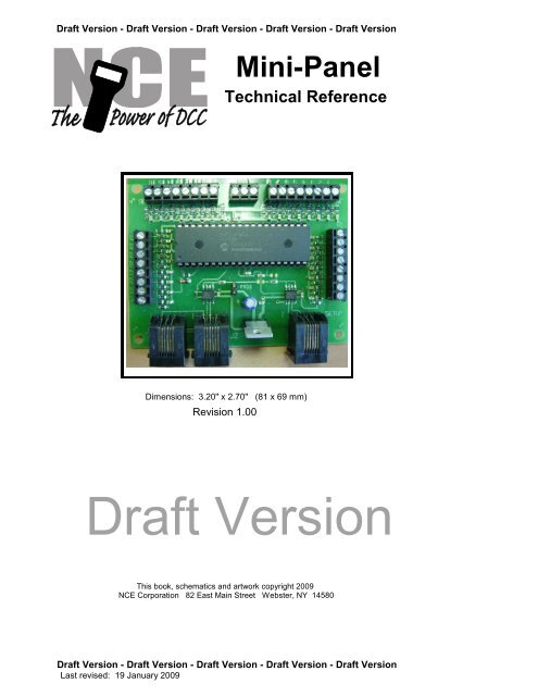
<strong>Mini</strong>-<strong>Panel</strong><br />
<strong>Technical</strong> <strong>Reference</strong><br />
Dimensions: 3.20" x 2.70" (81 x 69 mm)<br />
Revision 1.00<br />
Draft Version<br />
This book, schematics and artwork copyright 2009<br />
NCE Corporation 82 East Main Street Webster, NY 14580<br />
Draft Version - Draft Version - Draft Version - Draft Version - Draft Version<br />
Last revised: 19 January 2009
Draft Version - Draft Version - Draft Version - Draft Version - Draft Version<br />
Description of <strong>Mini</strong>-<strong>Panel</strong><br />
The mini-panel is primarily intended to make it easy to build control panels for yards,<br />
towns, interlockings and other layout applications. A secondary use of the panel is to<br />
provide rudimentary automation of trains or control of signals. For more complex<br />
automation or signal operation the Macro-panel has more comprehensive<br />
implementation of these secondary features and more memory for command storage.<br />
The mini panel has 30 inputs that can be connected to pushbuttons, toggle switches,<br />
block detectors, etc. for the purpose of issuing accessory, macro or locomotive control<br />
commands. A thirty-first input is provided to act as a panel reset. Activation of an<br />
input can initiate sending a string of DCC commands through the track to turnouts,<br />
locomotives, signals or other DCC controlled devices. Inputs are activated by<br />
connecting them to the mini panel “GROUND”. This makes the mini panel compatible<br />
with all pushbutton/toggle switches and most block detectors.<br />
The mini-panel communicates with the command station via the cab bus and uses one<br />
cab bus address.<br />
Setup (programming) of the mini-panel is accomplished by plugging a ProCab or NCE<br />
USB adapter into the “setup” jack. If USB is used the mini-panel memory is accessed<br />
via binary CV read and write commands (page or direct mode). USB jumpers should<br />
be set for PowerCab v1.28 or ALL SYS. CV7 and CV8 return the manufacturer<br />
number and version of the <strong>Mini</strong> <strong>Panel</strong> as with a decoder when used with the USB<br />
interface.<br />
Installation Notes:<br />
The mini panel runs off Cab Bus power (nominal 12V DC) and draws about 90mA of<br />
current, slightly less than a ProCab. NOTE: When used with the PowerCab use the<br />
mini panel default address of 3.<br />
Wiring:<br />
See the diagram below for sample wiring ideas.<br />
Plug in ProCab<br />
or USB interface<br />
for setup<br />
Push<br />
Button<br />
Push<br />
Button<br />
25 26 27 28 29 30 31 GND<br />
SETUP CAB BUS<br />
PIN 1<br />
1 2 3 4 5 6 7 8 GROUND 9 10 11 12 13 14 15 16<br />
1 2 3 4<br />
17 18 19 20 21 22 23 24<br />
BD20<br />
Block Detector<br />
Cab Bus<br />
can be<br />
daisy chained<br />
through the<br />
<strong>Mini</strong>-<strong>Panel</strong><br />
Toggle<br />
Switch<br />
Draft Version - Draft Version - Draft Version - Draft Version - Draft Version<br />
Last revised: 19 January 2009 Page 2
Draft Version - Draft Version - Draft Version - Draft Version - Draft Version<br />
<strong>Mini</strong> <strong>Panel</strong> Configuration Memory<br />
Location 0 - Cab bus address<br />
This is the Cab bus address useed by the <strong>Mini</strong>-<strong>Panel</strong> on the NCE Cab bus. The defualt<br />
address is 3. Setting this address to 0 will reset the <strong>Mini</strong>-<strong>Panel</strong> to factory defaults.<br />
Location 1 - Debounce timer<br />
Normally doesn't need to be changed. The value in this location determines how many<br />
cab bus "pings" (how many times the mini-panel is addressed on the cab bus) that an<br />
input must be grounded before the <strong>Mini</strong>-<strong>Panel</strong> recognizes it as a valid signal.<br />
Location 2 - For mat for display of unknown commands<br />
Memory location 2 controls whether (or not) the mini panel will display "unknown"<br />
commands in hex or decimal. A zero in location 2 means display in decimal, 1=hex.<br />
When using the USB interface (or the SETUP CONFIG menu) it is possible that<br />
command can get entered that the mini panel Review feature does not know how to<br />
display. In this case the mini panel will display the contents of these memory locations<br />
on the ProCab LCD screen as numeric values.<br />
Location 3 - Continuous Memory<br />
You can write fairly long automation sequences by constructing strings of 3 commands<br />
followed by a link to another string. This is inefficient in that only three out of four<br />
command locations in memory actually control anything.<br />
Memory location 3 can be programmed with an input number above which memory will<br />
be considered continuous. This means above that input number commands will<br />
continue to flow across each four command boundary and be executed until a<br />
terminating command of 0x00,0x00 is encountered.<br />
Remember that if any of those higher number inputs are grounded the associated<br />
commands starting at that input number will still be executed (unless memory location<br />
4 is programmed) and run until a termination command is encountered.<br />
Location 4 - Disabled inputs<br />
Memory location 4 can be programmed with the input number above which electrical<br />
status of those inputs will be ignored. Grounding one of those inputs will not result in<br />
execution of its command string. The input will still be used by the WAIT and SKIP<br />
commands that look at input status.<br />
Location 5 - Interrupting Wait Commands<br />
Wait commands will loop until the input condition is met. No other operations of the<br />
mini panel will be performed while waiting so the panel will appear dead. It is quite<br />
possible that situations on the layout will occur that upset the flow of your automation<br />
‘program’. Imagine that the program is waiting for a loco to get to a certain block and a<br />
derailment occurs causing the train to stop. The loco is replaced on the track but on a<br />
parallel track resulting in the loco never getting to the block that the program is<br />
expecting to be occupied. The mini panel will wait forever appearing to be<br />
unresponsive. You can utilize an unused input of the mini-panel as an ‘interrupt’ to<br />
break the mini panel out of this wait forever loop and continue normal operations.<br />
Program memory location 5 with the input number you want to use as the interrupt. By<br />
connection a pushbutton to this input you can provide a recovery mechanism without<br />
resetting the entire panel, losing turnout positions, signal aspects or loco function<br />
states.<br />
Location 6 -<br />
Memory location 6 is unused.<br />
Location 7 -<br />
Memory location 7 is unused.<br />
Draft Version - Draft Version - Draft Version - Draft Version - Draft Version<br />
Last revised: 19 January 2009 Page 3
Draft Version - Draft Version - Draft Version - Draft Version - Draft Version<br />
To set up the <strong>Mini</strong> <strong>Panel</strong> plug a ProCab into the "SETUP" jack of the <strong>Mini</strong> <strong>Panel</strong>, make<br />
sure the Cab Bus is connected from the <strong>Mini</strong> <strong>Panel</strong> to the NCE DCC system and turn<br />
the power for the system on.<br />
The mini panel will detect the presence of the ProCab and you should see an opening<br />
LCD display of:<br />
NCE NCE MINI-PANEL<br />
MINI-PANEL<br />
VERSION VERSION 1.00<br />
1.00<br />
Press ENTER on the ProCab to get the main display for panel setup<br />
1=SETUP 2=MACRO<br />
3=TEST OPERATION<br />
We want to setup the panel so press "1" to enter setup mode, this will present the<br />
display screen as below<br />
Press "1" to setup an INPUT.<br />
SETUP MINI PANEL<br />
1=INPUT 2=CONFIG<br />
SETUP INPUT MENU<br />
INPUT NUMBER: 01<br />
We will start programming the inputs with input number 1. Type “1” followed by<br />
“ENTER” to program input number 1<br />
SETUP INPUT MENU<br />
STEP NUMBER: 1<br />
Normally when setting up an input we start with step number 1. We want to start<br />
programming at step 1 so just press ENTER to accept that step. Commands will be<br />
sent from the <strong>Mini</strong> <strong>Panel</strong> in order of their step number until an ‘empty’ step is<br />
encountered or four steps are completed.<br />
INP: 01 STEP: 1<br />
1=ACCY 2=MACRO<br />
At this point we’re ready to tell the mini panel exactly which command to send when<br />
button 1 is pushed. Press “1” to send an accessory command.<br />
INP: 01 STEP: 1<br />
ACCY NUMBER:<br />
Type the accessory number “1” followed by “ENTER”. Allowable NMRA accessory<br />
addresses are 1-2044. Accessory number 2044 is the broadcast address for<br />
accessories. There is no accessory address 0.<br />
INP: 01 STEP: 1<br />
1=NORM 2=REV<br />
Press “1” to send the accessory command for Normal when button 1 is pressed.<br />
INP: 01 STEP: 2<br />
1=ACCY 2=MACRO<br />
Draft Version - Draft Version - Draft Version - Draft Version - Draft Version<br />
Last revised: 19 January 2009 Page 4
Draft Version - Draft Version - Draft Version - Draft Version - Draft Version<br />
Note that the step number has increased to 2 indicating the last command has been<br />
accepted and the <strong>Mini</strong> <strong>Panel</strong> is ready for the next command for this input. We don’t<br />
need any more commands for this input so press “PROG/ESC” to return to the main<br />
menu.<br />
1=SETUP 2=MACRO<br />
3=TEST OPERATION<br />
Let’s review the command that has just been programmed. Press “2” to review.<br />
1=SETUP 2=REVIEW<br />
REVIEW INPUT:<br />
Type “1” and press “ENTER” to review the command sent by input number 1<br />
INP: 01 STEP: 1<br />
ACCY: 001 NORM<br />
The LCD no displays the accessory number (1) that we entered and the turnout<br />
position (Normal). Press “ENTER” to see the next step for this input<br />
INP: 01 STEP: 2<br />
--END--<br />
The display now indicates that there are no more entries programmed into this string.<br />
At this point you may continue pressing “ENTER” to cycle up through all the commands<br />
programmed if you wish. The Input and step numbers will be displayed as well as a<br />
description of the command for that step. Press “PROG/ESC” to return to the main<br />
menu.<br />
1=SETUP 2=MACRO<br />
3=TEST OPERATION<br />
At this point we have programmed and reviewed the command(s) that will be sent<br />
when input number 1 is grounded. The command can be tested by pressing “3”.<br />
TESTING<br />
INPUT NUMBER: 01<br />
Press “1” followed by “ENTER” to test input 1. The command string associated with<br />
input number 1 will be sent.<br />
1=SETUP 2=MACRO<br />
3=TEST OPERATION<br />
Putting the <strong>Mini</strong> <strong>Panel</strong> into test mode will also allow testing of any input by grounding<br />
that input number. Pressing any button on the ProCab will return the <strong>Mini</strong> <strong>Panel</strong> to<br />
setup mode.<br />
Finishing programing:<br />
At this point we have programmed, reviewed and tested the command(s) that will be<br />
sent when input number 1 is grounded. In a similar manner we can program the<br />
commands for inputs 2,3 and 4 using the proper accessory or macro commands.<br />
Draft Version - Draft Version - Draft Version - Draft Version - Draft Version<br />
Last revised: 19 January 2009 Page 5
Draft Version - Draft Version - Draft Version - Draft Version - Draft Version<br />
MAIN MENU<br />
MENU NAVIGATION CHART<br />
2 3<br />
REVIEW<br />
TEST<br />
1<br />
SETUP<br />
2<br />
SETUP CONFIG INPUT #<br />
INPUT #<br />
1<br />
SETUP INPUT<br />
CAB ADDRESS<br />
INPUT #<br />
MEM ADDRESS<br />
STEP #<br />
MEMORY DATA<br />
5<br />
OTHER<br />
4<br />
SIGNAL<br />
3<br />
LOCO<br />
2<br />
MACRO<br />
1<br />
ACCY<br />
SIGNAL #<br />
MACRO #<br />
ACCY #<br />
Draft Version - Draft Version - Draft Version - Draft Version - Draft Version<br />
Last revised: 19 January 2009 Page 6<br />
ASPECT<br />
3<br />
FUNCTIONS<br />
2<br />
SPEED<br />
1<br />
SELECT<br />
NORM or REV<br />
LOCO #<br />
2<br />
F5-F8<br />
1<br />
F0-F4<br />
2<br />
28 MODE<br />
1<br />
128 MODE<br />
SPEED VAL<br />
SPEED VAL<br />
DIRECTION<br />
DIRECTION<br />
6<br />
SKIP<br />
5<br />
ADD NOP<br />
4<br />
OPS PROG LOC<br />
3<br />
LINK<br />
2<br />
WAIT<br />
1<br />
DELAYS<br />
CV #<br />
INPUT #<br />
2<br />
OPEN<br />
1<br />
GROUND<br />
2<br />
OPEN<br />
1<br />
GROUND<br />
2<br />
1/4 SECs<br />
1<br />
4 SECs<br />
DATA<br />
INPUT #<br />
INPUT #<br />
# #
Draft Version - Draft Version - Draft Version - Draft Version - Draft Version<br />
Command Descriptions:<br />
The following commands can be setup through the ProCab user interface and sent by<br />
the <strong>Mini</strong> <strong>Panel</strong>:<br />
Accessory/Macro commands<br />
� Accessory Command - all NMRA standard accessory addresses (1-2044) can be<br />
sent via the accessory command. There is no address 0. Address 2044 is the<br />
boradcast addresss.<br />
� Macro command - all NCE macro numbers (0-255) can be sent via the Macro<br />
command.<br />
Locomotive commands<br />
Speed and functions may be controlled<br />
� Select loco - A locomotive must be selected before any commands can be sent to<br />
that loco. Any NMRA standard locomotive address (up to 9999) may be selected.<br />
Short addresses fro 1-127 and long addresses 0-9999 are all valid and are entered<br />
in the same manner as they are selected in normal operations with a Pro/Power<br />
Cab. A leading zero before and address in the range of 1-127 indicates a long<br />
address. Once a loco address is selected all speed, function and Ops programing<br />
commands will be sent to that address unless another address is selected.<br />
� Speed commands - Both 28 and 128 speed mode commands can be sent. Once<br />
the speed is entered the direction can be changed by pushing the “DIRECTION”<br />
button.<br />
� Function commands - Function commands for F0-F8 can be sent. Due to the way<br />
the NMRA has defined function operation, functions are not controlled individually<br />
but are controlled in groups of four or five (or eight) at once. The state of F0-F4<br />
(function group 1) must be sent as one command while the state of F5-F8 (function<br />
group 2) is as a different command. When you choose the ‘Function’ option from<br />
the Loco commands Menu you must choose which function group you want to<br />
control<br />
ENTER FUNC GROUP<br />
1=F0-F4 2=F5-F8<br />
Once the group is selected you can select which functions in that group are to be<br />
on or off.<br />
PRESS F NUMBER<br />
DIGITS 0-4:-----<br />
In the case of function group 1 (LCD display above) pressing a digit of 0-4 will<br />
toggle that function on/off. If a digit is displayed the function will be on of a<br />
dash (“-”) is displayed the function will be off.<br />
PRESS F NUMBER<br />
DIGITS 0-4:0-23-<br />
In the display above F0 (headlight),F2 and F3 will be on and F1, F4 will be off.<br />
Signal commands<br />
� Signal Command - all NMRA standard signal addresses (1-2044) can be controlled<br />
via the signal command. Aspects are limited to the first 8 aspects (0-7). The<br />
signal commands are the NMRA standard signal commands using NMRA standard<br />
signal control packets. There is no address 0. Address 2044 is the broadcast<br />
address.<br />
Draft Version - Draft Version - Draft Version - Draft Version - Draft Version<br />
Last revised: 19 January 2009 Page 7
Draft Version - Draft Version - Draft Version - Draft Version - Draft Version<br />
Other commands<br />
There are 6 groups of ‘other’ commands executed by the <strong>Mini</strong> <strong>Panel</strong>. These<br />
commands do not result in a DCC command being sent but control the flow of the<br />
commands from the <strong>Mini</strong> <strong>Panel</strong>.<br />
� Delays - Two different delay commands can be used. These commands will cause<br />
the <strong>Mini</strong> <strong>Panel</strong> to delay execution of the next command in increments of ¼ second<br />
(up to 64 seconds total delay) or increments of 4 seconds (up to 1020 seconds<br />
total delay). A delay of 0 will cause the next command to be executed immediately.<br />
Use of this command causes all operation of the <strong>Mini</strong> <strong>Panel</strong> to stop while the<br />
command is in progress.<br />
� Wait - There are two Wait commands, one command waits for a indicated input to<br />
be grounded, the other waits for the indicated input to become ungrounded (open).<br />
Use of this command causes all operation of the <strong>Mini</strong> <strong>Panel</strong> to stop while the<br />
command is in progress.<br />
� Link - Use of this command will transfer operation to the string of four commands<br />
associated with another input.<br />
� Skip -There are two commands that can be used to make a decision based on the<br />
status of an input. These commands check the status of a user indicated input<br />
and either execute the next command in the string or skip over that command and<br />
execute the following command. One skip command skips if the indicated input is<br />
grounded the other skips if the input is ungrounded (open). These are very<br />
powerful commands allowing the <strong>Mini</strong> <strong>Panel</strong> to execute different commands based<br />
on the state of an input at the time the skip command is executed.<br />
� Nop - The No-Operation command. This command can be used as a place holder<br />
for future commands. When the <strong>Mini</strong> panel encounters this command in the<br />
command string it will be ignored and the next command will be executed.<br />
� CV Program - Allows programming of locomotive CVs in Ops mode. OPs mode<br />
programming requires 3 steps:<br />
set loco address (long or short)<br />
set CV number<br />
set CV data<br />
When the data command is executed an Ops programming command will be<br />
issued out over the cab bus to the track.<br />
<strong>Technical</strong> stuff:<br />
Linking command strings<br />
Inputs cannot normally be “decoupled” from their command string. If you link to the<br />
command string of an input that is connected to something that may activate that input,<br />
the commands for that input will be executed when the input is grounded. In some<br />
circumstances this may be desirable allowing portions of larger, longer command<br />
strings to be used. Normally you will want to leave linked inputs electrically<br />
unconnected.<br />
OPs programming command<br />
OPs mode programming requires 3 steps:<br />
set loco address (long or short)<br />
set CV number<br />
set CV data<br />
When the data is set the programming command will be issued out over the cab bus to<br />
the track. If the loco address has already been set in a previous command that<br />
address will be used. The same applies to the CV number. You can use this to your<br />
advantage to program momentum using the (3 required steps) into a locomotive then<br />
later just programming a new momentum value using only the set CV data command.<br />
Command string terminator<br />
When the mini panel encounters the command 0x00,0x00 it is considered the<br />
command string terminator. Any commands following the terminator in the string will<br />
not be executed.<br />
Input scanning<br />
Draft Version - Draft Version - Draft Version - Draft Version - Draft Version<br />
Last revised: 19 January 2009 Page 8
Draft Version - Draft Version - Draft Version - Draft Version - Draft Version<br />
The inputs of the <strong>Mini</strong>-panel are scanned in numerical order. Inputs are sampled in<br />
groups of 8 and stored in temporary memory. This group is then scanned for active<br />
inputs. An input at or near ground potential is considered active. When an input is<br />
transitions from open (high due to 5v pull-up resistor) to ground (low) it will trigger<br />
execution of a string of up to four commands associated with that input. Transitions<br />
from low to high are ignored and no action is performed.<br />
The lowest numbered active input of the group of eight is acted upon first. The<br />
command string associated with that input will be executed. Execution of the<br />
command string will continue until a command of 0x00,0x00 is encountered or until 4<br />
commands are executed.<br />
One exception to the four command limit is the “link” command that transfers execution<br />
to another input command string. This allows borrowing the memory location from<br />
other (possibly) unused inputs to create longer strings of commands. The memory<br />
space for the unused input can be used by another command string.<br />
Once a command string has completed execution the next active input will be located<br />
and its command string executed.<br />
After a group of 8 inputs is scanned and any active inputs are serviced the next group<br />
of 8 inputs will be sampled.<br />
Inputs are captured eight at a time and actions generated by those 8 inputs are<br />
completed before capturing the next higher group of eight. If an input of one group of 8<br />
initiates a long string of commands (see linking below) that will take a significant period<br />
of time is it possible to miss momentarily activated inputs. This is not a problem for<br />
typical applications with quick acting command strings such those used with a control<br />
panel that just issues accessory/macro commands. The problem may occur in layout<br />
automation applications that require long periods of time waiting for a loco to enter a<br />
block or delays used for stopping at a station. In these cases you must carefulyl<br />
consider the series of event that may be happening and how commands are strung<br />
together.<br />
USB interface<br />
When using the NCE USB interface memory locations 1-255 can be read or written<br />
using programming track direct mode binary commands 0xa8 and 0xa9. It is<br />
necessary to put the USB interface into program track mode with the 0x9e command<br />
before attempting programming other wise you will just get the “not in program track<br />
mode” response from the USB interface. This will allow you to test the commands you<br />
just programmed without having to disconnect the USB interface. You cannot read<br />
memory location 0 (Cab Bus address). Memory locations 6 (ver) and 7 (mfr) allow<br />
you to determine the <strong>Mini</strong> <strong>Panel</strong> manufacturer and software version. <strong>Mini</strong> panel<br />
software versions start at 200 (decimal) and the manufacturer is 11 decimal (NCE).<br />
You may still write memory locations 6 and 7 but not read them through the USB<br />
interface. They are trapped by the mini panel software when the USB is used for<br />
reading with the manufacturer and version substituted for the actual values in memory.<br />
You can read them by plugging a ProCab into the SETUP port.<br />
When using Decoder Pro for programming select:<br />
Service mode programming<br />
Comprehensive Programmer format<br />
NMRA<br />
Raw CVs 1-255<br />
Click on “READ” for CV1. Due to multiple layers of buffering between the USB and<br />
<strong>Mini</strong> <strong>Panel</strong> the first CV read will fail but you should get valid reads and writes from that<br />
point on. Using Direct Byte mode is slightly faster than Paged mode.<br />
When finished programming you can put the <strong>Mini</strong> <strong>Panel</strong> back into operational mode<br />
with the 0xa6 (Write register) command. Any register and value is OK. The panel is<br />
just looking for any Write Register command<br />
Draft Version - Draft Version - Draft Version - Draft Version - Draft Version<br />
Last revised: 19 January 2009 Page 9
Draft Version - Draft Version - Draft Version - Draft Version - Draft Version<br />
Gotchas<br />
� Any and all commands for Input 31 will be executed before the mini panel tries to<br />
detect a ProCab plugged into the SETUP port. If you have an automation program<br />
that begins at power up the ProCab will not be detected for setup until the program<br />
completes. If the program doesn’t complete (“wait forever” etc) you will not be able<br />
to access the setup menus. Workaround: You can force the <strong>Mini</strong> <strong>Panel</strong> into setup<br />
mode by installing the “PROG” jumper. It is best to remove the jumper as soon as<br />
you get into setup mode as the jumper shorts out the mini panel internal Cab Bus<br />
receive line. The mini panel chips should be protected against this short but it’s best<br />
to not tempt fate.<br />
�<br />
Draft Version - Draft Version - Draft Version - Draft Version - Draft Version<br />
Last revised: 19 January 2009 Page 10
Draft Version - Draft Version - Draft Version - Draft Version - Draft Version<br />
Command format of the <strong>Mini</strong> <strong>Panel</strong><br />
The table below describes the hex bytes stored in the memory locations for each command<br />
Hex 1st Byte 2nd Byte Command<br />
0x00 0000 0000 0000 0000 command string terminator - stop<br />
execution<br />
00->07 0000 0aaa aaaa aaaa accessory on(N) 1->2044, addr 0 not<br />
valid<br />
08->0f 0000 1aaa aaaa aaaa accessory off(R) 1->2044, addr 0 not<br />
valid<br />
40->7f 01nn naaa aaaa aaaa signal 1-2044 aspect 0-7, addr 0 not<br />
valid<br />
80->b7 10aa aaaa aaaa aaaa set long loco address 0-10239<br />
b8-bb 1011 10nn nnnn nnnn set OPs CV num. 1-1024 (set loco/accy<br />
addr 1st)<br />
bc 1011 1100 dddd dddd set OPs loco CV data (set CV number<br />
first)<br />
bd 1011 1101 dddd dddd set OPs accy CV data (set CV number<br />
first)<br />
be 1011 1110 dddd dddd set OPs signal CV data (set CV number<br />
first)<br />
bf 1011 1111 nnnn nnnn delay in 4 second increments<br />
c0 1100 0000 0sss ssss stored loco 128 speed reverse<br />
c0 1100 0000 1sss ssss stored loco 128 speed forward<br />
c1 1100 0001 000s ssss stored loco 28 speed reverse (0-28<br />
valid)<br />
c1 1100 0001 001s ssss stored loco 28 speed forward (0-28<br />
valid)<br />
c1 1100 0001 010f ffff function group 1 f0,f4,f3,f2,f1<br />
c1 1100 0001 0110 ffff function group 2 f8,f7,f6,f5<br />
c1 1100 0001 0111 ffff function group 3 f12,f11,f10,f9<br />
c1 1100 0001 1aaa aaaa set short loco address<br />
c2 1100 0010 ffff ffff f20->f13<br />
c3 1100 0011 ffff ffff f28->f21<br />
c4 1100 0011 nnnn nnnn loco detected in block 0-255<br />
c5 1100 0101 nnnn nnnn delay in 1/4 second increments<br />
c6 1100 0110 000n nnnn wait until input nnnnn active, 0 not<br />
valid<br />
c6 1100 0110 001n nnnn wait until input nnnnn not active, 0<br />
not valid<br />
c6 1100 0110 010n nnnn link to execute commands for input<br />
nnnnn<br />
c6 1100 0110 011x xxxx unused<br />
c6 1100 0110 100n nnnn if input nnnnn active skip the next<br />
command<br />
c6 1100 0110 101n nnnn if input nnnnn not active skip the<br />
next command<br />
c6 1100 0110 11xx xxxx not used<br />
c7 1100 0111 nnnn nnnn macro 0-255<br />
c8-cf 1100 1aaa aaaa aaaa set accessory/signal address 1-2044<br />
d0-fe ---- ---- ---- ---- unused<br />
ff<br />
Key:<br />
1111 1111 1111 1111 nop - no-operation, just execute next<br />
command<br />
a - address bit, f - function bit, n - number, s - speed data, x - undefined<br />
Notes:<br />
Commands bf and c5 block reading/execution of all inputs until time expires<br />
The wait commands of c6 block reading of all other inputs until condition is met<br />
The “skip” commands of c6 work in “real time” (right now) and do not wait or block other<br />
commands<br />
Once the loco address is set all subsequent locomotive commands will be sent to that address.<br />
Once the accy or signal address is set all subsequent OPs programming commands will be sent<br />
to that address<br />
Due to memory limitations the 0xbd,0xbe,0xc2, 0xc3, 0xc8 and 0xc6 function group 3<br />
commands are not available through the ProCab setup interface. They are available for use<br />
through the USB interface.<br />
Draft Version - Draft Version - Draft Version - Draft Version - Draft Version<br />
Last revised: 19 January 2009 Page 11
Chart of <strong>Mini</strong> <strong>Panel</strong> memory locations<br />
4<br />
15<br />
7e/7f<br />
126/127<br />
3<br />
15<br />
7c/7d<br />
124/125<br />
2<br />
15<br />
7a/7b<br />
122/123<br />
1<br />
15<br />
78/79<br />
120/121<br />
4<br />
31<br />
fe/ff<br />
254/255<br />
4<br />
14<br />
76/77<br />
118/119<br />
3<br />
31<br />
fc/fd<br />
252/253<br />
3<br />
14<br />
74/75<br />
116/117<br />
2<br />
31<br />
fa/fb<br />
250/251<br />
2<br />
14<br />
72/73<br />
114/115<br />
1<br />
31<br />
f8/f9<br />
248/249<br />
1<br />
14<br />
70/71<br />
112/113<br />
4<br />
30<br />
f6/f7<br />
246/247<br />
4<br />
13<br />
6e/6f<br />
110/111<br />
3<br />
30<br />
f4/f5<br />
244/245<br />
3<br />
13<br />
6c/6d<br />
108/109<br />
2<br />
30<br />
f2/f3<br />
242/243<br />
2<br />
13<br />
6a/6b<br />
106/107<br />
1<br />
30<br />
f0/f1<br />
240/241<br />
1<br />
13<br />
68/69<br />
104/105<br />
4<br />
30<br />
ee/ef<br />
238/239<br />
4<br />
12<br />
66/67<br />
102/103<br />
3<br />
29<br />
ec/ed<br />
236/237<br />
3<br />
12<br />
64/65<br />
100/101<br />
2<br />
29<br />
ea/eb<br />
234/235<br />
2<br />
12<br />
62/63<br />
98/99<br />
1<br />
29<br />
e8/e9<br />
232/233<br />
1<br />
12<br />
60/61<br />
96/97<br />
4<br />
29<br />
e6/e7<br />
230/231<br />
4<br />
11<br />
5e/5f<br />
94/95<br />
3<br />
28<br />
e4/e5<br />
228/229<br />
3<br />
11<br />
5c/5d<br />
92/93<br />
2<br />
28<br />
e2/e3<br />
226/227<br />
2<br />
11<br />
5a/5b<br />
90/91<br />
1<br />
28<br />
e0/e1<br />
224/225<br />
1<br />
11<br />
58/59<br />
88/89<br />
4<br />
27<br />
de/df<br />
222/223<br />
4<br />
10<br />
56/57<br />
86/87<br />
3<br />
27<br />
dc/dd<br />
220/221<br />
3<br />
10<br />
54/55<br />
84/85<br />
2<br />
27<br />
da/db<br />
218/219<br />
2<br />
10<br />
52/53<br />
82/83<br />
1<br />
27<br />
d8/d9<br />
216/217<br />
1<br />
10<br />
50/51<br />
80/81<br />
4<br />
26<br />
d6/d7<br />
214/215<br />
4<br />
9<br />
4e/4f<br />
78/79<br />
3<br />
26<br />
d4/d5<br />
212/213<br />
3<br />
9<br />
4c/4d<br />
76/77<br />
2<br />
26<br />
d2/d3<br />
210/211<br />
2<br />
9<br />
4a/4b<br />
74/75<br />
1<br />
26<br />
d0/d1<br />
208/209<br />
1<br />
9<br />
48/49<br />
72/73<br />
4<br />
25<br />
ce/cf<br />
206/207<br />
4<br />
8<br />
46/47<br />
70/71<br />
3<br />
25<br />
cc/cd<br />
204/205<br />
3<br />
8<br />
44/45<br />
68/69<br />
2<br />
25<br />
ca/cb<br />
202/203<br />
2<br />
8<br />
42/43<br />
66/67<br />
1<br />
25<br />
c8/c9<br />
200/201<br />
1<br />
8<br />
40/41<br />
64/65<br />
4<br />
24<br />
c6/c7<br />
198/199<br />
4<br />
7<br />
3e/3f<br />
62/63<br />
3<br />
24<br />
c4/c5<br />
196/197<br />
3<br />
7<br />
3c/3d<br />
60/61<br />
2<br />
24<br />
c2/c3<br />
194/195<br />
2<br />
7<br />
3a/3b<br />
58/59<br />
1<br />
24<br />
c0/c1<br />
192/193<br />
1<br />
7<br />
38/39<br />
56/57<br />
4<br />
23<br />
be/bf<br />
190/191<br />
4<br />
6<br />
36/37<br />
54/55<br />
3<br />
23<br />
bc/bd<br />
188/189<br />
3<br />
6<br />
34/35<br />
52/53<br />
2<br />
23<br />
ba/bb<br />
186/187<br />
2<br />
6<br />
32/33<br />
50/51<br />
1<br />
23<br />
b8/b9<br />
184/185<br />
1<br />
6<br />
30/31<br />
48/49<br />
4<br />
22<br />
b6/b7<br />
182/183<br />
4<br />
5<br />
2e/2f<br />
46/47<br />
3<br />
22<br />
b4/b5<br />
180/181<br />
3<br />
5<br />
2c/2d<br />
44/45<br />
2<br />
22<br />
b2/b3<br />
178/179<br />
2<br />
5<br />
2a/2b<br />
42/43<br />
1<br />
22<br />
b0/b1<br />
176/177<br />
1<br />
5<br />
28/29<br />
40/41<br />
4<br />
21<br />
ae/af<br />
174/175<br />
4<br />
4<br />
26/27<br />
38/39<br />
3<br />
21<br />
ac/ad<br />
172/173<br />
3<br />
4<br />
24/25<br />
36/37<br />
2<br />
21<br />
aa/ab<br />
170/171<br />
2<br />
4<br />
22/23<br />
34/35<br />
1<br />
21<br />
a8/a9<br />
168/169<br />
1<br />
4<br />
20/21<br />
32/33<br />
4<br />
20<br />
a6/a7<br />
166/167<br />
4<br />
3<br />
1e/1f<br />
30/31<br />
3<br />
20<br />
a4/a5<br />
164/165<br />
3<br />
3<br />
1c/1d<br />
28/29<br />
2<br />
20<br />
a2/a3<br />
162/163<br />
2<br />
3<br />
1a/1b<br />
26/27<br />
1<br />
20<br />
a0/a1<br />
160/161<br />
1<br />
3<br />
18/19<br />
24/25<br />
4<br />
19<br />
9e/9f<br />
158/159<br />
4<br />
2<br />
16/17<br />
22/23<br />
3<br />
19<br />
9c/9d<br />
156/157<br />
3<br />
2<br />
14/15<br />
20/21<br />
2<br />
19<br />
9a/9b<br />
154/155<br />
2<br />
2<br />
12/13<br />
18/19<br />
1<br />
19<br />
98/99<br />
152/153<br />
1<br />
2<br />
10/11<br />
16/17<br />
4<br />
18<br />
96/97<br />
150/151<br />
4<br />
1<br />
0e/0f<br />
14/15<br />
3<br />
18<br />
94/95<br />
148/149<br />
3<br />
1<br />
0c/0d<br />
12/13<br />
2<br />
18<br />
92/93<br />
146/147<br />
2<br />
1<br />
0a/0b<br />
10/11<br />
1<br />
18<br />
90/91<br />
144/145<br />
1<br />
1<br />
08/09<br />
8/9<br />
4<br />
17<br />
8e/8f<br />
142/143<br />
---<br />
0x07<br />
7<br />
3<br />
17<br />
8c/8d<br />
140/141<br />
---<br />
0x06<br />
6<br />
2<br />
17<br />
8a/8b<br />
138/139<br />
“Wait” Interrupt<br />
0x05<br />
5<br />
1<br />
17<br />
88/89<br />
136/137<br />
Dead inputs<br />
0x04<br />
4<br />
4<br />
16<br />
86/87<br />
134/135<br />
Continuous mem<br />
0x03<br />
3<br />
3<br />
16<br />
84/85<br />
132/133<br />
Clear 8 mem loc<br />
0x02<br />
2<br />
2<br />
16<br />
82/83<br />
130/131<br />
Debounce<br />
0x01<br />
1<br />
1<br />
16<br />
80/81<br />
128/129<br />
Cab Bus Addr<br />
0x00<br />
0<br />
Step #<br />
INP #<br />
Hex<br />
Decimal<br />
Step #<br />
INP #<br />
Hex<br />
Decimal<br />
Description<br />
Memory location<br />
Description<br />
Memory location<br />
Draft Version - Draft Version - Draft Version - Draft Version - Draft Version<br />
Draft Version - Draft Version - Draft Version - Draft Version - Draft Version<br />
Last revised: 19 January 2009 Page 12
Draft Version - Draft Version - Draft Version - Draft Version - Draft Version<br />
Default values for memory locations<br />
Location 0 - 3 Cab bus address, 2-63 are OK<br />
Location 1 - 5 Debounce timer (normally doesn’t ever need change)<br />
Location 2 - 0 Clear all 8 memory locations for an input when programming 1=don’t<br />
Location 3 - 0 Input number at/above which command string memory is continuous<br />
Location 4 - 0 Input number at/above which commands will not execute if input active<br />
Location 5 - 0 Input number than can be used to interrupt “wait” commands<br />
Location 6 - Unused (Software version 201 when read via USB - CV7)<br />
Location 7 - Unused (Manufacturer 11 when read via USB - CV8)<br />
Locations 8 through 255 - 0<br />
Warning: This product contains chemicals known to the State of<br />
California to cause cancer, birth defects or other reproductive harm.<br />
Warranty<br />
This product is fully factory tested and warranted against manufacturing defects for a<br />
period of 1 year. As the circumstances under which this product is installed can not be<br />
controlled, failure due to installation problems can not be warranted. This includes<br />
misuse, miswiring, operation under loads or voltages beyond the design range of the<br />
product.<br />
For warranty or non-warranty repair/replacement send the product (an any payment, if<br />
required) to:<br />
NCE Warranty Center 82 East Main St. Webster, New York 14580<br />
The terms Silent Running, Power Pro, PowerCab , ProCab, Switch-It the NCE logo with “Power of DCC” slogan are trademarks of<br />
NCE Corporation. The distinctive shape of the ProCab when used with a thumbwheel speed control and LCD display is a<br />
trademark of NCE Corporation.<br />
Draft Version - Draft Version - Draft Version - Draft Version - Draft Version<br />
Last revised: 19 January 2009 Page 13