Digital Modulation Techniques in Mobile Communications
Digital Modulation Techniques in Mobile Communications
Digital Modulation Techniques in Mobile Communications

You also want an ePaper? Increase the reach of your titles
YUMPU automatically turns print PDFs into web optimized ePapers that Google loves.
<strong>Digital</strong> <strong>Modulation</strong> <strong>Techniques</strong> <strong>in</strong><strong>Mobile</strong> <strong>Communications</strong>Fahredd'n Sadikoglu 1
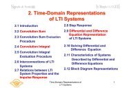
<strong>Digital</strong> <strong>Modulation</strong> TechniqueSender Dest<strong>in</strong>ationMessageMessage<strong>Modulation</strong>Channel DemodulationFahredd'n Sadikoglu 2
<strong>Modulation</strong> <strong>Techniques</strong>• <strong>Modulation</strong> is the process of encod<strong>in</strong>g <strong>in</strong>formation from amessage source <strong>in</strong> a manner suitable for transmition.• The ultimate goal of a modulation technique is to transport themessage signal through a radio channel with the best possiblequality while occupy<strong>in</strong>g the least amount of radio spectrum.SenderMessage <strong>Modulation</strong> ChannelD(t)C(t)=A COS (wt+Φ)Fahredd'n Sadikoglu 3
• <strong>Modulation</strong> may be done by vary<strong>in</strong>g the amplitude,phase, or frequency of a high frequency carrier <strong>in</strong>accordance with the amplitude of the messagesignal.C(t)=A COS (wt+Φ)ASK FSK PSK
Amplitude Shift Key<strong>in</strong>g (ASK)- Pulse shap<strong>in</strong>g can be employed to remove spectralspread<strong>in</strong>g.- ASK demonstrates poor performance, as it is heavilyaffected by noise and <strong>in</strong>terference.
Frequency Shift Key<strong>in</strong>g (FSK)- Bandwidth occupancy of FSK is dependant on the spac<strong>in</strong>g of thetwo symbols. A frequency spac<strong>in</strong>g of 0.5 times the symbol periodis typically used.- FSK can be expanded to a M-ary scheme, employ<strong>in</strong>g multiplefrequencies as different states.-
Phase Shift Key<strong>in</strong>g (PSK)- B<strong>in</strong>ary Phase Shift Key<strong>in</strong>g (BPSK) demonstrates better performancethan ASK and FSK.- PSK can be expanded to a M-ary scheme, employ<strong>in</strong>g multiple phasesand amplitudes as different states.- Filter<strong>in</strong>g can be employed to avoid spectral spread<strong>in</strong>g.
PSK & DPSKFahredd'n Sadikoglu 8
Multi-PhaseB<strong>in</strong>ary Phase ShiftKey<strong>in</strong>g (BPSK)1: φ 1 (t)= p(t) cos(ω c t)••0: φ 0 (t)= p(t)cos(ω c t+π)M-ary PSK⎛ 2π⎞pk() t = p()t cos⎜ωct+k⎟⎝ M ⎠xxxxxxImImxxxxReReFahredd'n Sadikoglu 9
QPSK* Quadrature Phase Shift Key<strong>in</strong>g is effectively two <strong>in</strong>dependentBPSK systems (I and Q), and therefore exhibits the sameperformance but twice the bandwidth efficiency.* Quadrature Phase Shift Key<strong>in</strong>g can be filtered us<strong>in</strong>g raisedcos<strong>in</strong>e filters to achieve excellent out of band suppression.* Large envelope variations occur dur<strong>in</strong>g phase transitions, thusrequir<strong>in</strong>g l<strong>in</strong>ear amplification.
Quadrature Phase-Shift Key<strong>in</strong>g(QPSK)Constellation diagram for •QPSK with Gray cod<strong>in</strong>g.Each adjacent symbol onlydiffers by one bit.QPSK can encode two bits •per symbol, shown <strong>in</strong> thediagram with Gray cod<strong>in</strong>g tom<strong>in</strong>imize the BER twice therate of BPSK.QPSK may be used either todouble the data ratecompared to a BPSK systemwhile ma<strong>in</strong>ta<strong>in</strong><strong>in</strong>g thebandwidth of the signal orto ma<strong>in</strong>ta<strong>in</strong> the data-rate ofBPSK but halve thebandwidth needed.•Fahredd'n Sadikoglu 11
• Constellation diagram for QPSKwith Gray cod<strong>in</strong>g. Each adjacentsymbol only differs by one bit.• QPSK can encode two bits persymbol, shown <strong>in</strong> the diagramwith Gray cod<strong>in</strong>g to m<strong>in</strong>imize theBER twice the rate of BPSK.• QPSK may be used either todouble the data rate comparedto a BPSK system whilema<strong>in</strong>ta<strong>in</strong><strong>in</strong>g the bandwidth of thesignal or to ma<strong>in</strong>ta<strong>in</strong> the datarateof BPSK but halve thebandwidth needed.
QPSKModeled as two BPSK systems <strong>in</strong>parallel•Imx0 1 1 1 0 0 1 0Serial toParallelConverterR b1 1 0 0R b /20 1 0 1xR b /2cos ω c t90xT s =2 T b-+ BPF•xxxReFahredd'n Sadikoglu 13
• The b<strong>in</strong>ary data that is conveyed by this waveform is: 1 1 0 0 0 1 1 0.• The odd bits, highlighted here, contribute to the <strong>in</strong>-phase component:1 1 0 0 0 1 1 0. The even bits, highlighted here, contribute to thequadrature-phase component: 1 1 0 0 0 1 1 0 .• In the tim<strong>in</strong>g diagram for QPSK. The b<strong>in</strong>ary data stream is shownbeneath the time axis. The two signal components with their bitassignments are shown the top and the total, comb<strong>in</strong>ed signal at thebottom. Note the abrupt changes <strong>in</strong> phase at some of the bit-periodboundaries which are not satisfied.
QPSK TYPESFahredd'n Sadikoglu 15
QPSKFahredd'n Sadikoglu 16
Fahredd'n Sadikoglu 17
Offset QPSK (OQPSK)Ideally amplitude of QPSK signal isconstantIf pulses are shaped, then constantenvelope is lost and phase shift of πradians causes waveform to go to zerobrieflyCan only use less efficient l<strong>in</strong>ear amplifiersOQPSK or Staggered QPSKWaveforms are shifted by ½ bitFahredd'n Sadikoglu 18
OQPSKBit transitions occur every T b sec •Limited to changes of +/- π/2 •Smaller envelope variations •-TT3T5T7T9T02T 4T6TFahredd'n Sadikoglu 19
Offset Quadrature Phase-ShiftKey<strong>in</strong>g (OQPSK)• Offset quadrature phase-shift key<strong>in</strong>g OQPSK is a variant of PhaseShift Key<strong>in</strong>g modulation us<strong>in</strong>g 4 different values of the phase totransmit. It is sometimes called Staggered quadrature phase shiftkey<strong>in</strong>g SQPSK .• OQPSK limits the phase-jumps that occur at symbol boundaries to nomore than 90° and reduces the effects on the amplitude of the signaldue to any low-pass filter<strong>in</strong>g.
OPSKFahredd'n Sadikoglu 21
QPSK vs. OQPSKFahredd'n Sadikoglu 22
QPSK & OQPSK0 1 1 1 0 0 0 1(-1, 1)(a q, a i)(1, 1)cos ωts<strong>in</strong>ωt(-1, -1)(1, -1)Fahredd'n Sadikoglu 23
Disadvantages of OQPSK(1) OQPSK <strong>in</strong>troduces a delay of half a symbol <strong>in</strong>to thedemodulation process. In other words, us<strong>in</strong>g OQPSK<strong>in</strong>creases the temporal efficiency of normal QPSK.The reason is that the <strong>in</strong> phase and quadrature phasecomponents of the OQPSK cannot be simultaneouslyzero. Hence, the range of the fluctuations <strong>in</strong> thesignal is smaller.(2) An additional disadvantage is that the quiescientpower is nonzero, which may be a design issue <strong>in</strong>devices targeted for low power applications.
π/4-QPSKDual constellation diagram for π/4-QPSK. Thisshows the two separate constellations withidentical Gray cod<strong>in</strong>g but rotated by 45° withrespect to each other.This f<strong>in</strong>al variant of QPSK uses two identicalconstellations which are rotated by 45° (π / 4radians, hence the name) with respect to oneanother. Usually, either the even or odd databits are used to select po<strong>in</strong>ts from one of theconstellations and the other bits select po<strong>in</strong>tsfrom the other constellation. This also reducesthe phase-shifts from a maximum of 180°, butonly to a maximum of 135° and so theamplitude fluctuations of π / 4–QPSK arebetween OQPSK and non-offset QPSK.Fahredd'n Sadikoglu 25
QPSKOQPSKπ/4-QPSKFahredd'n Sadikoglu 26
M<strong>in</strong>imum Shift Key<strong>in</strong>g (MSK)• It is a special type of cont<strong>in</strong>uous phasefrequencyshift key<strong>in</strong>g (CPFSK).• The peak frequency deviation is equal to 1/4the bit rate.• MSK has a modulation <strong>in</strong>dex of 0.5 .KMSK=2 ∆F / RbFahredd'n Sadikoglu 27
● The name M<strong>in</strong>imum Shift Key<strong>in</strong>g (MSK) implies the m<strong>in</strong>imumfrequency separation that allows orthogonal detection as two FSKsignals VH(t) & VL(t).T∫ VH(t)VL(t)dt =0●0MSK is a spectrally efficient modulation scheme and is particularlyattractive for use <strong>in</strong> mobile communication systems because of itspossesses properties such as :● constant envelope.● Spectral efficiency.● Good BER performance.● Self-synchroniz<strong>in</strong>g capability.
MSKMSK uses changes <strong>in</strong> phase to represent 0's and 1's, but unlike most otherkey<strong>in</strong>g, the pulse sent to represent a 0 or a 1, not only depends on what<strong>in</strong>formation is be<strong>in</strong>g sent, but what was previously sent. The pulse used <strong>in</strong>MSK is the follow<strong>in</strong>g:Fahredd'n Sadikoglu 29
● Right from the equation we can see that θ(t) depends not only from the symbol be<strong>in</strong>gsent (from the change <strong>in</strong> the sign), but it can be seen that is also depends on θ(0) whichmeans that the pulse also depends on what was previously sent. To see how this workslet's work through an example. Assume the data be<strong>in</strong>g sent is 111010000, then thephase of the signal would fluctuate as seen <strong>in</strong> the figure below.
● If it assumed that h = 1/2, then the figure simplifies. The phase can now go up ordown by <strong>in</strong>crements of pi/2, and the values at which the phase can be (at <strong>in</strong>teger<strong>in</strong>tervals of Tb) are {-pi/2, 0, pi/2, pi}. The above example now changes to the graphbelow. The figure illustrates one feature of MSK that may not be obvious, when a largenumber of the same symbol is transmitted, the phase does not go to <strong>in</strong>f<strong>in</strong>ity, but rotatesaround 0 phase.
• An MSK signal can be thought of as a specialform of OQPSK where the baseband rectangularpulses are replaced with half-s<strong>in</strong>usoidal pulses.N-1 N-1SMSK(t)=∑ +fctחmIi(t)p(t-2iTb)cos2 ∑ .fctחmQi(t)p(t-2iTb-Tb)s<strong>in</strong>2i=0 i=0whereP(t) =cos(חt/2Tb) 0
MSK better than QPSKEven though the derivation of MSK was produced by analyz<strong>in</strong>g the changes <strong>in</strong>phase, MSK is actually a form of frequency-shift-key<strong>in</strong>g (FSK) with(where f1 and f2 are the frequencies used for the pulses). MSK produces anFSK with the m<strong>in</strong>imum difference between the frequencies of the two FSKsignals such that the signals do not <strong>in</strong>terfere with each other. MSKproduces a power spectrum density that falls off much faster compared to thespectrum of QPSK. While QPSK falls off at the <strong>in</strong>verse square of the frequency,MSK falls off at the <strong>in</strong>verse fourth power of the frequency. Thus MSK canoperate <strong>in</strong> a smaller bandwidth compared to QPSK.Fahredd'n Sadikoglu 33
Generat<strong>in</strong>g m<strong>in</strong>imum-shift key<strong>in</strong>gFahredd'n Sadikoglu 34
MSKFahredd'n Sadikoglu 35
Gaussian M<strong>in</strong>imum Shift Key<strong>in</strong>gGMSKEven though MSK's power spectrum density falls quite fast, it does not fall fastenough so that <strong>in</strong>terference between adjacent signals <strong>in</strong> the frequency bandcan be avoided. To take care of the problem, the orig<strong>in</strong>al b<strong>in</strong>ary signal ispassed through a Gaussian shaped filter before it is modulated with MSK.Frequency Response:The pr<strong>in</strong>ciple parameter <strong>in</strong> design<strong>in</strong>g an appropriate Gaussian filter is the timebandwidthproduct WTb. Please see the follow<strong>in</strong>g figure for the frequencyresponse of different Gaussian filters. Note that MSK has a time-bandwidth productof <strong>in</strong>f<strong>in</strong>ity.Fahredd'n Sadikoglu 36
As can be seen from above, GMSKs power spectrum drops much quickerthan MSK's. Furthermore, as WTb is decreased, the roll-off is much quicker.
Time-Doma<strong>in</strong> Response:S<strong>in</strong>ce lower time-bandwidth products produce a faster power-spectrum roll-off,why not have a very small time-bandwidth product. It happens that with lowertime-bandwidth products the pulse is spread over a longer time, which cancause <strong>in</strong>tersymbol <strong>in</strong>terference.Therefore as a compromise between spectral efficiency and time-doma<strong>in</strong>performance, an <strong>in</strong>termediate time-bandwidth product must be chosen.
Fahredd'n Sadikoglu 39
Fahredd'n Sadikoglu 40
Fahredd'n Sadikoglu 41
Fahredd'n Sadikoglu 42
The figure shows the 16-bit NRZ (Non-Return-to-Zero)sequence (-1,-1,-1,+1,+1,-1,+1,+1,+1,+1,-1,+1,-1,+1,-1,-1)and the correspond<strong>in</strong>g phase trajectory of MSK (left) andGMSK (right) signals. The phase <strong>in</strong>crement per symbol isfor the MSK signal.
The figure shows the <strong>in</strong> phase I (real) and quadrature Q (imag<strong>in</strong>ary)components of the MSK (left) and GMSK (right) correspond<strong>in</strong>g base bandequivalent signals.
• The figure shows the MSK and GMSK modulatedsignals for two different symbols.• Notice the slight difference of frequency between themodulated signal of symbol (-1) and symbol (1). Thisshows the FM nature of MSK and GMSK signals.
The reliability of a data message produced by a GMSKsystem is highly dependent on the follow<strong>in</strong>g:(1) Receiver thermal noise: this is produced partly by the receiveantenna and mostly by the radio receiver.(2) Channel fad<strong>in</strong>g: this is caused by the multipath propagationnature of the radio channel.(3) Band limit<strong>in</strong>g: This is mostly associated with the receiver Iffrequency and phase characteristics(4) DC drifts: may be caused by a number of factors such astemperature variations, asymmetry of the frequency response ofthe receiver, frequency drifts of the receiver local oscillator.
(5)Frequency offset:* This refers to the receiver carrier frequency drift relativeto the frequency transmitted caused by the f<strong>in</strong>ite stabilityof all the frequency sources <strong>in</strong> the receiver. The shift is alsocaused partly by Doppler shifts, which result due to therelative transmitter/receiver motion.* The frequency offset causes the received IF signal to beoff-center with respect to the IF filter response, and thiscause more signal distortion.* The frequency offset also results <strong>in</strong> a proportional DCcomponent at the discrim<strong>in</strong>ator output.
(6)Tim<strong>in</strong>g errors:- The tim<strong>in</strong>g reference causes the sampl<strong>in</strong>g <strong>in</strong>stants to be offset fromthe center of the transmit eye.- As GMSK is a filtered version of MSK, this <strong>in</strong>troduces another variablethat can be used to describe the exact nature of the GMSKmodulation.- This variable is referred to as the BT, where B is the 3dB po<strong>in</strong>t of theGaussian filter, and T is the bit duration. Therefore a BT of <strong>in</strong>f<strong>in</strong>itywould relate to MSK.- The smaller the BT the smaller the spectral density however thiscomes at a trade off of <strong>in</strong>creased <strong>in</strong>ter-symbol <strong>in</strong>terference.- This is because by smooth<strong>in</strong>g the edges of the bit pulses they beg<strong>in</strong> tooverlap each other. The greater the smooth<strong>in</strong>g, the greater theoverlapp<strong>in</strong>g, until eventually <strong>in</strong>dividual bits may be undetectable.
How to implement a GMSK modulator?Fahredd'n Sadikoglu 49
How to implement a GMSK demodulator?Fahredd'n Sadikoglu 50
GSM <strong>Modulation</strong> SpecificationsIn the GSM standard, Gaussian M<strong>in</strong>imum Shift Key<strong>in</strong>g with a time-bandwidthproduct of 0.3 was chosen as a compromise between spectral efficiency and<strong>in</strong>tersymbol <strong>in</strong>terference. With this value of WTb, 99% of the power spectrum iswith<strong>in</strong> a bandwidth of 250 kHz, and s<strong>in</strong>ce GSM spectrum is divided <strong>in</strong>to 200kHz channels for multiple access, there is very little <strong>in</strong>terference between thechannels. The speed at which GSM can transmit at, with WTb=0.3, is 271 kb/s.(It cannot go faster, s<strong>in</strong>ce that would cause <strong>in</strong>tersymbol <strong>in</strong>terference).Fahredd'n Sadikoglu 51
References[5] S. Hayk<strong>in</strong>, Communication Systems, 4th Edition, New York: John Wiley & Sons, Inc., 2001, pp. 387-399.[6] J.G. Sempere, "An overview of the GSM system by Javier Gozalvez Sempere," [Onl<strong>in</strong>e document],April 1998, Availablehttp://www.comms.eee.strath.ac.uk/~gozalvez/gsm/gsm.htmlhttp://en.wikipedia.org/wiki/Phase-shift_key<strong>in</strong>gFahredd'n Sadikoglu 52