CG-1280 Rev. N 09/13 - General Dynamics SATCOM Technologies
CG-1280 Rev. N 09/13 - General Dynamics SATCOM Technologies
CG-1280 Rev. N 09/13 - General Dynamics SATCOM Technologies
- No tags were found...

You also want an ePaper? Increase the reach of your titles
YUMPU automatically turns print PDFs into web optimized ePapers that Google loves.
<strong>CG</strong>-<strong>1280</strong>REV NAUGUST 20<strong>13</strong>OPERATION AND MAINTENANCE MANUALFOR THE7200 ANTENNA CONTROL SYSTEMEXPORT CONTROL WARNING - the disclosure of thisdocument or its contents to non-U.S. persons, or thetransmission of its contents outside the United States mustbe in compliance with U.S. Export Laws and Regulations.The bearer of this document is under obligation to know theapplicable restrictions for the dissemination of its contentsthat relate to U.S. Export Laws and Regulations or any otherU.S. government approvals.3750 W. Loop 281Longview, Texas 75604
<strong>Rev</strong>ision HistoryN- <strong>Rev</strong>ised table 5-35 L. Shirey 8/2/<strong>13</strong> D. Harrison 8/2/<strong>13</strong> <strong>13</strong>463M – <strong>Rev</strong>ised Analog Input Conn D. Cunningham 3/15/12 D. Harrison 3/15/12 11420L – <strong>Rev</strong>ised for CE Certification B. Tanner 11/15/11 S. Martinez 11/15/11 10897K – Table 5-28 Corrections B. Tanner 8/<strong>13</strong>/10 D. Harrison 8/<strong>13</strong>/10 10029J – NORAD Tracking Appx. K B. Tanner 5/11/<strong>09</strong> W. Black 5/11/<strong>09</strong> 8676H – V1000 Updates B. Tanner 3-23-<strong>09</strong> L. Bustamante 3-23-<strong>09</strong> 8559G – Appendix J A. Weaver 5-5-08 K. Kaufman 5-5-2008 7895F – Encoders, misc M. Neely 4-25-07 J. Upatham 4-25-007 6540E – OE Tracking, params M. Neely 1-12-05 D. Bulgrien 1-12-05 5567D – parameters corrected M. Neely 1-04-05 D. Bulgrien 1-04-05 5566D – Set 0 and -3 dB, amnd M. Neely 7-21-04 B. Harris 7-21-04 5353D – Trblshtg. App. updated M. Neely 6-7-04 D. Harrison 6-7-04 5272D – ACU Sync added M. Neely 4-23-04 M. Neibert 4-23-04 5127C – Numerous updates M. Neely 10-<strong>13</strong>-03 D. Harding 10-<strong>13</strong>-03 4769B – V4 Software Rewrite M. Neely 5-16-03 D. Harding 5-16-03 4621A – First release M. Neely 2-18-03 D. Harding 2-18-03 4554<strong>Rev</strong>. No/change <strong>Rev</strong>ised By Date Approved By Date ECO#
NOTICESWARNINGTHE ELECTRICAL CURRENTS AND VOLTAGES IN THIS EQUIPMENT ARE DANGEROUS. PERSONNELMUST OBSERVE SAFETY REGULATIONS AT ALL TIMES.This manual is intended as a general guide for trained and qualified personnel who are aware of thedangers of handling potentially hazardous electrical and electronic circuits. This manual is not intendedto contain a complete statement of all safety precautions that should be observed by personnel inusing this or other electronic equipment.WARNINGIN CASE OF EMERGENCY BE SURE THAT POWER IS DISCONNECTED.The manufacturer has attempted to detail in this manual all areas of possible danger to personnel inconnection with the use of this equipment. Personnel should use caution when installing, operating,and servicing this equipment. Care should be taken to avoid electrical shock, whether the hazard iscaused by design or malfunction.WARNINGALWAYS DISCONNECT POWER BEFORE OPENING COVERS, ENCLOSURES, PANELS, OR SHIELDS.ALWAYS USE GROUNDING STICKS AND SHORT OUT HIGH VOLTAGE POINTS BEFORE SERVICING.NEVER MAKE INTERNAL ADJUSTMENTS OR PERFORM MAINTENANCE OR SERVICE WHEN ALONEOR FATIGUED.The manufacturer is specifically not liable for any damage or injury arising from improper proceduresor failure to follow the instructions contained in this manual or failure to exercise due care and cautionin the installation, operation, and service of this equipment or use by improperly trained orinexperienced personnel performing such tasks. During installation and operation of this equipment,local building codes and fire protection standards must be observed.PROPRIETARY NOTICEAll computer software, technical data, or other information pertaining to the equipment covered by thismanual is proprietary to <strong>General</strong> <strong>Dynamics</strong>. Such information is transmitted in this manual or relateddocuments for the benefit of <strong>General</strong> <strong>Dynamics</strong> customers and is not to be disclosed to other partiesverbally or in writing without prior written approval of <strong>General</strong> <strong>Dynamics</strong>. Additionally, this manualmay not be reproduced in whole or in part without written consent from <strong>General</strong> <strong>Dynamics</strong>.© 2011 <strong>General</strong> <strong>Dynamics</strong> <strong>SATCOM</strong> <strong>Technologies</strong>
Declaration of ConformityThe <strong>General</strong> <strong>Dynamics</strong> 7200 ACU Rack Mount Unit (20<strong>13</strong>79)was tested to the following specifications and found to be in compliancewith the required criteria on the indicated test date.In accordance with the following directives:72/23/EEC89/336/EECThe Low Voltage Directiveand its amending directives.The Electromagnetic Compatibility Directiveand its amending directives.It has been designed and manufactured to the following specifications:EN 61010-1: 2001EN 300339: 1998EN 55022: 1998EN 61000-4-2: 1995EN 61000-4-3: 1995EN 61000-4-4: 1995EN 61000-4-5: 1995EN 61000-4-6: 1996EN 61000-4-11: 1994Class B(4/8kV)(3V/m)(2kV/1kV)(2/1kV)(3 Vrms)>95%-0.5p, 30%-25p,>95%-250pI hereby declare that the equipment named above, when installed according to manufacturer’sinstructions, complies with the above directives and standards.Signed: Date: February 18, 2003<strong>General</strong> <strong>Dynamics</strong> <strong>SATCOM</strong> <strong>Technologies</strong>3750 W. Loop 281Longview, TX 75604Telephone: (903) 295-1480 Fax: (903) 295-1479
TABLE OF CONTENTSTable of Contents1.0 INTRODUCTION ....................................................................................... 11.1 Purpose .......................................................................................... 11.2 Scope ............................................................................................ 11.3 Organization of Included Contents ..................................................... 11.4 Supplemental Literature on CD and Website ....................................... 21.4 Technical Support ........................................................................... 31.5 Important Safety Information ............................................................ 31.5.1 Explanation of Safety Symbols ................................................................ 31.5.2 Technical & Environmental Specifications ................................................. 31.5.3 User Supplied Power Cord Requirements................................................... 31.5.4 Note about connecting/disconnect from mains power. ................................ 42.0 OVERVIEW OF THE 7200 ACS ................................................................ 12.1 <strong>General</strong> Information About the 7200 ACS .......................................... 12.2 System Specifications ...................................................................... 22.3 System Configuration ...................................................................... 3FIGURE 2-1 TYPICAL 7200 ACS BLOCK DIAGRAM ...................... 32.4 System Hardware ............................................................................ 52.4.1 7200 ACU Hardware ............................................................................. 6FIGURE 2-2 7200 ANTENNA CONTROL UNIT FRONT PANEL ........ 6FIGURE 2-3 7200 ACU FUNCTIONAL BLOCK DIAGRAM ............... 7FIGURE 2-4 7200 ANTENNA CONTROL UNIT TOP VIEW .............. 8FIGURE 2-5 7200 ANTENNA CONTROL UNIT SIDE VIEW ............. 8FIGURE 2-6 VCPU CARD ........................................................... 92.4.2 Antenna Drive Cabinet Hardware ........................................................... 16FIGURE 2-7 DRIVE CABINET BLOCK DIAGRAM ......................... 17FIGURE 2-8 DRIVE CABINET ASSEMBLY ................................... 182.5 Controls and Indicators .................................................................. 212.5.1 7200 ACU Controls and Indicators ......................................................... 21FIGURE 2-9 7200 ANTENNA CONTROL UNIT DISPLAY .............. 222.5.2 Drive Cabinet Controls and Indicators ..................................................... 252.6 System Functions .......................................................................... 262.7 Standby ....................................................................................... 262.8 Manual Control Via Portable Maintenance Control Unit (PMCU) .......... 27FIGURE 2-10 PORTABLE MAINTENANCE CONTROL UNITS .......... 272.8.1 Manual Antenna Control from the Drive Cabinet ...................................... 282.8.2 Manual Antenna Control from the Antenna Control Unit ............................ 282.9 Immediate Tracking ....................................................................... 28i
Table of Contents6.1 Air Filter ......................................................................................... 1FIGURE 6-1 7200 ACU REAR PANEL FAN ................................... 16.2 Battery ........................................................................................... 26.2.1 Checking the Battery.............................................................................. 26.2.2 Replacing the Battery ............................................................................. 26.3 Power Entry Module Fuse ................................................................. 27.0 ENGINEERING DRAWINGS ..................................................................... 1APPENDIX A Acronyms and Abbreviations ..................................................... A-1APPENDIX B 7200 ACU Password Protection ............................................... B-1APPENDIX C Two Speed Resolver Calibration ................................................ C-1APPENDIX D Tracking Tutorial for Operators .................................................. D-1APPENDIX E 7200 Troubleshooting Guide ..................................................... E-1APPENDIX F Site Acceptance Test Procedure .................................................F-1APPENDIX G Graphical Menu Tree ................................................................ G-1APPENDIX H Vendor Data ............................................................................ H-1APPENDIX J Field Procedure to Install CTB055 ...............................................J-1APPENDIX K NORAD Tracking ..................................................................... K-1APPENDIX L Addendum Notes for CP/LP-PATH Option .................................... L-1iv
Introduction1.0 INTRODUCTION1.1 PurposeThis manual provides the user with the information necessary to install and operatethe <strong>General</strong> <strong>Dynamics</strong> <strong>SATCOM</strong> <strong>Technologies</strong> (GDST) Model 7200 AntennaControl System (ACS). Failure to follow the instructions and all cautions andwarnings provided in this manual may result in improper installation and/oroperation of the 7200 ACS.1.2 ScopeThis manual primarily contains the information related to the 7200 ACS, andincludes limited information about the antenna structure, the equipment used todevelop the tracking signal, and other equipment peripheral to the 7200 ACS.1.3 Organization of Included ContentsThis manual is divided into the following sections:• Section 1.0, Introduction, gives the purpose, scope, and organization of this manual.Information for obtaining technical support is also included in this section.• Section 2.0, Overview of the 7200 ACS, provides a general overview of the system, includingspecifications, the functions of the system, and a description of the controls and indicators.• Section 3.0, Theory of Operation, explains the theory of operation of the 7200 ACS.• Section 4.0, Installation, provides instructions for installing the 7200 ACS, showing theconnections of system cabling and explaining the setup and initial power-up of the system.• Section 5.0, Operation, provides detailed information for configuring and operating the 7200ACS.• Section 6.0, Maintenance, provides information necessary for maintaining the 7200.• Section 7.0, Engineering Drawings, contains the engineering drawings for the 7200 ACU andthe drive cabinet.• Appendix A, Acronyms and Abbreviations, lists the definitions of all acronyms andabbreviations used in this manual.• Appendix B, 7200 ACU Password Protection, provides information to set, change, and clearuser passwords from the 7200 ACS. It also provides information to disable passwordprotection on the system.• Appendix C, Two-Speed Resolver Calibration, provides instructions for calibrating the twospeedresolvers in the 7200 ACS.1-1
Introduction• Appendix D, Tracking Tutorial for Operators, provides instructions for quickly setting uptracking with the 7200 ACS, eliminating the need to read the step-by-step instructions inSection 5.0 of the manual.• Appendix E, 7200 Troubleshooting Guide, contains probable causes and corrective action fortroubleshooting the 7200 ACS.• Appendix F, Site Acceptance Test Procedure, contains the final proof of acceptance procedurefor the antenna control system.• Appendix G, Graphical Menu Tree, contains a graphical menu tree that depicts all menus andparameters for the system.1.4 Supplemental Literature on CD and WebsiteRelated documentation that is highly specialized or infrequently used has beenincluded on an enclosed Compact Disc. This information is also maintained on the<strong>General</strong> <strong>Dynamics</strong> <strong>SATCOM</strong> <strong>Technologies</strong> website at http://www.gdsatcom.com.This manual and all its various appendices have also been included on the CD. Inaddition, documentation for prior generation (legacy) systems is included.TABLE 1-1 SUPPLEMENTAL DOCUMENTATIONDirectoryContents7200 O&M ManualProtocol DocumentsFirmware Upgrade ProceduresFactory Test Procedures Reports7200 Legacy Product Documents<strong>CG</strong>-<strong>1280</strong> – All subdocuments(Including vendor literature)<strong>CG</strong>-6042 – RC M&C protocol document<strong>CG</strong>-6045 – MT M&C protocol document<strong>CG</strong>-6041 – GPIB protocol document<strong>CG</strong>-1281 – VCPU Flash Firmware UpgradeProcedure V4.x<strong>CG</strong>-1295 – 72XX ACU Parameter Download/Upload V4.3+<strong>CG</strong>-0281 – Factory Test Proc. – 7200 (VCPU)<strong>CG</strong>-0282 – Factory Test Report – 7200 (VCPU)<strong>CG</strong>-0283 – Factory Test Proc. – VCPU<strong>CG</strong>-0284 – Factory Test Report – VCPU<strong>CG</strong>-1190 – 7200 w/7150 (NTAC 2000 Inverters)<strong>CG</strong>-1210 – 7200 w/7<strong>13</strong>4 (NTAC 2000 Inverters)<strong>CG</strong>-1260 – 7200 w/7150 (GPD315 Inverters)(non-VCPU 7200)<strong>CG</strong>-5546 – Force CPU 30xxxx Firmware UpgradeProcedure V3.x1-2
Introduction1.4 Technical SupportThe 7200 Antenna Control Unit (ACU) contains context-sensitive, on-line help thatis easily accessible from any menu or submenu in the system by simply pressingthe [HELP] key on the 7200 ACU's front panel. For operational problems, atroubleshooting guide is provided in Appendix E of this manual.If any questions or problems arise that are not addressed by the manual or theonline help (provided by pressing the [HELP] key), please contact our technicalsupport team.1. Email us at LV_CustomerService@gdsatcom.com.2. Phone us at (903) 295-1480.1.5 Important Safety Information1.5.1 Explanation of Safety SymbolsSymbolExplanationProtective Earth/Ground TerminalCaution, Risk of Electric ShockCaution, Risk of Danger.Consult accompanying documents.1.5.2 Technical & Environmental SpecificationsACU Dimensions 7 in H (17.8 cm) x 19 in W (48.3 cm) x 19 in D (48.3 cm)ACU Mass 26 lbs (11.8 kg)ACU Maximum Power 75 VAACU Maximum Operating Altitude 10,000 ft (3,048 m)1.5.3 User Supplied Power Cord RequirementsIf the factory supplied power cable for the ACU is not available, a user suppliedpower cord may be used provided it meets the following criteria: #18 AWG, 10A.The Belden 17742C/10 or equivalent power cord for example is recommended.1-3
Introduction1.5.4 Note about connecting/disconnect from mains power.The main power source supplying power to the rack that the 7200 AntennaControl Unit is installed in should be easily accessible for disconnect should anequipment fault occur.1-4
IntroductionTHIS PAGE INTENTIONALLY LEFT BLANK1-5
Overview2.0 OVERVIEW OF THE 7200 ACS2.1 <strong>General</strong> Information About the 7200 ACSThe 7200 ACS is an antenna pointing system, controlled manually orautomatically, that positions the antenna to receive the peak signal from one ormore communications satellites. The 7200 ACS uses microprocessor technology toprovide accurate antenna positioning, high reliability, and maximum systemflexibility. The system has the capabilities for rapid multiple satellite access, highlysophisticated predictive tracking with inclined orbit satellites, and EIA/TIA-232E,EIA/TIA-422B, IEEE-488 (Optional) remote control communications, and 10BASE-TEthernet.In two-axis applications, azimuth (AZ) and elevation (EL) controls are used toposition the antenna. The three-axis applications use AZ, EL, and polarization (POL)controls to position the antenna and feed assembly. The four-axis applications useAZ, EL, and two polarizations (POL & 4TH AXIS) to control the position of theantenna and feed assembly. Variable speed inverters provide two-speed operationfor AZ and EL with continuously variable drive rates over a range of approximately50 to 1. The 7150 Drive Cabinet houses the drive controls and interfacingequipment to the 7200 ACS. The 7150 Drive Cabinet is normally mounted on theantenna foundation.A large 8-inch by 4-inch electro-luminescent display and a sensible, unclutteredkeypad form a user interface which is fully menu-driven and includes contextsensitivehelp messages. With much detail paid to the man-machine interface, the7200 ACU provides straightforward access to an extremely versatile ACS.The 7200 offers a number of operational modes including manual jog control,several programmed positioning modes, "conventional" steptrack, and therevolutionary Orbit Prediction Track (OPT) mode. OPT provides trackingperformance approaching that of monopulse control systems by combining efficientsteptrack operation with advanced orbital propagation algorithms to produce astate-of-the-art, predictive tracking method. With OPT, the 7200 provides highlyaccurate tracking with minimal initial data (approximately 1.25 hours for initialmodel development).Two-speed motor control is provided as standard equipment, not through the useof expensive clutched arrangements or dual-wound drive motors, but with standardthree-phase induction motors, controlled by solid-state variable frequency inverters.This approach not only provides a reliable and cost-effective means of two-speedoperation (with ratios of up to 50 to 1), but also allows for more precisepositioning than conventional Alternating Current (AC) motor control systemswhich simply use contactors to switch motor power on and off. This is a result ofthe ability of the inverter to "ramp" the motor speed up or down in a controlledmanner rather than simply removing motor power while at full speed. This canresult in uncontrollable coasting and inevitable "overshoot" of the target.2-1
OverviewAn optional cable allows the user to remotely control the antenna axes, using thePortable Maintenance Control Unit (PMCU) located in the 7150 drive cabinet.2.2 System SpecificationsAs shown in Table 2-1, the 7200 ACS has specifications that reflect performancesufficient for virtually any communications system antenna, as well as Tracking,Telemetry, and Control (TT&C) applications. Tracking accuracy within 5 percent ofthe receive antenna beamwidth are achievable due to the advantages provided inthe sophisticated OPT modeling. The overall tracking accuracy is related to theresolution of the angular position display system, which is configured according toindividual system requirements.FEATURETracking AccuracyPosition EncodingFront Panel PositionDisplay ResolutionPosition EncodingRepeatabilityInput PowerRequirementsHorsepower RangeACU TrackingReceiver InterfaceRemoteCommunicationsInterfaceSummary AlarmOutputSystemInterconnectCablingTABLE 2-1 7200 ACS SPECIFICATIONSDESCRIPTIONNominally more than 10% of receive 3 dB beamwidth, RMS, in Steptrack mode.Nominally 5% of receive 3 dB beamwidth, RMS, with valid model in OPT mode(independent of orbit inclination).1) (Standard) Absolute, single-speed, brushless resolvers (size 11) and 16-bit monolithicLSI tracking resolver-to-digital conversion IC's with 0.02° RMS accuracy.2) (Optional) Absolute, electrical two-speed, brushless resolvers (size 20) and paired LSItracking resolver-to-digital conversion IC's with 0.01° peak accuracy.3) (Optional) Absolute optical encoders w/accuracies to ±0.004° over 360° range.0.01° Standard – Single speed resolvers0.001° (Optional - Available only with two-speed resolvers or optical encoders.)Typically 1 LSB of resolver-to-digital conversion resolutionDrive cabinet (two factory configurations available):1) 208-240 VAC, three-phase, 50-60 Hz, 5-wire WYE.2) 380-415 VAC, three-phase, 50-60 Hz, 5-wire WYE.Drive Cabinet current requirements are determined by the motor horsepower.Antenna Control Unit (Rack Mount): 100-240 VAC, 50-60 Hz; 75 VA (Nominal)1/2 to 20 HP; Others available per special orderGDST Model DTR - Serial Port (Standard) EIA/TIA-232E or EIA/TIA-422B.GDST Model 253 - Analog: Single 0 to 10 VDC analog input;Contact closure outputs available for selection of up to four beacon signals for legacyfixed frequency receivers.10BASE-T Ethernet Port (IEEE 802.3) for remote monitor and control.Or EIA/TIA-232E 115.2 kbps max. or EIA/TIA-422B (115.2 kbps max.)(Optional) IEEE-488 GPIB (<strong>General</strong> Purpose Interface Bus).Normally closed dry contacts, ratings:Maximum Voltage 220 VDC or 125 VAC.Maximum Switched Current 1 AmpMaximum Switched Power 62.5 VA*ACU/drive cabinet interface (1) 25/C, #22 AWG*Resolver/ACU (2) three-shielded pair, #22 AWG (two-axis systems)*(3) three-shielded pair, #22 AWG (three-axis systems)*100 feet of interconnect cabling*Additional cabling is available up to a maximum length of 1500 feet*Two-speed and optical encoding systems cabling requirements specified for eachrequirement2-2
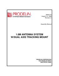
OverviewFEATUREEnvironmentalSpecifications subject to change without notice.TABLE 2-1 7200 ACS SPECIFICATIONSDESCRIPTIONAntenna Control Rack-mounted Unit:Temperature - 0°C to + 50°C; Humidity - 90% non-condensingDrive Cabinet:Temperature (Standard) -10°C to +50°CTemperature (Optional) -40°C to +50°C (Low temperature package)Humidity - 100% condensing.2.3 System ConfigurationRefer to Figure 2-1 for a typical overall block diagram of the integrated controlsystem. Items shown with solid interconnection lines represent fundamentalsystem components that provide automatic positioning for a two-axis system.Items connected with a dashed line represent typical system options such as atracking receiver, POL motorization components, Customer-Furnished Equipment(CFE), and remote Monitor and Control (M&C) equipment.Figure 2-1Typical 7200 ACS Block Diagram2-3
OverviewThe standard main input voltage for the drive cabinet is either 208 VAC threephaseWYE, or 380 - 415 VAC three-phase WYE requiring a four-wire circuit plus aground conductor. The actual current/power requirements for a given system areessentially established by the drive motor characteristics with only a small portionbeing used for control logic power. Other input voltages and frequencies areavailable as options, as is single-phase input power (the drive motors remain threephasein this case as the inverter modules perform the required conversion). Theinput power wiring connects to pressure-type lug terminals on the main circuitbreaker housing inside the drive cabinet.NOTE: In all cases, power wiring to the drive cabinetmust be sized for the rated currents and voltage drop and installedby qualified personnel in accordance with local codes.Power for each of the drive motors is supplied from the drive cabinet throughdouble insulated cables which are run through conduit and other enclosures servingas cable plenums and pull boxes. The motor power conductors connect topressure-type lugs on terminals in the drive cabinet and in the motor junctionboxes. Motor power wiring is sized for rated currents and voltage drops and isprotected by overcurrent devices as defined by the regulations of the NationalElectrical Code (NEC), International Electrotechnical Commission (IEC), andInstitute of Electrical and Electronic Engineers (IEEE).Overtravel limit switches for each axis are interfaced with the drive cabinet viadouble insulated control cabling. In the drive cabinet, drive interlock logic isprovided for each direction of travel and a summary limit alarm is developed andprovided to the ACU for display. The limit switch cables connect to pressure-typeterminals at each limit switch and in the drive cabinet.Axis drive commands and drive cabinet status signals are passed between the ACUand drive cabinet through a 25 conductor, #22 AWG cable with a maximum lengthof 1500 feet. The cable connects to a pressure-type terminal strip in the drivecabinet and terminates into a 25-pin female D-connector at the rear of the ACU.The AZ, EL, and POL (three-axis systems) and AZ, EL, POL and 4TH AXIS (fouraxissystems) transducers interface directly with the ACU via a shieldedmulticonductor cable for each device. The standard configuration includes singlespeed,brushless resolvers that require three twisted pair cables. The cablesterminate to flying leads at the resolver via solder or positive crimp connectionsand terminate into male D-connectors at the ACU end (25-pin for AZ and EL; 9-pinfor POL). Other types of position transducers, including high accuracy two-speedresolvers and absolute optical encoders, are available as options to accommodatecritical antenna pointing accuracy requirements or to provide additional resolutionfor narrow beamwidths.2-4
OverviewIn applications requiring closed-signal-loop tracking (Steptrack and OPT), a serialconnection between the <strong>General</strong> <strong>Dynamics</strong> DTR tracking receiver and the 7200ACU provides the ACU with the beacon signal level. Alternatively, an analogtracking signal is accepted through the ACU rear panel via J21 (a 9-pin D-connector). The nominal tracking voltage input is in the range of 0 to 10 VDC,with a slope of 0.2 V/decibels (dB) to 1.0 V/dB. Beacon select outputs areprovided on a 7200 ACU rear panel terminal strip (TB1), allowing remote manual orautomatic beacon selection with <strong>General</strong> <strong>Dynamics</strong> tracking receivers.Full function remote control of the tracking system is facilitated through the10BASE-T Ethernet port or one of the serial ports (both EIA/TIA-232E and EIA/TIA-422B are provided). An IEEE-488 (also known as GPIB), interface is also availableas a factory option.A summary alarm contact is provided on the ACU rear panel user interface terminalstrip TB1. The contact can be wired to a warning light, buzzer or M&C interface toalert the station operators that the 7200 ACU has a summary fault condition.2.4 System HardwareThe 7200 ACS consists of the following subsystems:• Model 7200 ACU• 7150 Drive cabinet• Position Feedback DevicesThe system interfaces with three-phase induction motors for AZ and EL positioningand a single-phase AC synchronous stepping motors for POL rotation. Limitinterfaces are for normally closed switches that open upon engagement.2-5
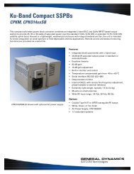
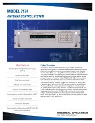
Overview2.4.1 7200 ACU HardwareThe Model 7200 ACU is a technically advanced, specially designed, multitaskingembedded control computer that includes input and output circuitry sufficient forinterfacing with all other related tracking system components. The ACU hardwareis based upon the industrial Versa Module Europe (VME64 (VITA 1-1994)) busarchitecture, providing extreme versatility and reliability far above many otherhardware platforms. Several printed circuit cards and peripheral subassemblies,described in subsequent sections, are integrated in a custom chassis to comprisethe ACU. The primary components of the 7200 ACU are:• Front Panel Display Assembly • Rear Panel PCB• Keyboard Controller PCB • One Power Supply• Digital I/O Daughter PCB • VCPU PCB• Optical Encoder PCB (Optional) • Single/Dual-Speed RDC PCB (Optional)• Optical Encoder I/O PCB (Optional)The 7200 ACU front panel is shown in Figure 2-2. The 7200 ACU functional blockdiagram is shown in Figure 2-3. Figures 2-4 and 2-5 show the top and side viewof the ACU respectively. (Refer to the engineering drawings in Section 7.0)Figure 2-27200 Antenna Control Unit Front Panel2-6
OverviewFigure 2-37200 ACU Functional Block Diagram2-7
OverviewFigure 2-47200 Antenna Control Unit Top ViewFigure 2-57200 Antenna Control Unit Side View2-8
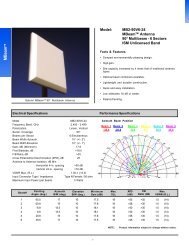
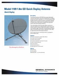
Overview2.4.1.1 VertexRSI Central Processing Unit (VCPU) PCB AssemblyThe 7200 ACU uses the Motorola 68030 32-bit microprocessor as the CentralProcessing Unit (CPU), providing sufficient computing power for the sophisticatedcontrol and tracking algorithms used by the ACU. A dedicated VME CPU circuitcard is provided, which includes the CPU, Read-Only Memory (ROM), RandomAccess Memory (RAM), bus control circuitry, and nonvolatile memory controlcircuitry, providing efficient and reliable system operation.The VCPU card has several indicators and switches mounted on the VME frontpanel to provide the user with basic diagnostic information.Figure 2-6VCPU CardD1 Halt LED – This bi-color green/red LED indicates the operational status of the68030 CPU. If this LED is red the processor is halted and the system will notoperate, consult the factory for assistance. This LED will always be illuminatedgreen even when the board is held in reset.D4 Reset LED – This bi-color green/red LED indicates the reset status of the board.If this LED is red it means the board is in reset. The following events can cause areset condition to occur:1) 2.5 VDC undervoltage fault – If this is the cause then LED D2 (SMT LEDlocated between the battery and the left hand side of the board) will beextinguished indicating that the 2.5V power supply source has fallen below2.38VDC. Check the voltage to ensure it is above 2.38VDC. Potentiometer PT1sets the threshold for this fault (Re-adjust per <strong>General</strong> <strong>Dynamics</strong> document <strong>CG</strong>-0283).2) 3.3 VDC undervoltage fault – If this is the cause the battery monitor IC (U1)has detected a voltage lower than 2.9 VDC. Check the 3.3V regulator output(VR1) to see if 3.3V is the output voltage.3) 5.0 VDC undervoltage fault – If this is the cause then LED D3 (SMT LEDlocated between the battery and the left hand side of the board) will beextinguished indicating that the 5.0V power supply source has fallen below4.75VDC. Check the voltage to ensure it is above 4.75VDC. PotentiometerPT2 sets the threshold for this fault (Re-adjust per <strong>General</strong> <strong>Dynamics</strong> document<strong>CG</strong>-0283).4) Dip Switch S6 pos 6 in the ON position – Leaving this dip switch in the ONposition holds the board in reset; change the position of the switch to the OFFposition to allow the board to operate normally.2-9
Overview5) Momentary Pushbutton switch S1 is pressed – This switch is spring loaded soit should not be able to remain pressed in (which will hold the board in reset);however, if it were to be held in place by something mechanically binding it,then the board would remain in reset; press the reset push button switch S1several times to ensuring that it is springing back out with each release.Reset Switch S1 - The momentary reset switch allows the user to reset the systemCPU. Resetting the board is similar to cycling the power on the unit except themain RAM bank of memory on the board is not erased (as it is when the power iscycled). This reset switch is mainly used by <strong>General</strong> <strong>Dynamics</strong> softwaredevelopment personnel but can also be used by site operators whentroubleshooting.Hex Rotary Switch S2 – This rotary switch is used to determine which firmware torun when the system is powered on. The VCPU contains enough flash memory tohold four unique versions of application code (each of these four allocations inmemory is referred to as a boot bank). This is useful when upgrading the 7200ACU firmware because the new image can be uploaded to another boot bank, therotary switch can be changed, and the ACU can be booted up with the newapplication firmware without erasing the original factory supplied application code.The rotary switch positions and their respective functions are defined in the tablebelow:TABLE 2-2 VCPU S2 HEX ROTARY SWITCH POSITIONS DEFINITIONS2 SWITCH POSITIONDESCRIPTION0 (Factory Setting) On power-up, run the application firmware contained in boot bank 0.1 On power-up, run the application firmware contained in boot bank 1.2 On power-up, run the application firmware contained in boot bank 2.3 On power-up, run the application firmware contained in boot bank 3.4 - D Unused (currently these positions are treated like position E).EFOn power-up, run the MONDO Monitor program. MONDO is a low level monitorprogram used by <strong>General</strong> <strong>Dynamics</strong> to power-up, test and program a new 7200ACU. MONDO uses an ASCII based protocol to interface with a PC via a terminalprogram via serial port 0 (front panel display or serial port 1 – J14 on the rear of the7200).On power-up, run the Swift X talker (Used by <strong>General</strong> <strong>Dynamics</strong> software developersonly)Hex Rotary Switch S3 – This rotary switch is used to determine which self-test theVCPU will run when powered up. The VCPU contains self test code which aredivided into three categories:1) Destructive Tests – These tests erase memory, which would cause the user tohave to reload the parameters and application code.2) Independent Tests – These tests can be run without the need for external testcables and other test hardware. The following circuits are functionally tested:floating point coprocessor, real time clock, serial ports (loopback internal to the2-10
OverviewUART), CPU interface to the Ethernet controller microcontroller, the rotaryswitches S2, S3 and the dip switch S4.3) Dependent Tests – These tests require special test jigs and are run by factorypersonnel to verify operation of the system.This self-test code is only run if DIP switch S4 pos 8 is in the ON position. Toprevent against “accidentally” running these tests, the tests are also interlockedwith the Keyboard controller card. If the keyboard controller card is detected, thetests will be aborted. The serial port between the keyboard controller card and thedisplay controller card should be unplugged to allow the tests to proceed.TABLE 2-3 VCPU S3 HEX ROTARY SWITCH POSITIONS DEFINITIONS3 SWITCH POSITION0 (Factory Setting) On power-up, no self-test code is run.DESCRIPTION1 On power-up, the destructive suite of tests is run.2 On power-up, the independent suite of tests is run.3 On power-up, the dependant suite of tests is run.4 - E Unused.FOn power-up, run all tests sequentially.DIP Switch S6 – This DIP switch directly controls various hardware related boardfunctions as defined in the following table:TABLE 2-4 VCPU S6 DIP SWITCH POSITIONS DEFINITIONS6 SWITCH POSITION OFF POSITION (SWITCH OPEN) ON POSITION (SWITCH CLOSED)1 - 4 Flash Write Disabled ♦♥ Flash Write Enabled5 EEPROM Write Disabled♦ EEPROM Write Enabled6 Normal Operation♦ Hold the VCPU board in Reset7 CPU Watchdog Disable♦ CPU Watchdog Enable8 Board Reset Disabled Board Reset Enabled♦♦ Denotes the normal operating position of the switch (factory setting).♥To program the flash boot banks with new application code, S6 pos 1-4 must be in the ON position; after programming iscomplete, return these four switches to the OFF position.DIP Switch S4 – This DIP switch controls various software functions as defined inthe following table.TABLE 2-5 VCPU S4 DIP SWITCH POSITIONS DEFINITIONS4 SWITCH POSITION OFF POSITION (SWITCH OPEN) ON POSITION (SWITCH CLOSED)1 Password Protection Enabled♦ Password Protection Disabled2-6 Unused♦ Unused7 Standard Boot Up ♦ Resets all params to factory defaults on Boot8 Self Test Mode Disabled♦ Self Test Mode Enabled♠♦ Denotes the normal operating position of the switch (factory setting).♠ Enabling self-test mode should ONLY be performed when directed to do so by <strong>General</strong> <strong>Dynamics</strong> technical support. Someof the self-tests erase NVRAM (parameter storage space) and some erase all the flash banks (application firmware).2-11
OverviewPotentiometer PT3 – The analog input circuit contains an AGC gain amplifier. Thegain of this amplifier is adjusted by PT3. To use the AGC gain amplifier, the shuntplug on 20<strong>13</strong>58-01 site J4 must be moved from the “Bypass” position (factorysetting) to the “Gain” position. Refer to the A/D Calibration section of <strong>General</strong><strong>Dynamics</strong> Document #<strong>CG</strong>-0283.2-12
OverviewPotentiometer PT4 – The analog input circuit contains a zero offset calibrationpotentiometer PT4. Refer to the A/D Calibration section of <strong>General</strong> <strong>Dynamics</strong>Document #<strong>CG</strong>-0283.Potentiometer PT5 – The analog input circuit contains a gain calibrationpotentiometer PT5. Refer to the A/D Calibration section of <strong>General</strong> <strong>Dynamics</strong>Document #<strong>CG</strong>-0283.Table 2-6 provides miscellaneous performance specifications that are inherent tothe VCPU board.TABLE 2-6 VCPU PERFORMANCE SPECIFICATIONSDescription Typical Calculated Worst CaseReal Time Clock Accuracy+0.26 to –0.42 Seconds/Day+/- 0.16 Seconds/Day(A TCXO drives this clock)(@ 0-50 Degrees C)NVRAM Battery Backup Shelf Life(external power source off)NVRAM Battery BackupNormal Operation (external powersource operational)Battery Change Period (withoutNVRAM corruption) *24 Months-15 Months(@ 0 Degrees C)>45 Seconds >21 Seconds90% capacity after 10 years due toself discharge(@ 25 Degrees C)* A capacitor keeps the NVRAM powered while the battery is being replaced. This row in the table defines the minimumamount of time that the discharging capacitor will keep the NVRAM powered without the battery present.2.4.1.2 User InterfaceOne of the most striking and advanced features of the 7200 ACU is the userinterface, which combines an 8-inch by 4-inch electroluminescent display with acustom 24-station keypad to provide the most straightforward, powerful, and userfriendlyoperating platform in the industry. As shown in Figure 2-2, the 7200 ACUfront panel layout is uncluttered and offers a logical format for the display ofinformation. For more information on the user interface refer to Section 2.5.1.2.4.1.3 Digital Input/Output Printed-Circuit Board AssemblyThe I/O PCB provides the electrical interface between the ACU and the drivecabinet. In addition, the I/O card serves as the interface between the CPU and theACU rear panel status inputs and control outputs. There are a total of 24 digitalinputs (some inputs are used internally so all 24 are not available through the rearpanel connectors). See table 2-7 for the digital inputs specifications.2-<strong>13</strong>
OverviewTABLE 2-7 7200 DIGITAL I/O SPECIFICATIONSVoltage LevelsInput ImpedanceDIGITAL INPUTSTransient Voltage SuppressionDIGITAL OUTPUTSCONNECTOR TB1 ONLYOutput TypeMaximum Input VoltageMaximum Load CurrentDESCRIPTIONLogic Level High Voltage Range: (+4.5 to +26.7 VDC)Logic Level Low Voltage Range: (0 to +1 VDC)10 K Ohms (Nominal)Electrostatic discharge (ESD) as defined in IEC 1000-4-2,Electrical fast transients (EFT) per IEC 1000-4-4DESCRIPTIONRelay Contact Closure220 VDC or 125 VAC RMS1 AmpMaximum Switched PowerDIGITAL I/OCONNECTORS J10 & J11Output TypeMaximum Input Voltage62.5 VAOpen Collector Transistor26.7 VDCDESCRIPTIONMaximum Load Current500 mAElectrostatic discharge (ESD) as defined in IEC 1000-4-2,Transient Voltage SuppressionElectrical fast transients (EFT) per IEC 1000-4-4Specifications subject to change without notice.2.4.1.4 Resolver-to-Digital Converter Printed-Circuit Board AssemblyThe Resolver-to-Digital Converter (RDC) PCB accepts analog inputs from theantenna-mounted AZ, EL, and/or POL resolvers (via the rear panel terminationcircuit card) and provides a binary digital encoded representation of the pointingangles for each axis to the CPU. VME bus interface circuitry is included, basedupon CPU and RDC timing requirements. The standard configuration is for singlespeedresolvers and 16-bit encoding; however, the RDC PCB can be configured toaccept dual-speed resolver inputs and provide higher resolution as required.Alternate means of position encoding are available, including high accuracyabsolute optical encoders, in which case an alternate position interface circuit cardis provided.2.4.1.5 Optical Encoder Daughter Board (Optional - AZ and EL)The OE daughter card is mounted on its own VME card. This card takes the EIA-422A serial encoder data and converts it to 24 bits for use by the CPU. TwoComplex Programmable Logic Devices (CPLDs) are employed to convert the bufferedserial data to parallel data for use by the CPU. The card reads each encoder about4000 times per second. The bits of position resolution are dependant on the actualoptical encoder used, however, most optical encoder systems have 18 bits ofresolution.2-14
Overview2.4.1.6 Dual Channel Resolver-to-Digital Converter PCB Assembly(Optional POL and 4TH AXIS)The Resolver-to-Digital Converter (RDC) PCB accepts analog inputs from theantenna-mounted resolvers (via the rear panel termination circuit card) and providesa binary digital encoded representation of the pointing angles for the POL and 4THAXIS to the CPU. VME bus interface circuitry is included, based upon CPU andRDC timing requirements. The standard configuration is for single-speed resolversand 16-bit encoding.2.4.1.7 IEEE-488 Interface (Optional)The IEEE-488 bus has been optionally incorporated into the 7200 ACU toaccommodate users wishing to utilize this type of interface. The IEEE-488 busallows connectivity between different programmable devices with a standardinterface for communications between each instrument. The IEEE-488 interface isalso known as GPIB (<strong>General</strong> Purpose Interface Bus) or HPIB (Hewlett PackardInterface Bus), and is electrically similar to IEC-625. Please refer to document <strong>CG</strong>-6041 for M&C protocol for this interface.2.4.1.8 Time and Frequency Processor Board (Optional)The 7200 ACU clock accuracy can be precisely maintained by utilizing the optionalTime and Frequency Processor Board. This VME board is used in conjunction withan external (CFE) time source to synchronize the 7200 ACU clock to the accuratetime source. The external time source sends an IRIG-B compliant signal to the J3BNC connector on the rear of the 7200 ACU. This signal is routed to the Time andFrequency Processor Board (TFP). The VCPU board acquires only the year fromthe on-board real-time clock while the rest of the time/date information is takendirectly from the TFP board. If the TFP board becomes disconnected from itssource, a message will be displayed on the ACU “External Timing Source Lost”.2.4.1.9 ACU Chassis AssemblyThe ACU is housed in a custom chassis assembly which mounts in a standard 19-inch Electronics Industry Association (EIA) rack, requiring 7-inches of vertical rackspace (4 Rack Units per EIA 310). The nominal overall dimensions of the ACUchassis are: 7-inches tall by 19-inches wide by 20-inches deep. The 7200 ACU’sweight is approximately 27 lbs. A four-slot VME card cage, which houses theVCPU, I/O, and RDC PCB’s, is mounted to the inside of the chassis top plate. Thetop plate is hinged at the rear of the chassis and includes a locking support arm tofacilitate convenient front-side access to the card cage. Studs connected to thefront panel support the front panel display and keypad and their respective controlcircuit cards.2-15
OverviewA VME backpanel PCB serves as the bus interface and DC power supplydistribution system for the CPU and RDC PCB’s. Two of the four slots are availablefor future expansion and/or customized features and factory options.A PCB mounted to the ACU rear panel accepts all external wiring and connectors(with the exception of the line cord) and serves as a “break-out” device withconnections to each of the circuit boards in the card cage.Two cooling fans are provided to ensure operation of the ACU internal componentsremain well within device ratings. The fans are powered from the +24 V output ofthe power supply.2.4.1.10 Power Supply, EMI Filter and FusePower for all ACU components is provided by one power supply assembly, whichis mounted to the bottom plate of the chassis. This power supply is a quadoutput, switched mode type, providing output voltages of +5, ±12 and +24 VDCfor all logic and control circuits. Nominal power requirements for the ACU are 75VA at 100 to 240 VAC, 50 or 60 Hertz (Hz).The power supply used in the 7200 ACU has an automatic shutdown feature incase over-current conditions occur. The system also has a line fuse on the rearpower entry module in case of a ground fault. An input line-conditioning filterprovides Electromagnetic Interference (EMI) suppression.AC POWER INPUTInput Voltage RangeInput Power RequirementsInput Surge CurrentInput Power FactorInput Frequency RangeFuse Current RatingTABLE 2-8 7200 POWER INPUT SPECIFICATIONS100 to 240 VAC Nominal75 VA Typical25 Amps Max. @ 25 degrees CDESCRIPTION0.98 Typical (Active Power Factor Corrected Supply)50 to 60 Hz Nominal (47-63 Hz Max.)2 AmpsFuse Type 5 x 20 mm Time Lag Fuse (Slo-Blo Type Fuse) per IEC 60127-2 Sheet 3Specifications subject to change without notice.2.4.2 Antenna Drive Cabinet HardwareThe standard motor drive cabinet is a freestanding, foot-mounted aluminum NEMA-4X enclosure with overall dimensions of approximately 36-inches tall by 30-incheswide by 10-inches deep (91.4 cm tall by 76.2 cm wide by 25.4 cm deep). Thealuminum cabinet provides outstanding corrosion protection even in the harshest ofenvironments. The cabinet weighs approximately 150 lbs. (68 kg) and isoperational in altitudes of up to 10,000 ft. (3,048 m). The input power to thecabinet can vary according to the particular drive cabinet that was ordered withyour system; please see the specific system documentation for more information.2-16
OverviewA functional block diagram of the drive cabinet is shown in Figure 2-7.Figure 2-7Drive Cabinet Block DiagramThe drive cabinet consists of the following major components:• Portable Maintenance Control Unit• Main and Inverter Drive Circuit Breakers• EMERGENCY STOP SWITCH• AZ Variable Speed AC Drive Unit (Inverter)• EL Variable Speed AC Drive Unit (Inverter)• 24 VDC Power Supply• Control Circuitry for the POL Motors (In Three-Axis and Four-Axis Systems)Figure 2-8 shows the major components of the drive cabinet. Refer to theengineering drawings in Section 7.0.2-17
OverviewGPD 315 GPD 315Figure 2-8Drive Cabinet AssemblyThe Portable Maintenance Control Unit (PMCU) located inside the 7150 DriveCabinet allows the operator to control antenna movement from the proximity ofthe antenna.The MAIN CIRCUIT BREAKER controls the main power to the drive motors, thelimit switches, and the drive cabinet, but does not provide power to the 7200ACU. Each inverter has an individual circuit breaker for protection. This circuitbreaker will cut off mains power to the cabinet, but mains power can also beinstalled in such a way that it can be cut off external to the cabinet if necessary.The EMERGENCY STOP switch (on the outside of the drive cabinet), whenpressed, removes power from the drive motors by opening the drive enablecontactor.The AZ and EL inverters provide pulse-width-modulated motor current, allowingcontinuously variable drive rates over a range of up to 50 to 1.The 24 VDC power supply provides operating voltage to the drive cabinet relaycircuit board.Relay PCB accepts all limit switch status inputs and controls the commands to theinverter drives and the POL motors.2-18
Overview2.4.2.1 AZ and EL Drive InvertersOne of the critical advantages of the 7200 ACS over many other systems is theuse of variable frequency drive inverters to control the speed of standard threephaseinduction motors for AZ and EL antenna motion. This approach has severaldistinct advantages over the commonly used and simplistic on/off contactor controlof motor power. First, inverters allow <strong>General</strong> <strong>Dynamics</strong> to offer two-speedcontrol in a standard configuration without the problems associated with specialdual-wound motors or clumsy clutching arrangements. Secondly, the invertersoffer precision motor control by ramping motor speeds up and down in a controlledmanner rather than simply switching full motor power on and off and having tocontend with inertial coasting of the motor rotor and the related axis overshoot. Inaddition to these two distinct advantages, the inverter drives offer superior motorprotection through sophisticated electronic motor overcurrent protection. Motorcurrent is continuously monitored and compared against allowable levels fordifferent conditions. Should the actual measured current exceed the allowablelevels, the inverter trips and the drive is disabled. The inverter then has thecapability to automatically reset and continue operation, provided the currentremains within allowable limits.2.4.2.2 Polarization Motor Control (POL and 4th Axis)A three-axis system uses a single-speed AC synchronous stepping motor for feedassembly rotation (POL). In the four-axis system a pair of single-speed ACsynchronous stepping motors are used for feed assembly rotation. Both POLmotors are controlled and powered from the 7150 drive cabinet. Drive power tothe POL motor(s) is switched, according to the required direction of rotation, byrelays located on the Relay PCB. A resistance-capacitance (RC) network in thedrive cabinet provides the proper phase relationship to each motor.2.4.2.3 Drive Cabinet Control LogicMotor drive commands and interlock functions in the drive cabinet are performedwith relay logic operating at +24 VDC, which is derived from a regulated powersupply. Commands can be received from the ACU, or PMCU, for motor speed anddirection. The Drive Reset is controlled from the Relay PC board and theEmergency Stop is located on the right side of the enclosure. The drive cabinetrelay logic then commands the axis drives accordingly. Likewise, limit switchesmounted on the structure activate relays in the drive cabinet upon engagement toform axis interlocks and provide the appropriate fault reporting to the ACU.2-19
Overview2.4.2.4 Local ControlLocal (Maintenance) control of the antenna drives is facilitated through a set ofswitches on the PMCU in the drive cabinet. A MAINT/REMOTE switch located onthe Relay PCB allows the operator to select between ACU control and local drivecabinet control. With the select switch set to the MAINT position, ACU control isdisabled; however, all status reporting remains fully operational at the ACU.2.4.2.5 Drive Cabinet Overcurrent ProtectionAs described in Section 2.4.2.1, "intelligent" electronic overcurrent protection isprovided for AZ and EL drive motors by the variable frequency inverters. Inaddition, there are several other protection devices integral to the drive cabinet.The inverter inputs are individually protected by circuit breakers, offering shortcircuitprotection in the event of a drive inverter catastrophic failure. The +24VDC logic power supply has a line input circuit breaker for short circuit protection.In three-axis and four-axis systems, the POL motor circuit(s) is individuallyprotected by a circuit breaker. A main input power circuit breaker is also provided,which serves as an internal disconnect for the entire cabinet.2.4.2.6 AZ and EL Drive MotorsThree-phase induction gearmotor assemblies are utilized for actuation of the AZand EL axes. The motors are sized based upon deadweight, frictional, and windloadingrequirements, as well as the required axis velocities. The standard motorscan be connected for either 208 or 380 - 415 VAC three-phase input, based uponthe line voltage available to the drive cabinet. The motors have sealed, permanent,synthetic grease lubricated bearings and the gearboxes are lubricated withsynthetic gear oil, minimizing maintenance requirements.2.4.2.7 Absolute Position TransducersAngular position feedback is provided by absolute position transducers (resolvers)for each axis. The standard configuration includes size 11 single-speed, brushlessresolvers which, combined with the position encoding circuitry in the ACU, yield anaccuracy of 0.02 degrees, root mean square (RMS). The resolver reference voltagefor the standard devices is 4.6 V RMS, at 2500 Hz.Encoding system options include electrically wound two-speed resolvers orabsolute optical encoders to provide increased resolution and accuracy. With thetwo-speed option, an overall control system accuracy of 0.01-degree peak error isachieved. In this configuration, dual monolithic resolver-to-digital conversion IC'sare used in the ACU with bit rotation techniques incorporated to significantlyincrease binary resolution. Various optical encoder configurations allow forresolution and accuracy levels commensurate with the most demanding systemapplications.2-20
Overview2.4.2.8 Axis Overtravel Limit SwitchesOvertravel is prevented in each direction for each axis of rotation by electrical limitswitches with normally closed (open upon limit engagement) contacts. Theswitches are designed with double break contacts such that movement of theswitch actuator in either direction opens a corresponding set of discrete contacts.In this manner, only one limit switch assembly is required for each axis. Eachswitch is mounted with brackets, including adjustable strikers for each direction oftravel.2.4.2.9 Drive Cabinet Low-Temperature OptionThe standard 7200 ACS drive cabinet is rated to operate in an outside ambienttemperature range of 14° F (-10 °C) to 122° F (+50 °C). For systems where theambient temperature will fall below 14° F (-10 °C), an optional low-temperaturepackage is available for the drive cabinet.For the low-temperature option package, a 200 watt forced air convection heaterwith integrated fan and wall insulation are installed inside the drive cabinet. Overcurrent protection is provided by an individual circuit breaker sized to the wattageand input voltage of the heater. When the thermostat inside the drive cabinetregisters a temperature below 41°F (5°C), the heater is activated and heats the airinside the drive cabinet. An external thermostat shuts the heater off when outsideair exceeds 41°F (5°C). The heated air maintains the internal temperature of thedrive cabinet to within the standard operating temperature range.2.5 Controls and IndicatorsThe controls and indicators for the 7200 ACS are located on the ACU and insidethe drive cabinet. The EMERGENCY STOP button is located on the outside of thedrive cabinet and additional optional emergency stop switches may be provided atother locations.2.5.1 7200 ACU Controls and IndicatorsThe controls and indicators for the ACU are located on the front panel and on therear panel. The following sections describe the functions of the ACU controls andindicators.2.5.1.1 The Power On/Off SwitchThe power on/off switch is located on the rear of the 7200 ACU in the powerentry module. When the switch is set to the on position, power is applied to thepower supply in the ACU.2-21
Overview2.5.1.2 The Alphanumeric DisplayThe 7200 ACU user interface combines an 8-inch by 4-inch electroluminescentdisplay with a custom 24-station keypad to provide the most straightforward,powerful, and user-friendly operating platform in the industry. Figure 2-8 showseach section of the 7200 ACU display, and each section is described in detail inthe following sections.System ControlPointTracking SignalStatus & LevelTimeName andCurrent PositionCurrent TargetMode StatusFault StatusMode SelectionConfigurationEditingHelp MessagesFigure 2-97200 Antenna Control Unit DisplayThe display is divided into upper and lower sections: the upper section (approximately60 percent) is dedicated to real-time information display, and the lower section isused for interactive mode selection, configuration, editing, and help messages. In thereal-time display section, "current pos" AZ and EL angles are displayed in double-sizecharacters. A user-configurable alphanumeric field to the left of the current positionangles allows for labeling (naming) the display, primarily to aid identification inmultiple-antenna stations. The line of information directly below the current positioninformation (also double-size characters) identifies the target currently being accessedby the system. If the system is in the process of moving from one target to another,or in a program tracking mode of operation, the target (or next position) angles arealso displayed directly below the current position angles.Immediately below the target name field is a line of information that displays thecurrent mode of operation and pending modes. The current target shown in Figure 2-9 is “A” and the mode status line shows that the current tracking mode is OPT.Shown at the top of the display are current time (Coordinated Universal Time (UTC)and/or local), user level (Monitor, Operator, or Supervisor) and tracking signal sourceand level. Each of these items may be blanked out by the user if not required in aparticular application (refer to Section 5.8.6.14 for information on user interfaceoptions).2-22
OverviewSystem fault status is reported in inverse, double-size characters in the field belowthe Tracking mode status line. In the event of multiple fault conditions, the faultmessages are scrolled continuously at approximately one-second intervals. An audiblealarm (if the alarm option is turned on) accompanies any major fault and may besilenced from the front panel keypad (refer to Section 5.8.6.14 for information onuser interface options). To the right of “UTC”, an asterisk “*” will appear if anoptional time and frequency processor board (IRIG-B) is installed and has locked ontoan external signal at least once (refer to Section 2.4.1.8).The lower portion of the display allows fully menu-driven selection of control modes,parameter editing, etc. A logical tree structure provides for easy and efficient systemoperation with minimal reliance upon system operation manuals. One item in eachmenu is always highlighted by an inverse-video cursor, which is controlled by keypaddirection keys. The [ENTER] key then selects the highlighted item either for activationor editing. A dedicated [HELP] key and context-sensitive help messages serve toremind the operator of operational functions.The display control PCB receives commands from the CPU through a serial link andprovides appropriate decoding and driver functions for illumination of the display.2.5.1.3 The KeypadCommands from the keypad are decoded and serialized through a dedicated keypadcontrol PCB and sent to the CPU through a serial link shared with the display controlserial link. A speaker located on the keypad control circuit board provides an audiblealarm for fault conditions. Refer to Table 2-9 for explanations of the function of eachkey.2-23
OverviewTABLE 2-9 7200 ACU KEYPAD CONTROLSCONTROL↑↓→←PG DNPG UPENTERPRIORMAINSTOPRESUMEHELPSHIFT+/-YES/NOA/B•EXPFUNCTIONMoves the selection cursor up. In one-screen menus, the up arrow moves the cursor from the bottomitem in the right column to the top of the left column, but does not wrap from the top of the leftcolumn to the bottom of the right column. In menus filling more than one screen, it will return toprevious screens. Also used to toggle between preprogrammed choices for tracking modes, namingtargets, etc. (refer to Section 5.0 of this manual).Moves the selection cursor down. In one-screen menus, the down arrow moves the cursor from thetop item in the left column of a menu to the bottom of the right column one item at a time, but doesnot wrap from the bottom of the right column to the top of preceding left column. In menus fillingmore than one screen, the down arrow will reveal additional screens of information when it is pressedfrom the bottom right position. Also used to toggle between preprogrammed choices for trackingmodes, naming targets, etc. (refer to Section 5.0 of this manual).Moves the selection cursor to the right. In one-screen menus, the right arrow moves the selectioncursor from the left column to the right column, but does not wrap the selection cursor from the rightcolumn to the left column. In multi-screen menus, it will reveal additional screens of information.Moves the selection cursor to the left. In one-screen menus, the left arrow moves the selectioncursor from the right column to the left column, but does not wrap the selection cursor from the leftcolumn to the right column. In multi-screen menus, it will return to previous screens of information.When pressed simultaneously with [SHIFT] key, changes display to the next page for multiscreenmenus. Has no effect on single-screen menus.When pressed simultaneously with [SHIFT] key, changes display to the previous page for multiscreenmenus. Has no effect on single-screen menus.Selects the currently highlighted item.Returns to the last screen viewed before the user pressed [ENTER] or [HELP]. During in-line editing,restores data to the value it had before [ENTER] was last pressed.When pressed simultaneously with the [SHIFT] key, returns to the Main menu.[MAIN] key is pressed while editing data, all changes that have been made are lost.NOTE: If theStops movement of the antenna when pressed. Keyboard Stop flashes on the screen in double-sizeletters. If the audible alarm is turned on, the alarm sounds until the [SHIFT] and [RESUME] keys aresimultaneously pressed (or Clear/correct system faults is selected).When pressed simultaneously with the [SHIFT] key, resumes tracking when a tracking mode isinterrupted by keyboard stop.Provides access to the context sensitive help screens from anywhere in the menu system.Allows the use of the shift functions shown in white letters on the keypad.Used when entering numerical parameters if the range includes negative numbers. Also used totoggle between Momentary and Sticky keypad mode for the ACU keypad.Toggles between YES and NO when setting parameters or when changing operating modes for thesystem.Toggles the display between POL only, 4TH AXIS only, and POL and 4TH AXIS (In Four-axis systemsonly)The period is used to enter floating-point numbers or to choose between POL and 4TH AXIS in fouraxissystems.Used for entering exponents into numeric data fields.In Manual antenna control mode, moves POL clockwise (CW). Has no other use.In Manual antenna control mode, moves POL counterclockwise (CCW). Has no other use.0 - 9The numeric keys are used for entering numerical data. Hexadecimal digits A - F may be entered bypressing the [SHIFT] key and 0 - 5, respectively.2-24
Overview2.5.1.4 Drive Enable SwitchWhen the DRIVE ENABLE switch is in the out position, it is illuminated, and the drivemotors are enabled through the drive enable contactor. When the DRIVE ENABLEswitch is engaged, and not illuminated, the drive motors are disabled, and a messageis displayed on the screen of the 7200 ACU.2.5.2 Drive Cabinet Controls and IndicatorsThe drive cabinet contains the following controls and indicators located on the PMCUand the Relay PCB. The function of each control is described in Table 2-10.CONTROLMAINT/REMOTEAZIMUTH SPEEDADJUSTAZIMUTH CW & CCWSWITCHELEVATION SPEEDADJUSTELEVATION UP & DNSWITCHCONTROL POWERCIRCUIT BREAKERCONTROL POWERLEDMAIN CIRCUITBREAKERDRIVE(S) CIRCUITBREAKERRECEPTACLECIRCUIT BREAKER(if installed)TABLE 2-10 DRIVE CABINET PMCU AND RELAY PCB CONTROLSFUNCTIONThe MAINT/REMOTE switch is located on the Relay PCB. When set to the REMOTEposition, transfers control to the 7200 ACU. When set to MAINT> the PMCU has controlof the system. The remote mode is selected when the switch is in the UP position.Maintenance mode is selected when the switch is in the DOWN position.Located on the PMCU. SLEW SPEED/TRACKING SPEED select switch - Selects the AZdrive speed (functional in MAINT mode only). SLEW SPEED - This speed is programmed into the AZ drive and sets the AZ high-speed drive rate. TRACKING SPEED - This speed isprogrammed in to the AZ drive and sets the AZ low speed drive rate.Located on the PMCU, when this switch is turned to CW and held it rotates the Azimuthin the CW direction at the speed determined by the AZIMUTH SPEED ADJUST Switchuntil the switch is released. When the switch is released it returns to center and themotion ceases. This switch when turned to CCW and held rotates the Azimuth in theCCW direction at the speed determined by the AZIMUTH SPEED ADJUST Switch untilthe switch is released. When released the switch returns to center and the motionceases.Located on the PMCU. SLEW SPEED/TRACKING SPEED select switch - Selects the ELdrive speed (functional in MAINT mode only). SLEW SPEED - This speed is programmedin to the EL drive and sets the EL high-speed drive rate. TRACKING SPEED - This speed isprogrammed in to the EL drive and sets the EL low speed drive rate.Located on the PMCU. This switch when turned to UP and held rotates the Elevation inthe UP direction at the speed determined by the AZIMUTH SPEED ADJUST Switch untilthe switch is released. When the switch is released it returns to center and the motionceases. This switch when turned to DN and held rotates the Elevation in the DN directionat the speed determined by the AZIMUTH SPEED ADJUST Switch until the switch isreleased. When released the switch returns to center and the motion ceases.Provides circuit protection for the DC power supply that provides 24 VDC for controlcircuits.The Light-Emitting Diode (LED) is located on the Relay PCB and illuminates green whenpower is ON.Provides circuit protection for entire drive cabinet power circuits.Provides individual circuit protection for each drive.Provides circuit protection for the duplex utility outlet on the leg of the drive cabinet.2-25
Overview2.6 System FunctionsThe 7200 ACS offers a full complement of standard antenna position control modesas well as a number of advanced tracking modes. For automatic tracking, the 7200ACS incorporates a new approach to control system operation with a unique targetorientedenvironment, which provides for the establishment of unique systemcharacteristics for multiple targets (satellites). In this manner, each target to beaccessed is user-configured with tracking mode, tracking signal frequency and slope,etc. A target-specific data base is established for any predictive or programmedtracking data relative to the target. Once configured, tracking for a target is initiatedand maintained in a fully automatic manner simply by invoking the "name" of thetarget. This greatly enhances normal operation of the system by reducing the levelof required operator expertise and intervention.Configuring a target includes the establishment of an operational mode to be used foraccessing that target. The following sections describe the available control modesfor the system in some detail. It should be noted that configuration of a new targetor editing of an existing target configuration is a relatively simple matter, with theACU user interface presenting information in logical order. As a result, the systemessentially allows for direct mode entry with the target configuration beingaccomplished in real time. For more information on configuring targets, refer toSection 5.8.2.6.2.7 StandbyIn Standby mode, the ACU does not command the antenna to move in any axis. TheAZ and EL inverters are powered-up but are not enabled, and brakes are set onsystems equipped with brakes. Real-time status, time, signal level, and positioninformation is being displayed on the ACU front panel along with any current faultinformation. In Standby mode, the ACU is in an active wait state for instructionsfrom the front panel or computer interface.2-26
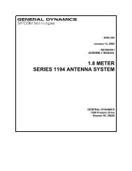
Overview2.8 Manual Control Via Portable Maintenance Control Unit(PMCU)Manual control of antenna position is provided from the drive cabinet PMCU or theACU user interface. Figure 2-10 shows the PMCU without and with the optionaldisplay.Figure 2-10Portable Maintenance Control Units2-27
Overview2.8.1 Manual Antenna Control from the Drive CabinetManual control of each axis is provided at the drive cabinet using the PMCU,primarily to facilitate antenna maintenance. Setting the MAINT/REMOTE switchlocated on the Relay PCB panel to MAINT mode transfers control of the system tothe PMCU, allowing maintenance to be performed on the system.Therefore, with this switch in the MAINT position, the ACU cannot assume control.With the switch in the REMOTE position, the ACU has control of the system and thePMCU is inoperative.2.8.2 Manual Antenna Control from the Antenna Control UnitReal-time manual jog control is provided at the ACU by dedicated keys on the keypad(one key for each direction of travel), which are activated by selecting Manualantenna control from the ACU Tracking Functions menu (refer to Section 5.8.2.5).For the AZ and EL axes, pressing the jog keys results in corresponding low-speedmotion of the antenna. Pressing the jog keys while pressing the [SHIFT] key resultsin high-speed antenna motion. POL jog control (3-axis systems) is single-speed only.4TH AXIS jog control (optional 4-axis systems) is also single-speed.2.9 Immediate TrackingImmediate tracking is the quickest method to begin tracking. Since it requires verylittle configuration, this method of tracking is useful for testing and moving theantenna to seldom used locations. The 7200 ACU provides immediate trackingmodes as described in the following sections. These tracking modes are accessedfrom the Main menu by selecting Tracking functions..., Immediate tracking…. Formore information on these tracking modes, refer to Section 5.8.2.4.2.9.1 Move to LongitudeThis mode is identical to Move to look angles, except that the user enters a longitudeon the geostationary arc instead of AZ and EL coordinates. The ACU computes theAZ and EL coordinates from the given longitude. (Refer to Section 5.8.2.6.3.4.)2.9.2 Move to Look AnglesIn this mode of operation, the system moves the antenna to a preprogrammed set ofAZ, EL, and POL(s) coordinates (look angles), then actively maintains the antenna atthat position. During the operation, the antenna is moved at slew (fast) speed untilrelatively close to the target, and then automatically switches to track (slow) speedfor precise positioning. Positioning is complete when the axis position feedbackreflects antenna positioning to within a user-definable deadband around the targetangles. (Refer to Section 5.8.2.6.3.5.)2-28
Overview2.9.3 SteptrackSteptrack mode provides automatic periodic positioning of the antenna for maximumreceive signal strength as measured at the ACU tracking signal input. The 7200 ACUutilizes the <strong>General</strong> <strong>Dynamics</strong> Adaptive Steptrack (AST) algorithm to perform thefunction of conventional steptrack peak signal optimization, eliminating the random"guessing" errors associated with predetermined fixed scan patterns. AST employsalternate AZ and EL peaking operations based upon a mathematical relationshipbetween the changes in receive signal level and angular antenna position. For eachaxis, an initial fixed-size step is taken; signal strength levels before and after the stepare used to determine the magnitude and direction of the corrective (peaking) steprequired. Once the peak position is determined, flags are set, indicating the directionof travel of the satellite so that the initial step for the next peaking operation will tendto move the antenna along the satellite ephemeris. This feature greatly reduces theerrors introduced by the "wrong" guess made during significant portions of the dailysatellite drift by algorithms that consistently make initial steps in a given direction.Steptrack peaking operations are performed at user-definable time intervals, or whenthe receive signal level falls below a user-settable threshold. Steptracking parameters,including tracking signal frequency, cycle time, track threshold, etc., are establishedfor each target, allowing maximum versatility for the system. (Refer to Section5.8.2.4.1)2.9.4 Star TrackingAutomatic Star tracking is provided as an aid in performing antenna gain calculationsby the radio star method. Such measurements require consistent, accuratepositioning along the path of a star with relatively high velocity. This can be done bymanual positioning, but automatic pointing yields more accurate tests, performed inless time. Based upon site location coordinates, automatic pointing for stars includingCassiopeia A, Taurus, and Orion is supported.2.9.5 Intelsat 11-element TrackIn this IESS-412 mode, the antenna is moved according to pointing data generatedusing the Intelsat Eleven Parameter Model. The ACU accepts element sets asdistributed by Intelsat, as well as local site data, and calculates the correspondingpredicted AZ and EL positions along the ephemeris. The antenna is then moved tothe predicted positions with sufficient frequency to maintain pointing within a userselectabledeadband around the theoretical values. The data for a given target ismaintained in a dedicated database for that target and is continually updated toprovide appropriate positioning anytime the target is accessed (within time of validityconstraints).2-29
Overview2.9.6 Orbital Element Track (Optional)The Orbital Element Tracking (OET) mode allows the user to input a Cartesian orbitalelement set to be used in an open loop pointing of the antenna over time. Thistracking mode is available as a target and can be set up from the front panel or theM&C interface. To use the OET mode the operator first creates an OET target byinputting Cartesian orbital elements at a specific epoch in the True Earth MeanEquinox (TEME) reference system. This element set has the general format ofDate/Time, X position, Y position, and Z position, X velocity, Y velocity and Zvelocity.Built in sanity checking is available in the form of expected means with acceptabletolerances. The user can enable or disable individually checks on the followingcharacteristics: Semi-major axis, Eccentricity, Inclination, Right Ascension of theascending node, and Argument of Perigee. If the input orbital elements differ fromthe enabled check by more than a preset tolerance, an error is issued and the orbitalelement set is not used.When the tracking mode is executed the ACU uses built in propagators and the realtime clock to calculate look angles for antenna pointing in real time. Two built inpropagators are available in the 7200 series controllers. The first is a two-bodypropagator based on Keplarian motion. The second is a multi-body propagator thatincludes the effects of Moon and Sun gravitational forces and a 4x4 Geopotentialmodel. The system uses the Two-Body for all start up look angle calculations andswitches to the Multi-Body when the element set has been brought up to real time.New look angles can be calculated as frequently as every ½ second out to every 120seconds.For proper operation of the OET mode it is important that the site information storedin the ACU be as accurate as possible. This means it should be acquired from sitesurvey information or averaged from a GPS receiver. The built in clock must be set toUTC time and updated once each day. Note: The internal real time clock can only beset to the second and at worst case could drift 1 second per day. The ACU read outsshould be carefully calibrated to the local azimuth/elevation reference system. Thefrequency at which new element sets should be input to the ACU will depend greatlyon the type of orbit represented. At minimum new elements must be provided eachtime a satellite maneuver takes place. The propagators will also deviate from real lifeover a period of time. This could be days, weeks or months depending on the orbit inquestion.2-30
Overview2.10 Tracking FunctionsThe 7200 ACU allows a user to configure up to 50 targets for establishment oftarget-specific databases (refer to Section 5.8.2.6). The following tracking modesare available:• Move to longitude (refer to Section 2.9.1)• Move to look angles (refer to Section 2.9.2)• Orbit Prediction Tracking (OPT)• Star tracking (refer to Section 2.9.4)• Intelsat 11-element (IESS-412) (refer to Section 2.9.5)• Orbital Element Track (Optional) (refer to Section 2.9.6)2.10.1 Orbit Prediction TrackingThe OPT system provides exceptional short-term and long-term pointing capabilitiesby combining orbital mechanics with modern modeling and error analysis techniques.Orbital mechanics are used to provide a model of the satellite and earth's surfacemotion. The modeling and error analysis takes pointing data collected in Steptrackoperations and finds the satellite orbital parameters and systematic errors caused bythe mechanical structure which provide the best least squares solution. The orbitalparameters and systematic errors are then fed back through the orbital mechanicsmodels to determine antenna look angles at any future point in time. The modelsaccurately match the "real world" and provide excellent real world results. (Refer toSection 3.1).2-31
Theory3.0 THEORYThis section provides in-depth information on OPT and Orbit scan, two of the moreadvanced features of the 7200 ACS.3.1 OPT3.1.1 Orbit PredictionOPT is the algorithm used by the 7200 ACS to predict the position of a spacecraftbased upon its previous motion. The basic principle proposes that if thespacecraft's position, velocity, and the forces acting upon it are known, itsposition can be predicted at any time in the future.An "OPT model" is what is referred to in orbital mechanics as an orbital elementset. An orbital element set describes the position and velocity of an orbiting bodyat some particular time (the epoch time, or simply, the epoch). OPT's positionpredictions are made by taking the orbital element set and using the data itprovides, along with the computed forces acting on the spacecraft, to predict theposition of the spacecraft at the desired time.The prediction is performed using an algorithm called a propagator. A propagatortakes an orbital element set at some epoch and produces an orbital element set ata later epoch. OPT uses two different propagators in its operations:• Two-body propagator: where only the earth's force on the spacecraft isconsidered and earth is modeled as a sphere with uniform mass.• Multibody propagator: where the following effects on the spacecraft areconsidered:- Earth's gravity, including a geopotential model (accounting for thenonuniformity of the earth's gravitational field).- Sun's gravity.- Moon's gravity.- Solar radiation pressure on the spacecraft.The two-body propagator is the simplest and fastest, and provides quick solutionswhile accounting for the most significant factor affecting the spacecraft's motion.The more complex multibody propagator provides a more accurate model of thespacecraft's actual motion.3-1
Theory3.1.2 Orbit DeterminationAn orbital element set is composed by making an initial guess of the orbit and thengenerating positions from this guess using the propagators described previously.These positions are compared with the positions gathered by AST. The differencesbetween AST data and propagator-generated data are used to determine acorrection to the orbit. The process is repeated until the RMS error between theAST data and the propagator-generated data is minimized. The algorithm used toperform this is referred to as the solver.The orbit must be periodically re-solved in order to remain accurate. Theoretically,if all of the forces acting upon the spacecraft are known at any time, the orbitalelement set can be predicted forward to any desired time. However, all of theforces are not known at all times. The largest unknown force comes from thestation-keeping maneuvers performed in order to keep the spacecraft in the desiredorbit. Station-keeping is only performed periodically (typically once every fewdays). The validity of an orbit solution determined from data after a maneuver hastaken place is not adversely affected by station-keeping until a new station-keepingmaneuver is performed.The two-body propagator does not take into account any forces except thosegenerated by the Earth's gravity, and even then, a simplified model is used. Aposition prediction from a two-body propagator has an error that grows with timedue to the omission of these forces in the orbit determination.Neither propagator can account for varying effects on the ground. The primaryground errors affecting the system are:• Wind loading of the antenna.• Thermal distortion of the antenna, caused by non-uniform solar heating.Both of these factors affect the data collected by AST. However, OPT is able toseparate ground errors from the orbital solution because the spacecraft's motionmust follow Newton's laws. This information is retained as two error terms, oneper axis. These error terms are used to correct future position predictions.3.1.2.1 Short-term and Long-term OPT SolutionsOPT generates three distinct types of orbital solutions:• Short-term solution using two-body propagator (ST)• Long-term solution using two-body propagator (LT2b)• Long-term solution using multibody propagator (LTmb)3-2
TheoryAll of these solutions are generated using the method described previously. Thedifferences in the solutions are due to the time span of AST data used, and thepropagator used. The ST will use up to the last 10 hours of data available, whilethe LT (2b and mb) will use up to the last 73 hours of data available.Assuming that tracking is started on a target with no stored AST data, the first STsolution will be available for use approximately 90 minutes after tracking begins.The first LT2b solution will be available 18 hours after tracking begins. The firstLTmb solution will be available 35 hours after tracking begins.The choice of which solution to use for tracking is made after each steptrack cycleby comparing the peak position with the predicted positions from all availablemodels. The solution that produces a position closest to the steptrack peak isused.3.2 Orbit ScanThe 7200 ACU has a satellite-locating algorithm referred to as Orbit scan. Thepurpose of Orbit scan is to locate satellites in inclined operation. This method issuperior to other scanning methods such as Box Scan, Spiral Scan, or Raster Scan.Orbit scan will only search the most probable path of the satellite and not wastetime in empty sky.The Orbit scan mode is a user-selectable option on the OPT tracking. If enabled,Orbit scan will be used when no OPT solutions exist, and no signal is available atcurrent pointing or at box center for the designated target.3.2.1 Orbit Scan TheoryThis scan method will only be effective for geosynchronous satellites in inclinedoperation. It is assumed that the satellite owners are attempting to hold nominallongitude and a near circular orbit.The 7200 ACS creates a set of orbital parameters that place the ascending node atnominal longitude and provide the estimated inclination. The resulting trajectorywill follow the most likely path for a satellite in this type of operation. From thesite point of view, this produces a figure 8 (approximately) which is followed frombox center. The system always starts by traveling north from box center, all theway around the figure 8 and back to box center (refer to Figure 3-1). This willwork correctly regardless of site to satellite orientation. (Note: Figure 3-1 showsthe scan in terms of latitude/longitude. The trajectory will look different in terms ofAZ/EL based on site position and satellite position.)3-3
TheoryNOMINAL LONGITUDENORTH LATITUINCLINATIONSEARCHDIRECTION0SOUTH LATITUFigure 3-1Orbit Scan Theory3.2.2 Orbit Scan OperationTo use Orbit scan it is necessary to have correct site information loaded in the siteparameters. When an OPT target is built, the user must provide the nominallongitude (degrees east) and an estimated inclination. Then the Orbit scanparameter must be enabled. (Note: The longitude range is NOT used by Orbit scanbut is used to set up Box limits for the target's operation.)If no solutions are available when the target is selected for tracking the system willfollow this sequence. If Box limits are enabled, then OPT will check to see if thesystem is currently inside the box. If not, the system will go to box center. Then itwill check for a signal. If no signal is received, and Orbit scan is enabled, OPT willcalculate a satellite trajectory which places the ascending node at the nominallongitude and provides an inclination equal to the estimated inclination provided.The trajectory is assumed to be a circular orbit with a sidereal period. Thistrajectory is then followed in steps equal to a 5 dB signal change based on the 3dB beamwidth of the antenna. The signal level is monitored throughout theoperation. The satellite is assumed to be acquired if the level rises 0.5 dB abovethe Low signal level set for the target. If no satellite acquisition occurs after onepass, the system will stop at box center and issue an OPT cannot track alarm.It should be noted that the Orbit scan is only used when no OPT solutions exist fora given target. Once a solution exists, no matter how old it may be, the scan willNOT be used, even if there is no signal at the solution's position.At acquisition, the system enters steptrack to peak the antenna and then beginsstandard OPT operation.3-4
Installation4.0 INSTALLATION AND INITIAL SETUP OF SYSTEMWARNINGAlways disconnect power before opening covers, doors, enclosures, gates,panels, or shields. Never make internal adjustments or perform maintenanceor service when alone or fatigued. Qualified personnel should perform mainpower connections and grounding. Keep away from live circuits; be familiarwith the equipment and don't take chances. In case of emergency, be sureto disconnect power before touching equipment or personnel in contact withthe equipment.4.1 OverviewThis section of the manual provides the information necessary for the installationand initial setup of the 7200/7150 ACS for all modes of operation, includingconnection details for the remote serial interface.The system installation and setup instructions are presented in the followinggeneral order.• Mechanical Installation• System Cabling• Power-Up and Setup4.2 Mechanical Installation4.2.1 Antenna-Mounted ComponentsMechanical interfaces for the antenna and motors vary with the specific equipmentprovided and are detailed in the drawing package supplied with each antenna.Proper and complete installation of the motors, resolvers, and limit switches isimperative for safe and accurate system operation. Refer to the mechanicaldrawings supplied in the appropriate drawing package separate from this manualfor mechanical interface details and complete this phase of installation first.4.2.2 Installing the Drive CabinetRefer to <strong>General</strong> <strong>Dynamics</strong> foundation and conduit layout drawings forrecommended locations of the drive cabinet. Use the following procedures to installthe drive cabinet. Due to the weight of the cabinet, more than one person is4-1
Installationrequired to lift or move the equipment. The cabinet should be lifted using theunderside of the main enclosure as the lift points.1. Locate the drive cabinet as close as possible to the antenna without obstructing the fullrange of antenna movements. The pad that the cabinet will be installed on shouldhave an 8 ft. grounding rod installed down into the concrete pad to provide protectiveearthing. A grounding wire should be clamped to this rod, then fed up into the cabinetand securely attached to the cabinet ground stud using the hex nuts with starwashersprovided with the cabinet.2. Center the drive cabinet over any conduit stub-ups to facilitate conduit termination andwire pulling.3. Attach the drive cabinet to the foundation using at least two 1/2-inch concrete anchorson each leg.4. Using a set of knockout punches, punch conduit holes in the bottom of the drivecabinet to facilitate conduit entry. Install conduits.4.2.3 Installing the 7200 ACUDetermine the location of the 7200 ACU in the rack. Refer to Figure 4-1 for detailsof rack mounting.Figure 4-1Mounting the 7200 ACU1. Separate individual slides into two pieces by removing the outer portion. Note: Part ofthe slide should be left bolted to the ACU.2. Mount the small angle brackets to the portions of slides removed in step 1 as shown.3. Mount the slide assembly from step 2 into the rack. Note: Be sure to use the providedflathead screws for the front slide mount. Do not fully tighten any bolts yet.4. Be sure both slides are mounted at the same height and are level.4-2
Installation5. Slide the 7200 ACU into the rack-mounted slides.6. Adjust the rack-mounted slides as necessary until the ACU slides smoothly in and outof the rack.7. Fully tighten all hardware.8. There is a stud on the rear panel of the 7200 ACU that is marked with the protectiveearth (ground) symbol. A proper grounding wire from the rack that this piece ofequipment is installed into should be attached to this stud, making sure that the end ofthe grounding wire has good metal-to-metal contact with the rear panel of the ACU.Use the hex nut provided with the ACU (or similar nut) to secure this grounding wire tothe rear panel stud.9. Make sure the area directly behind the fan on the rear panel of the 7200 ACU is keptclear once the equipment is installed in the rack to allow for proper ventilation of theunit.10. The 7200 ACU should be connected to a grounded AC power outlet using a detachablepower cord.4-3
Installation4.3 System CablingThe following sections describe the cabling and list the connections for the 7200ACS. Cables must be connected from the antenna to the drive cabinet, from thedrive cabinet to the 7200 ACU, and from the antenna directly to the 7200 ACU.Power must also be provided from CFE power distribution points to the drivecabinet and ACU. Be sure the cables are connected correctly and securelybecause proper functioning of the system during power-up is important for theprotection of the equipment and for timely completion of the installation. Refer toFigure 4-2.Figure 4-27200 Antenna Control System Cabling Diagram4-4
Installation4.3.1 Drive Cabinet Main Power ConnectionAlways follow applicable local electrical safety codes when installing wireand cables.1. If conduit is not installed, use chase nipples with bushings or other suitablemeans to protect the wire and cables.2. Check the main breaker size in the drive cabinet to determine required powerconductor size for this installation.3. If the wire from the distribution panel to the drive cabinet is long, increase wiresize to keep the voltage drop to less than 5 percent of nominal.NOTE: The prime power required for the standard drive systemis 3 phase WYE, 5-wire with ground. Other prime powerconfigurations are available by special order. The neutral wire ofthe power system must be installed for proper operation.4. Connect the three-phase line leads to the line side (top) of the main circuitbreaker in the upper right corner of the drive cabinet. Refer to Figure 4-3 for adrawing of the drive cabinet.Figure 4-3Drive Cabinet Assembly4-5
Installation5. Tag the neutral wire with white electrical tape and connect the wire to one ofthe large terminals marked N on TB1 in the lower right corner of the drivecabinet.6. Tag the ground wire with green and yellow electrical tape and connectthe wire to one of the large green terminal blocks labeled with a G or aground symbol on TB1.4.3.2 Connecting the Drive Motors to the Drive CabinetTo connect the drive motors to the drive cabinet, refer to Table 4-1 and use thefollowing procedures.NOTE: The AZ and EL motors require 3-phase conductors anda ground conductor.TABLE 4-1 MOTOR CONNECTIONS TO THE DRIVECABINETDRIVE CABINETTB1DEVICEAz-U Az Motor Phase 1Az-V Az Motor Phase 2Az-W Az Motor Phase 3EL-U EL Motor Phase 1EL-V EL Motor Phase 2EL-W EL Motor Phase 3POL CW POL Motor POL Motor CWFUNCTIONPOL CCW POL Motor POL Motor CCWN POL Motor POL Motor Common4TH AXIS CW POL Motor 4TH AXIS Motor CW4TH AXIS CCW POL Motor 4TH AXIS Motor CCWN POL Motor 4TH AXIS Motor Common1. Wire the AZ and EL motors for the appropriate system voltage by following themotor wiring diagrams inside the motor terminal box or on the motornameplate.2. Connect the AZ motor leads to TB1 terminals labeled Az-U, Az-V, and Az-W.3. Connect the motor ground wire to the ground terminal.4. Connect the EL motor leads to TB1 terminals labeled EL-U, EL-V, and EL-W.5. Connect the motor ground wire to the ground terminal.If 2-axis system, perform steps 1-5.If 3-axis system, perform steps 1-9.4-6
InstallationIf 4-axis system, perform steps 1-<strong>13</strong>.6. Connect the wire from terminal 1 of the POL motor to the TB1 terminal labeledPOL CW in the drive cabinet.7. Connect the wire from terminal 3 of the POL motor to the TB1 terminal labeledPOL CCW in the drive cabinet.8. Connect the wire from terminal 2 of POL motor to TB1 terminal labeled N.9. Connect the POL AXIS motor case ground to the ground terminal on TB1 in thedrive cabinet.10. Connect the wire from terminal 1 of the 4TH AXIS motor to the TB1 terminallabeled POL CW in the drive cabinet.11. Connect the wire from terminal 3 of the 4TH AXIS motor to the TB1 terminallabeled POL CCW in the drive cabinet.12. Connect the wire from terminal 2 of 4TH AXIS motor to TB1 terminal labeledN.<strong>13</strong>. Connect the 4TH AXIS motor case ground to the ground terminal on TB1 inthe drive cabinet.4.3.3 Limit Switch ConnectionsConnect the limit switches to TB1-1 through TB1-9 on the drive cabinet as shownin Table 4-2. Note that normally closed (open upon limit) contacts are required.TABLE 4-2 LIMIT SWITCH CONNECTIONS TO THE DRIVE CABINETDRIVE CABINET TB1 DEVICE FUNCTION1 Az Limit Switch Az CW Limit2 Az Limit Switch Az Limit Common3 Az Limit Switch Az CCW Limit4 EL Limit Switch EL Up Limit5 EL Limit Switch EL Limit Common6 EL Limit Switch EL Down Limit7 POL Limit Switch POL CW Limit8 POL Limit Switch POL Limit Common9 POL Limit Switch POL CCW Limit10 4TH AXIS Limit Switch 4TH AXIS CW Limit11 4TH AXIS Limit Switch 4TH AXIS Limit Common12 4TH AXIS Limit Switch 4TH AXIS CCW Limit4-7
Installation4.3.4 Installing the 7200 ACU Control CableThe procedures for installing the 7200 ACU control cable are different for thestandard product and a system with the optional low-temperature package. Forstandard system installation, refer to Section 4.3.4.1; for systems with EIA/TIA-422B cable installation refer to Section 4.3.4.2.4.3.4.1 Standard System 7200 ACU Control Cable Installation1. Connect one end of the 25-conductor control cable (Belden 8459 or equivalent)to the 25-pin connector labeled DRIVE INTERFACE (J10) on the back of the7200 ACU (refer to Figure 4-4). Refer to Table 4-4A for a pin-out and thefunction of each conductor.2. Connect the other end of the 25-conductor cable to J1 on the relay board insidethe drive cabinet (refer to Table 4-4A).TABLE 4-3 REAR PANEL CONNECTORSREF DESIG TYPE GENDERJ2 (Optional) 24-pin IEEE-488 SOCKET (female)J3 (Optional) BNC SOCKETJ5, J6 DB-9 SOCKETJ7, J8 DB-25 SOCKETJ9 RJ-45 SOCKETJ10 DB-25 PLUGJ11 DB-37 SOCKETJ14, J15 DB-25 SOCKETJ16, J17 DB-25 PLUGJ18, J19, J20 DB-9 PLUGJ21 DB-9 PLUGTB1 20 PIN PLUGGABLE TERMINAL STRIPFigure 4-47200 Antenna Control Unit Rear Panel4-8
InstallationTABLE 4-4A CONTROL CABLE CONNECTIONSDRIVE CABINET J1 7200 ACU J10 FUNCTION1 1 AZ CW Command2 2 AZ Common3 3 AZ CCW Command4 4 EL Up Command5 5 EL Common6 6 EL Down Command7 7 POL CW Command8 8 POL Drives Enable Command9 9 POL CCW Command10 10 Summary Limit11 11 4TH AXIS CW Command12 12 4TH AXIS Drives Enable Command<strong>13</strong> <strong>13</strong> 4TH AXIS CCW Command14 14 AZ Fault15 15 EL Fault16 16 E Stop Return17 17 Sum Limit, Az Fault, EL Fault Common18 18 Sum Limit, Az Fault, EL Fault Common19 19 E Stop Command20 20 No Connection21 21 AZ High Speed Command22 22 EL High Speed Command23 23 Drives Enable24 24 Local Maint Status25 25 Local Maint Status ReturnTABLE 4-4B CONTROL CABLE CONNECTIONSDRV CAB TB1 7200 ACU J16 FUNCTIONRx(+) 19 EIA/TIA-422B ReceiveRx(-) 6 EIA/TIA-422B Receive NotSHLD 20 Shield4.3.4.2 Standard System 7200 ACU EIA/TIA-422B CableInstallation1. Connect one pair of the two twisted pair control cable (Belden 8162 orequivalent) to the 25-Pin connector labeled (J16) EIA/TIA422 on the back ofthe 7200 ACU (refer to Figure 4-4). Refer to Table 4-4B for a pin-out andfunction of each conductor.4-9
Installation2. Connect the other end of the same pair of the two-twisted pair cable toterminal strip TB1 inside the drive cabinet (Refer to Table 4-4B).4.3.4.3 Portable Maintenance Control Unit (PMCU) With PositionDisplay Option InstallationThe PMCU with Optional Position Display is provided for local control at the antenna.It is located inside the 7150 drive cabinet.4.3.4.3.1 PMCU ConnectionsThe following table gives the terminal numbers and a description of the terminals ofthe PMCU terminal strip (J5) on the relay Printed Circuit Board (PCB) and the MSconnector located on the back plate of the 7150 drive cabinet. The connections onTB1 are for the EIA/TIA-422B that is used on the optional PMCU display. Thisinformation is for reference only.TABLE 4-5 PMCU CONNECTIONSRELAY PCB "J" CONNECTORS DESCRIPTION MS CONNECTOR PIN OUTJ5-1 INTERRUPT RTN BJ5-2 MAINT. INTERRUPT AJ5-3 AZ CW NJ5-4 AZ/EL COMMON EJ5-5 AZ CCW PJ5-6 AZ SLEW JJ5-7 EL UP LJ5-8 EL DN MJ5-9 EL SLEW KJ5-10 POL CW GJ5-11 POL COMMON FJ5-12 POL CCW HJ5-<strong>13</strong> 4TH AXIS CW CJ5-14 4TH AXIS CCW DJ5-15 NCJ5-16 NCJ4-<strong>13</strong> +24 VDC WJ4-11 VDC COMMON XTB1 TERMINAL STRIPEIA/TIA-422B Rx EIA/TIA-422B RECEIVE R__EIA/TIA-422B Rx EIA/TIA-422B RECEIVE NOT SSHLD SHLD TNCUNCVNCYNCZ4-10
Installation4.3.4.3.2 PMCU Display SetupIn order for the PMCU display to operate, the serial link connections must be in placebetween the ACU and drive cabinet, and the EIA/TIA422 (J16 or Port 3) serial portmust be setup properly in the ACU. Failure to perform the following steps will resultin a LINK LOSS fault on the PMCU display. The PMCU will still be able to control theantenna locally.1. Complete the serial link connections between J16 (EIA/TIA422) on the ACU andTB1 in the drive cabinet. Refer to Table 4-4B for connection description. Refer toTable 4-12 for a complete EIA/TIA422 pin-out of port J16.2. From the 7200 ACU Main Menu, select Edit System Configuration…, Remote PortConfiguration. Setup the following parameters. Please be aware that these portconfiguration changes must be saved before the new settings become valid.• Port = 3 • Stop bits = 1• Baud (bps) = 9600 • Shell = PMCU• Parity = None • Handshake = None• Data bits = 84.3.5 Resolver and Encoder ConnectionsSingle-speed, size-11 resolvers are standard for azimuth, elevation, polarization,and 4 th axis (optional). Two-speed (size-20 resolvers) and optical encoders areoptions available for azimuth and elevation.4.3.5.1 Resolver ConnectionsThe connections for size-11 resolvers are provided in Table 4-6A. Connect eachconnector to the appropriate connector on the rear of the ACU. J6 & J5 are 9-pinD connectors, and J7 and J8 are 25-pin D connectors. Refer to Figure 4-4 forlocation of the connectors on the ACU. See Appendix H for using CTB055 toattach the resolver wires to the resolver control cable.NOTE: Connect shield leads at the ACU connector end only. Do not allow the shieldleads to come into contact with one another or with the resolver case. At the antennaend, tape each lead separately. Connecting shields at both ends creates a current path(ground loop) which may cause erratic position readings.TABLE 4-6ARESOLVER CONNECTIONS—SINGLE SPEED, SIZE-117200 – J6, J7, J8, J5 FUNCTION* RESOLVER LEAD COLOR2 R1 Red/White8 R2 Yellow/White9 S1 Red5 S2 Yellow4 S3 Black3 S4 Blue1,6,7 Shield Not Connected at Resolver4-11
Installation* Shielding pairs: R1-R2, S1-S3, S2-S4.4-12
InstallationThe connections for two-speed, size-20 resolvers are provided in Table 4-6B.Connect each connector to the appropriate connector on the rear of the ACU. J7and J8 are 25-pin D connectors. Refer to Figure 4-4 for location of the connectorson the ACU.TABLE 4-6B RESOLVER CONNECTIONS—TWO-SPEED, SIZE-207200 –J7, J8 FUNCTION*RESOLVER PIGTAIL LEAD COLOR ANDCIRCULAR CONNECTOR PIN NUMBER2 R1 Red/White 68 R2 Black/White 79 S1 Red 15 S2 Yellow 44 S3 Black 23 S4 Blue 510 S11 Red/Green 8<strong>13</strong> S12 Yellow/Green 1111 S<strong>13</strong> Black/Green 914 S14 Blue/Green 121,6,7,12,15 Shield Not Connected at ResolverNo Connection Reserved 3No Connection Reserved 10* Shielding pairs: R1-R2, S1-S3, S2-S4, S11-S<strong>13</strong>, S12-S14.If position readouts bobble or do not track to antenna motion, refer to Section 5.0in Appendix E, Troubleshooting Guide, of this manual.4.3.5.2 Optical Encoder ConnectionsThis section applies only if optical encoders are used for the azimuth and elevationtransducers. Model 800499-01 is the optical encoder J-box assembly. Model800499-02 is the assembly with optional Position Display Unit (PDU), whichshows position feedback even without an ACU. 18-bit encoders connect directlyto the ACU and do not use a J-box. See Table 4-8C.TABLE 4-7 OPTICAL ENCODER CONNECTIONS7200 – J7, J8 FUNCTION 800499-02 800499-0115 CLK 1 116 CLKN 2 217 SHLD (CLK) NC NC18 CLK2 7 NC19 CLK2N 8 NC20 SHLD (CLK2) 10 NC21 DAT 3 322 DATN 4 423 SHLD (DAT) 9 NC24 +24V 5 54-<strong>13</strong>
Installation25 +24V RTN 6 64-14
InstallationTABLE 4-8A 17/19-BIT OPTICAL ENCODER CONNECTIONS TABLEOPTICAL ENCODER COLOR FUNCTION 800499-02 800499-01PUR CLK 1 1YEL CLKN 2 2GRY DAT 3 3PNK DATN 4 4BRN/GRN +5V 7 7BLU +5V 7 7WHT/GRN GND 8 8WHT GND 8 8BRN N/A 9 5GRN N/A 10 6RED N/A 11 9BLK N/A 12 10TABLE 4-8B 26-BIT OPTICAL ENCODER CONNECTIONS TABLEOPTICAL ENCODER COLOR FUNCTION 800499-01PUR CLK 1YEL CLKN 2GRY DAT 3PNK DATN 4BRN/GRN +5V 7BLU +5V 7WHT/GRN GND 8WHT GND 8GRN/BLK N/A 5YEL/BLK N/A 6BLU/BLK N/A 9RED/BLK N/A 10TABLE 4-8C 18-BIT OPTICAL ENCODER CONNECTIONS TABLEOPTICAL ENCODER COLOR FUNCTION 7200 PIN OUTYELLOW CLK 15GREEN CLKN 16PINK DAT 21GRAY DATN 22WHITE (Large) +24V 24BROWN (Large) 0V 25BLK N/A N/AVIOLET N/A N/ABLUE N/A N/ARED N/A N/ANote: Shield must be terminated on pins 17 & 23 for CLK and DATA respectivelyon the 7200 side for noise reduction purposes.4-15
InstallationNOTE: The table below only applies to 800499-02.PDU – J1, J2TABLE 4-9 POSITION DISPLAY UNIT TABLEFUNCTIONAZIMUTH & ELEVATION OPTICAL ENCODERJ-BOXES J315 CLK 116 CLKN 217 SHLD (CLK) NC18 CLK2 719 CLK2N 820 SHLD (CLK2) 1021 DAT 322 DATN 423 SHLD (DAT) 924 +24V 525 24V RTN 64.3.6 Analog Input ConnectionsOne analog input port is provided on the 7200 ACU via J21 on the rear panel (referto Figure 4-4). Internally, the analog input connects to an A/D converter circuit thatprovides tracking signal inputs to the main processor.The analog input has (+), (-), and GND terminals to facilitate devices with isolatedor differential outputs. In most cases, the (+) output of the tracking receiverconnects to the (+) analog input, and the common or (-) output of the trackingreceiver connects to the (-) analog input with no further connections required. Theanalog input voltage range is 0 to 10 VDC. The voltage per dB slope range is 0.1to 1.0 V/dB.NOTE: When connecting a <strong>General</strong> <strong>Dynamics</strong> TRL or DTR TrackingReceiver via serial link, the analog input is not used. However, whenconnecting a Model 253 Tracking Receiver via serial link, the analog input isrequired to return the signal level back to the 7200.Refer to Table 4-10 and connect the analog input to J21 (9-pin D-connector) onthe rear panel of the 7200 ACU.4-16
InstallationTABLE 4-10 ANALOG INPUT CONNECTIONSJ21 DESIGNATION FUNCTION1 GND Chassis Ground2 AD1+ Channel 1(+) *3 AD1 GND Chassis Ground4 NOT USED No Connection5 NOT USED No Connection6 GND Chassis Ground7 AD1- Channel 1(-) *8 NOT USED No Connection9 NOT USED No Connection* Standard connection scheme.4.3.6.1 A/D Circuit CalibrationA calibration procedure is performed at the factory as part of the normal productconfiguration, therefore a field calibration is only performed if operational problemsdue to drift are encountered at a later date or if different video receivers are usedin the AGC mode. Should field calibration be necessary, refer to <strong>General</strong> <strong>Dynamics</strong>Document #<strong>CG</strong>-02834.3.7 Digital InputsThe input pairs for the Digital Input, J11, are shown in Table 4-11.TABLE 4-11 DIGITAL INPUTS – J117200 ACU – J11 INPUTS1 24 -2 24+3 23 -4 23 +5 22 –6 22 +7 21 -8 21 +9 20 -10 20 +11 19 -12 19 +<strong>13</strong> 18 -14 18 +15 17 -16 17 +4-17
Installation17 15 -18 15 +19 NC20 14 -21 14 +22 11 -23 11 +24 10 -25 10 +26 9 -27 9 +28 8 -29 8 +30 7 -31 7 +32 6 -33 6 +34 NC35 NC36 NC37 NC4.3.8 Remote Communications ConnectionsTables 4-12 and 4-<strong>13</strong> provide the connections for the remote communication portsto the 7200 ACU. Two independent Monitor and Control (M&C) protocols areprovided with the 7200 ACU:1) Request/Command (RC) M&C Protocol – This protocol format is ASCII based;the protocol is concise, yet includes all the commonly used commands foroperation. See <strong>General</strong> <strong>Dynamics</strong> Document # <strong>CG</strong>-6042.2) Menu Tree M&C protocol – This protocol format is also ASCII based but is morecomprehensive. It includes all setup and operational commands as well assome diagnostics. See <strong>General</strong> <strong>Dynamics</strong> Document # <strong>CG</strong>-6045.Refer to Section 5.8.6.12, Remote Port Configuration, for additional interfaces.The standard 7200 ACU is capable of EIA/TIA-232E, EIA/TIA-422B, and Ethernetcommunications.4-18
InstallationTABLE 4-12 STANDARD COMMUNICATION PORTCONNECTIONS (EIA/TIA-232E)J14, J15 DESIGNATION FUNCTION1 PROT GND Protective Gnd2 EIA/TIA-232 XDATA Transmit3 EIA/TIA-232 RDATA Receive7 SIG GND Signal Gnd9 * (see below) +12V (off by default)Fiber Optic Modem Power(Enabled by SW1 on rear panel)A RS-232 cable run longer than approximately 50 feet requires fiber optic cableswith a fiber optic modem at each end. The modem can be powered by +12Vsupplied by pin 9 of each RS-232 port (J14 and J15). Each connector isindividually switched by a DIP switch, SW1 Modem Power, located on the rearpanel (see Figure 4-4). The top switch controls J14, and the bottom switchcontrols J15. Both switches are in the left position (off) by default.<strong>General</strong> <strong>Dynamics</strong> offers the following fiber optic modems (optional):BFM001 - 25 pin D (powered by pin 9)BFM002 - 25 pin D (externally powered)BFM020 - External Power source for BFM002TABLE 4-<strong>13</strong> COMMUNICATION PORT CONNECTIONS (EIA/TIA-422B)J16, J17 DESIGNATION FUNCTION1 GND Ground26 XDATA- Transmit (-) *9 RDATA- Receive (-) *151619 XDATA+ Transmit (+) *20 XDATA SHLD Transmit Shield *22 RDATA+ Receive (+) *23 RDATA SHLD Receive Shield ** Standard connection scheme for EIA/TIA-422B port.NOTE: If a PMCU with Position Display is connected as specified inSection 4.3.4.3.2, J16 is not available for use with an M&C system.4-19
InstallationTABLE 4-14 COMMUNICATION PORT CONNECTIONS (EIA/TIA-422B)J18, J19, J20 DESIG FUNCTION1 XDATA+ Transmit (+) *2,3 NC No Connect4 RDATA+ Receive (+) *5 GND Shield (Chassis Gnd)6 XDATA- Transmit (-) *7,8 NC No Connect9 RDATA- Receive (-) ** Standard connection scheme for EIA/TIA-422B port.The Ethernet port, J9, is available for use with an M&C system. The pinconnections are detailed in Table 4-15.TABLE 4-15 10BASE-T ETHERNET CONNECTIONS (IEEE 802.3)PIN LABEL PIN ORIENTATION1 TX+1 2 3 4 5 6 7 82 TX-3 RX+4 NC5 NC6 RX-7 NC8 NC4.3.9 Remote Beacon Select and Summary Fault ConnectionsTB1 on the 7200 ACU rear panel provides a summary fault output (normally closeddry contacts) and four contact closures for remote beacon selection. The faultcontacts have continuity between them under normal conditions but provide anopen circuit under fault conditions. The terminals for remote beacon select areopen circuits for the respective beacon 1 through 4 unless that beacon is selectedthrough the 7200 ACU front panel. Thus, the customer interface beacon contactsfor any selected beacon provide a closed circuit, allowing the flexibility ofswitching beacon channels and/or sources on compatible equipment. Theremaining IN and OUT terminals are reserved for future use.Refer to Table 4-16 and make the appropriate connections to TB1 on the 7200ACU rear panel.4-20
Installation4.4.1 Drive Cabinet Power-Up and InitializationThe inverters have no internal adjustments; therefore, before power-up the coversof the inverters should be in place.4.4.1.1 Initial Power-Up1. Verify that the following conditions exist at the respective drive cabinetcontrols:a. CONTROL switch set to the MAINT positionb. CONTROL POWER switch set to ONc. EMERGENCY STOP button pulled out2. Apply power to the drive cabinet by setting the MAIN CIRCUIT BREAKER toON. Turn on all other breakers. The green indicator LED in the center of theCONTROL POWER circuit breaker should illuminate at this time. Also, thedisplays on the inverters should become active.4.4.1.2 Inverter Drive Setup (AZ/EL Drv Modules)The intelligent, variable speed motor control modules incorporated in the drivecabinet for AZ and EL require correct setting for a number of operationalparameters. All parameters should be set correctly from the factory, but theprocedures in Section 4.4.1.2.1 should be followed to ensure that the correctsettings have been retained. Additionally, some codes may have to be alteredduring system installation to fine-tune system performance.4.4.1.2.1 Inverter Drive OperationAll functions of the inverter drives are accessed using the Digital Operator. Inaddition to controlling the motor operation, the operator can enter information intothe inverter’s memory to configure its operation. See the Vendor Manual on theproduct CD for more detailed information.GPD315 INVERTER DRIVE OPERATIONThe following figures and tables summarize the operation of the GPD315 InverterDrive. For more information, refer to the drive’s manuals.4-22
InstallationDIGITALOPERATORJVOP-140FREF FOUT IOUT MNTRF/R LO/RE PRGMMINMAXDATAENTERSTOPRESETFigure 4-5GPD315 Digital Operator Indicator and Key Description4-23
InstallationBy pressing the DSPL key on the Digital Operator, the operator can step to each ofthe seven Function LEDS and its associated display/setting function:PressPressDSPLDSPLFREF FOUT IOUTPressDSPLMNTRPressDSPLPressPressDSPLDSPLF/R LO/RE PRGMPressDSPLFigure 4-6Digital Operator Indicator and Key DescriptionTABLE 4-17 DIGITAL OPERATOR LED FUNCTION DESCRIPTIONSKeyFREFFOUTIOUTMNTRF/RLO/REPRGMFrequency Reference SettingDescriptionSets/Displays the GPD 315 operation speed (Hz).Output Frequency MonitorDisplays the output frequency (Hz) at which the GPD 315 is currently operating.This is a monitor only function; the operator cannot change the displayed value byuse of the keypad.Output Current MonitorDisplays the level of the output current (Amps) that the GPD 315 is currentlyproducing. This is a monitor only function; the operator cannot change the displayedvalue by use of the keypad.Monitor SelectionPressing ENTER allows access to the various Monitor parameters, U-01 through U-10. These are monitor only functions; the operator cannot change the displayedvalue. Accessible during run command. See vendor literature for complete listing ofall monitor parameters.FWD/REV Run SelectionSets the rotation direction of the motor when a Run command is given by the DigitalOperator keypad. Display of For=forward run, rEu=reverse run.Local/Remote SelectionThis toggles between the Local (Digital Operator) and Remote (set by parametersn003 & n004) modes of operation. This affects both the start/stop functions, aswell as the frequency reference. Local/Remote status cannot be changed using thisLED when a multi-function input terminal is set for Local/Remote (n050 throughn056 set for “17”).Parameter ProgrammingSelects or reads data using parameter number (nXXX). Data is displayed by pressingthe ENTER key, and can be changed by pressing the “up arrow” or “down arrow”keys. Any changes can be saved by again pressing the ENTER key. Pressing theDSPL key exits the Programming mode.4-24
InstallationV1000 INVERTER DRIVE OPERATIONFigure 4-7V1000 Keys, Displays, and LEDs4-25
InstallationMenu Structure for Digital LED OperatorFigure 4-8V1000 Digital LED Operator Screen Structure4-26
InstallationChanging Parameter Settings or Values on V1000 DrivesFigure 4-9V1000 Drive Parameter Settings or Values4-27
Installation4.4.1.2.2 Inverter Drive Setup (Function Parameters)All parameters are set at the factory. GDST has modified some of these parameters.TABLE 4-18 GPD315 DRIVE PARAMETERSPARAM. DESCRIPTION SETTING HELP AZ ELn002 Control Method 1 This parameter must be set to 1.n003 Operation Mode 1 This parameter must be set to 1.n004 Reference Select 1 This parameter must be set to 1.n008Reference-Digital Operator1 This parameter must be set to 1.n011n012n0<strong>13</strong>n019*n020*n025*n026*n036Frequency-MaxMotor OperatingVoltageMaximumFrequency atMotor OperatingVoltageAccelerationTimeDecelerationTimeFrequencyReference #1FrequencyReference #2Motor RatedCurrent50 Hzor60 Hz208V230 – 240V380 – 415V50 Hzor60 HzMost motors are rated for either 50 or 60 Hzoperation. The specific rating can be found on themotor nameplate under the Hz column. If themotor is rated at 50 Hz, this parameter should beset to 50. If the motor is rated for 60 Hz, thisparameter should be set to 60.This parameter must match the motor nameplatedata for Volts. If the motor is rated for dualvoltage, verify which voltage the motor has beenstrapped for and make this parameter match.Most motors are rated for either 50 or 60 Hzoperation. The specific rating can be found on themotor nameplate under the Hz column. If themotor is rated at 50 Hz, this parameter should beset to 50. If the motor is rated for 60 Hz, thisparameter should be set to 60.0.8 seconds This parameter must be set to 0.8.0.8 seconds This parameter must be set to 0.8.5 or 650 Hzor60 Hz0.1 to 49.5* Parameters can be changed while the inverter is running.If the motor is rated for 50Hz, this parametershould be set at 5. If the motor is rated for 60Hz,this parameter should be set at 6.Most motors are rated for either 50 or 60 Hzoperation. The specific rating can be found on themotor nameplate under the Hz column. If the motoris rated at 50 Hz, this parameter should be set to50. If the motor is rated for 60 Hz, this parametershould be set to 60.This parameter must match the motor nameplateinformation for current. This information can befound on the motor nameplate under the column ofFLA (Full Load Amps), or A (Amps).4-28
InstallationTABLE 4-19 V1000 DRIVE PARAMETERSPARAM. DESCRIPTION SETTING HELP AZ ELA1-02 Control Method 2 This parameter must be set to 2.B1-02 Operation Mode 1 This parameter must be set to 1.B1-01 Reference Select 1 This parameter must be set to 1.E1-04 Frequency-MaxE1-05E1-06C1-01*C1-02*D1-02*D1-03*E2-01Motor OperatingVoltageMaximumFrequency atMotor OperatingVoltageAccelerationTimeDecelerationTimeFrequencyReference #1FrequencyReference #2Motor RatedCurrent50 Hzor60 Hz208V230 – 240V380 – 415V50 Hzor60 HzMost motors are rated for either 50 or 60 Hzoperation. The specific rating can be found on themotor nameplate under the Hz column. If themotor is rated at 50 Hz, this parameter should beset to 50. If the motor is rated for 60 Hz, thisparameter should be set to 60.This parameter must match the motor nameplatedata for Volts. If the motor is rated for dualvoltage, verify which voltage the motor has beenstrapped for and make this parameter match.Most motors are rated for either 50 or 60 Hzoperation. The specific rating can be found on themotor nameplate under the Hz column. If themotor is rated at 50 Hz, this parameter should beset to 50. If the motor is rated for 60 Hz, thisparameter should be set to 60.0.8 seconds This parameter must be set to 0.8.0.8 seconds This parameter must be set to 0.8.5 or 650 Hzor60 Hz0.1 to 49.5* Parameters can be changed while the inverter is running.If the motor is rated for 50Hz, this parametershould be set at 5. If the motor is rated for 60Hz,this parameter should be set at 6.Most motors are rated for either 50 or 60 Hzoperation. The specific rating can be found on themotor nameplate under the Hz column. If the motoris rated at 50 Hz, this parameter should be set to50. If the motor is rated for 60 Hz, this parametershould be set to 60.This parameter must match the motor nameplateinformation for current. This information can befound on the motor nameplate under the column ofFLA (Full Load Amps), or A (Amps).NOTE:Do not make changes to the program functioncodes before contacting <strong>General</strong> <strong>Dynamics</strong><strong>SATCOM</strong> <strong>Technologies</strong>. Changing these parameterscould cause drive malfunctions, incorrect trackingof the antenna, and/or physical damage to thesystem.All other parameters are set to the factory default or are not user configurable.4-29
Installation4.4.1.3 Drive Motor PhasingBecause all axis drives are bi-directional, the actual direction of antenna axisrotation should correspond to the direction commanded by the control system. Thefollowing procedures should be followed to ensure this correspondence (make allcontrol commands at the PMCU; refer to Figure 2-10).NOTE: Prior to performing these procedures, ensure that the antennais clear of electrical and mechanical stop limits in all axes, preferablywith each axis near the center of travel.WARNINGIF ANY AXIS DRIVE MOTOR IS PHASED INCORRECTLY, THE CORRESPONDINGELECTRICAL LIMIT SWITCH WILL NOT PREVENT OVERTRAVEL OF THE ANTENNA.4.4.1.3.1 AZ Motor Phasing1. Using the PMCU set the AZ SPEED ADJUST switch to the TRACK position.2. Hold the AZ AXIS CONTROL switch to CW for a few seconds and then to CCWfor a few seconds, while observing the direction of rotation of the antenna.3. If the direction of antenna rotation agrees with the control commands, proceedto Section 4.4.1.3.2.4. If the direction of antenna rotation is reversed from the commanded direction,remove power from the drive cabinet and switch the AZ motor leads connectedto terminals Az-U and Az-W.5. Restore power to the drive cabinet and recheck for proper AZ rotation.4.4.1.3.2 EL Motor Phasing1. Using the PMCU set the EL SPEED ADJUST switch to the TRACK position.2. Hold the EL AXIS CONTROL switch to UP for a few seconds and then to DOWNfor a few seconds, while observing the direction of rotation of the antenna.3. If the antenna movement correlates with the commanded direction, proceed toSection 4.4.1.3.3.4. If the direction of antenna rotation is reversed from the commanded direction,remove power to the drive cabinet, and switch the EL motor leads connected toterminals EL-U and EL-V.5. Restore power to the drive cabinet and recheck for proper EL rotation.4-30
Installation4.4.1.3.3 POL Motor and 4th Axis Motor Phasing1. Hold the POL switch to CW for a few seconds and then to CCW for a fewseconds. The CW drive command should result in clockwise rotation of the feedassembly as viewed from the rear of the antenna structure; the CCW drivecommand should result in counterclockwise rotation of the feed assembly asviewed from the rear of the antenna structure.2. If the drive command and axis rotation are correct, proceed to Section 4.4.1.4.3. If the drive command and axis rotation are reversed, remove power from thedrive cabinet and switch the POL motor leads connected to terminals POL CWand POL CCW located on TB1.4. Restore power to the drive cabinet and recheck for proper POL rotation.5. The 4-axis systems have a 4th Axis that is part of the feed assembly. Sincemany different versions of the feed arrangement exist, additional informationwill be supplied as needed.4.4.1.4 Electrical Limit Switch Tests and Preliminary SettingsCAUTIONIn the following steps, jog the antenna slowly as it nears each limit toprevent possible damage to the antenna structure because of amalfunctioning or improperly adjusted limit switch. This caution isnecessary only during installation in order to verify that the limit switchesare functioning correctly.1. Using the PMCU hold the AZ AXIS CONTROL switch to the CW position. Asthe antenna approaches the AZ CW limit, set the AZ SPEED ADJUST switch toTRACK and drive the antenna into the AZ CW limit. Verify that the CWmovement of the antenna stops and that CCW motion is allowed. If CW andCCW limits are operating backward, switch wires on TB1-1 and TB1-3.2. Using the PMCU hold the AZ AXIS CONTROL switch in the CCW position anddrive the antenna into the AZ CCW limit. Verify that the CCW movement of theantenna stops and that CW motion is allowed.3. Using the PMCU hold the EL AXIS CONTROL switch in the UP position anddrive the antenna into the EL UP limit. Verify that the upward movement of theantenna stops and that downward motion is allowed.4-31
Installation4. Using the PMCU hold the EL AXIS CONTROL switch in the DOWN position anddrive the antenna into the EL DOWN limit. Verify that the downward movementof the antenna stops and that upward motion is allowed. If UP and DOWN limitsare operating backward, switch wires on TB1-4 and TB1-6.5. Using the PMCU hold the POL switch in the CW position and drive the feedtube into the CW limit. Verify that the CW movement of the feed tube stopsand that CCW motion is allowed. If CW and CCW limits are operatingbackward, switch wires on TB1-7 and TB1-9.6. Using the PMCU hold the POL switch in the CCW position and drive the feedtube into the CCW limit. Verify that the CCW movement of the feed tube stopsand that CW motion is allowed.7. The 4-axis Systems have a 4th Axis that is part of the feed assembly. Sincemany different versions of the feed arrangement exist, additional informationwill be supplied as needed.If any of the limit switches do not operate in the manner described above in steps1 through 4, discontinue operation of the system until the problem is corrected.Limit circuit problems can usually be traced to a wiring error between the switchand drive cabinet.After ensuring proper operation of all limits, set the limit stops for each axis toensure clearance of all obstructions while allowing only the necessary total antennatravel in each axis.4.4.1.5 AZ and EL Speed AdjustmentsLow and high-speed drive rates for the AZ and EL axes are preset parametersinside each drive.4.4.2 ACU Power-Up and InitializationThe procedures that follow prepare the system for site acceptance tests.Set the drive cabinet MAINT/REMOTE switch to REMOTE to transfer control to the7200 ACU.Refer to Section 5.0 of this manual for operation of the 7200 ACS, especiallySection 5.6, Power-Up Procedures.4-32
Installation4.4.2.1 Setting Position ParametersSee Section 5.8 for the location of applicable parameters. Appendix D, TrackingTutorial for Operators, may also be useful.1. From the 7200 ACU command the antenna CW, UP, and POL CW.2. Observe the Current Position display for increasing angles on each axis (refer toFigure 2-9). If not, set the corresponding angular transducer parameter to"REV".3. Enter the station location parameters (refer to Section 5.8.6.9).4. Steer the antenna to a satellite with known current position data. Accuratelyposition the antenna for maximum signal and set the position parameters toagree with the known satellite look angles (refer to Section 5.8.6.4).4.4.2.2 Setting Beacon Signal Level and SlopeSee Table 5-8, Calibrate Tracking Signal, for additional details.1. Adjust the antenna for maximum beacon signal level.2. Select menu item Calibrate Tracking Signal3. Set the 0 dB point.3. Move the antenna off the target 3 dB and set the -3 dB point.The system should now be ready for site acceptance tests; see Appendix F, SiteTest Procedure, for complete test information.4-33
Operation5.0 OPERATION5.1 IntroductionThis section of the manual provides the procedures for operation of the 7200 ACS.The 7200 ACS contains on-line help that is accessible by simply pressing the[HELP] key on the front panel keypad (refer to Section 5.3 for information on the7200 help system).This section begins by giving the user an introduction to the 7200 ACS menu andhelp systems. For clarity, all menu items (and system messages and prompts) thatappear in text will be in boldface type and shown in text exactly as they appear onthe display. All key names are presented in square brackets ([]).The 7200 ACU has a Simulation mode that can be used for training purposes or forbecoming familiar with the system before beginning system operation. For moreinformation on the ACU simulator, refer to Section 5.8.6.7.Manual antenna control, instructions on how to use the tracking functions of thesystem, and procedures for editing the tracking data and system configuration areincluded in this section.5.2 The 7200 ACS Menu SystemThe menu system provides access to all of the capabilities of the 7200 ACS and isstructured according to system functions. The menu system is displayed in thelower portion of the display on the front panel of the ACU and each "screen" istitled for convenience. Items displayed that are followed by "..." are menus. Thearrow keys on the 7200 keypad may be used to place the cursor on any menuitem. If [ENTER] is then pressed, the relevant screen for the item chosen will bedisplayed and depending on the item chosen, the new screen may contain one, ora combination, of the following items:• a function [e.g., "Return to standby (stop tracking)"]• a parameter (e.g., "Target name")• a menu (e.g., "Edit schedule...")Alternatively, a user may pick an item from a visible list by entering the number ofits position in that list; (for example: to select the Tracking Functions… menu,press [1] then [ENTER]). The menu items are numbered 0-9, starting at the top,left column first.On-line help is available for all menus, functions, and parameters. The help systemfor the 7200 ACS is described in detail in Section 5.3. Pressing [HELP] will displayeither help for the entire system, or help related to the item that is highlighted.5-1
OperationFigure 5-1 shows a representation of the (Main Menu) screen as it appears on the7200 ACU display. See Appendix G for 7200 Menu Tree software flow charts.Figure 5-17200 ACS Basic Menu System5.2.1 Multiscreen MenusEach screen can display up to 5 lines of text or 10 menu items (5 per column). Ifmore information than can fit on one screen needs to be displayed, there will be amessage in the screen title as shown in Figure 5-2. To view the next screen of amultiscreen menu, simultaneously press [SHIFT] and [ ↓ ]. To view the previousscreen of a multiscreen menu, simultaneously press [SHIFT] and [ ↑ ]. Note thatpressing [PRIOR] will return the system to the previous menu, moving up a menutree level. It will not necessarily return to the previous screen.Figure 5-2Multiscreen Menu5-2
Operation5.2.2 Menu ItemsSome of the menus (e.g., "Edit target parameters...") will have parameters appearon the screen that only appear under certain conditions. As an example, when thetracking mode for a certain target is set to Move to look angles..., Edit targetparameters... will have only the following two items displayed:• Look angles [deg]• Bias angles [deg]However, when the tracking mode for a target is set to Intelsat 11-element, 22different parameters will be displayed.Figure 5-3 shows an example of the menu that appears when Tracking functions...is selected from the Main menu. If Immediate tracking... is chosen from that menu,the Immediate tracking screen appears with additional items displayed. If the userthen chooses Edit immediate target..., the Edit selected target screen appears withthe relevant functions/parameters displayed.Figure 5-3Tracking Functions Menu System5.3 The Help SystemThe 7200 ACU provides easy-to-use, on-line help. Pressing [HELP] will provideassistance for whatever parameter or menu is highlighted. When in a menu,pressing [HELP] twice enters the Introductory Help, which explains general systemnavigation. Press the [PRIOR] key to exit any help screen.5-3
OperationFigure 5-4 is an example of a help screen that describes the parameter E.Longitude of site [deg] which is in the Edit System Configuration Menu… in theSite data... menu. Notice the highlighted portion, “Press [HELP] for introductoryhelp.” This function is available in all help screens.Figure 5-4ACS Help Screen (Parameter Help Screen)The 7200 help system includes information on all system functions, parameters,and menus. Help screens may contain explanations of a parameter or a functionand any requirements for executing that function (e.g., the user level necessary toexecute the function). Figure 5-5 shows a help screen containing information onthe overall system help (Introductory help).Figure 5-57200 ACS Help Screen (Introductory Help)5-4
Operation5.4 System PromptsExecuting functions and changing parameters on the 7200 ACS are made simplewith the use of system prompts. For example, if a user wishes to change theparameter E. Longitude of site [deg] shown in Figure 5-4 above, the system willprompt the user with the allowable range of values when this parameter is selectedto be edited. Figure 5-6 shows the screen that will appear when the cursor isplaced over the parameter and the [ENTER] key is pressed.Figure 5-6Parameter Edit Screen5.4.1 Error Messages for Incorrect EntriesThe 7200 ACS not only provides value ranges in system prompts when the user isediting parameters, but it also provides error messages when an out-of-range valueis entered. For example, if the user is editing the parameter shown in Figure 5-6above and enters a value of 365.000000, the following system prompt willappear:Your entry 365.000000 is too high.Enter a real number between -360.000000 and 360.000000.Press [ENTER] to continue.5-5
Operation5.4.2 Confirmation MessagesDepending on the setting of the user interface options parameters (refer to Section5.8.6.14), the system will display tracking and editing confirmation messages, anda warning bell may be operational to alert the user that a confirmation messageawaits a response. The bell will also sound when an invalid key is pressed.NOTE: The defaults for the confirmation messages are setso that the messages appear. For all operating procedures inthis manual, it is assumed that the defaults are unchangedand all confirmation messages will appear.The following is an example of a tracking confirmation message:Stop tracking and return to standby?(yes/no) YES[YES/NO] changes YES/NO response. [ENTER] accepts displayed YES/NOresponse.5.5 Parameter and Data StorageAll parameters (target-specific and system) are stored in battery-backed nonvolatileRAM on the CPU board. This includes all accumulated steptrack data.In addition, when the ACU is powered up, it automatically resumes tracking thetarget that it was tracking at the time the system was powered down. If the ACUwas in Standby at that time, it remains in Standby. There is a five-second delayfrom the time the ACU completes power-up and is ready to be commanded andwhen tracking resumes on the target that was being tracked at power-down time.This gives the user the opportunity to return the unit to Standby before antennamovement starts.5.6 Power-Up ProceduresBefore proceeding with these power-up procedures, be sure that Section 4.0,Installation and Initial Setup of System, has been followed to install, set up, andconfigure the system.To power up the 7200 ACS, use the following procedures.1. On the 7150 Drive Cabinet, pull the EMERGENCY STOP switch to the outposition.5-6
Operation2. On the 7150 Drive Cabinet, set the following controls as indicated:a. Set the Main Circuit Breaker to ONb. Set all remaining Circuit Breakers to ONc. Set MAINT/REMOTE switch to MAINT3. On the 7200 ACU back panel, set the on/off switch to the on position.5.7 Manual Movement of the Antenna5.7.1 Manual Movement From the Drive Cabinet (PMCU)Manual control of each axis is provided at the drive cabinet by using the PMCU,primarily to facilitate antenna maintenance. A MAINT/REMOTE switch (CONTROL)located on the Relay PCB. It is the only selection point for maintenance mode.Therefore, with this switch in the MAINT position, the ACU cannot assumecontrol. With the switch in the REMOTE position, the ACU has control of thesystem and the drive cabinet switches are inoperative.To operate the antenna from the drive cabinet, use the following procedures.1. On the drive cabinet, set the CONTROL switch to MAINT to enable the controlson the PMCU.2. Set the AZ SPEED ADJUST to TRACK. The slew and tracking speed parametersare set in the drives. (SLEW is a fast speed. TRACK is a slow speed.)3. Hold the momentary AZ AXIS CONTROL to the CW or CCW position. Holdingthe switch at CW results in clockwise motion of the antenna as observed fromthe rear of the antenna. Holding the switch at CCW results in counterclockwisemotion of the antenna. When released, the switch automatically returns to thecenter (off) position.4. Set the EL SPEED ADJUST to TRACK. The slew and tracking speed parametersare set in the drives.5. Hold the momentary EL AXIS CONTROL switch to the UP or DOWN position.Holding the switch at UP results in upward motion of the antenna and holdingthe switch at DOWN results in downward motion of the antenna. Whenreleased, the switch automatically returns to the center (off) position.6. Hold the momentary POL switch to the CW or CCW position. Holding theswitch at CW causes the feed assembly to rotate CW as observed from the rearof the antenna and holding the switch at CCW causes the feed assembly torotate CCW. When released, the switch automatically returns to the center (off)position.5-7
Operation7. The 4-axis system has a 4TH AXIS that is part of the Feed Assembly. Sincemany different versions of the feed arrangement exist, additional informationwill be supplied as needed.8. Press the RESET button located on the Digital Operator console to clear anyfaults detected by the motor controllers (inverters). Refer to Section 4.4.1.2.1.9. Return MAINT/REMOTE switch to REMOTE.5.7.2 Manual Movement From the ACURefer to Section 5.8.2.5 for instructions on manually controlling the antenna fromthe ACU.5.8 The 7200 ACS Main MenuAll operation of the 7200 ACU is through the Main Menu. See Appendix G for7200 menu tree flow charts. The Main Menu gives the operator a choice to selecta function for the 7200 ACU to perform or to select another menu where morefunctions are available or where parameters can be changed.For example, the Main menu has three functions: Return to standby (stoptracking), Clear/correct system faults and Redraw the display. It also has fourmenus:• Tracking functions...• Set user level (and passwords)...• Display system status...• Edit system configuration...Figure 5-7 shows a representation of the Main menu screen as it appears on the7200 ACU display.Figure 5-77200 ACU Main Menu Screen5-8
OperationNOTE: To return to the Main menu from any screen, press the[Shift] key and hold it while pressing the [PRIOR] key.The following sections describe each of these functions and menus.5.8.1 Return to Standby (Stop Tracking) FunctionSelecting Return to standby (stop tracking) places the system in Standby mode. InStandby mode the antenna is not being commanded to move by the ACU. Realtimestatus, signal level, and position information is still displayed on the ACU frontpanel. Any current fault information is also displayed.The AZ and EL inverters are powered up but are not enabled, and on systemsequipped with brakes, the brakes are set. In Standby mode, the ACU is in anactive wait state for instructions from the front panel and computer interface(s).During tracking, the ACU may be commanded to stop tracking and return to theStandby mode by selecting the Return to standby (stop tracking) function. Forconvenience, the function is included in two menus: Main menu and Trackingfunctions menu.5.8.2 Tracking Functions MenuAll antenna control, including manual antenna control, is accessed from the Mainmenu. The Tracking functions… menu includes the following functions and menus:• Return to standby (stop tracking)• Track a target...• Modify current target...• Immediate tracking...• Manual antenna control• Edit a new or existing target...• Target scheduler...The following sections will describe each of these functions and menus.5.8.2.1 Return to Standby (Stop Tracking) FunctionReturn to standby (stop tracking) is the function that appears under the Main menuand it is also available under the Tracking functions... menu for convenience.When this function is selected, the system will prompt the user to ensure that theuser wishes to stop tracking and return the ACU to Standby mode. In Standbymode, the status line of the ACU will indicate Standby (no tracking in progress orpending).5-9
Operation5.8.2.2 Track a Target MenuThe Track a target menu allows selection of a preconfigured target to track. Whenthis menu is selected, if there are no previously configured targets, the screen willappear as shown in Figure 5-8. For instructions on entering targets into the targetselection menu, refer to Section 5.8.2.6.Figure 5-8Track a Target ScreenAlthough individual tracking modes are directly accessible through the Immediatetracking... menu, primary 7200 ACS operation is through the Track a target...menu. This target-oriented environment consists of preconfigured targets thatinclude the desired tracking mode. Multiple, unique data bases are simultaneouslymaintained for all targets. The user simply selects the name associated with thedesired target and the ACU automatically invokes the mode, or series of modes,and the predictive tracking data base(s) established for that target.To track a target in the target selection menu, use the following procedures:1. From the Main menu, select Tracking functions..., and Track a target....2. Using the arrow keys on the 7200 ACU keypad, move the cursor to the desiredtarget and press [ENTER].3. A prompt will appear to confirm that tracking should begin at the preconfiguredposition. To begin tracking the target, toggle the [YES/NO] key to [YES]. Tocancel the tracking function, answer [NO], and the ACU will return to the Tracka target... screen.5-10
OperationWhen commanded to begin tracking the target, the system will move the antennato the target's position and maintain that position. The name of the target remainson the display under the antenna name.5.8.2.3 Modify Current Target MenuFrom this menu, the user can modify the target currently being tracked. The itemsunder this menu vary according to the tracking mode of the current target.• Tracking receiver parameters... is available in all tracking modes and is the onlyitem displayed when the system is in Standby.• Manually bias target is available in all tracking modes, but not in Standby.• Edit current target... is available for all tracking modes, allowing the user to editthe Target name, Tracking mode, and target parameters.• Reset OPT target is only available when a target's tracking mode is OPT.• Set star time bias... is only available for targets configured for the Star trackingmode.5.8.2.3.1 Manually Bias Target FunctionNOTE: The Manually bias target function is not available when thesystem is in Standby mode.The Manually bias target function allows the user to create a bias for a targetpreconfigured with any tracking mode (except OPT); the functionality variesaccording to the selected tracking mode of the target. This function is used topeak polarization on targets with OPT tracking modes -- i.e., OPT's polarizationpredictions are "calibrated" by adjusting polarization as the target moves along itsorbit. Figure 5-9 is an example of how the front panel display looks when manualbiasing is being performed on a target preconfigured for the OPT mode.Figure 5-9Manually Bias Target Screen5-11
OperationAlthough the screen in Figure 5-9 is titled Manual antenna control, only biasing canbe performed from this screen. Paragraph 5.8.2.5 explains how to manuallycontrol the antenna from the ACU.For a target with a tracking mode of Move to look angles, Move to longitude,Intelsat-11 element, and Star tracking, the bias can be thought of as a "targetspecificoffset". Targets with these tracking modes have a parameter, Bias angles,which has a value in degrees for each axis. When the ACU is tracking a target,the command position is computed using the appropriate technique for the trackingmode, and then the bias angles are added to create the final command position towhich the ACU drives the antenna.Use the following procedures to perform manual biasing:1. From the Main menu, select Tracking functions...; then select Modify currenttarget..., and Manually bias target. The following prompt appears:Enter manual antenna control to bias the current target? (yes/no)[YES/NO] changes YES/NO response. [ENTER] accepts displayed YES/NOresponse.2. Answer YES. Peak the antenna using the appropriate arrow keys.3. Press [PRIOR]. The following prompt appears:Set bias for the current target from current look angles? (yes/no)[YES/NO] changes YES/NO response. [ENTER] accepts displayed YES/NOresponse.4. If the user answers yes, the command position is subtracted from the currentposition on each axis and stored as the target's bias. If the user responds no,the ACU will move the antenna to the position computed for the target,effectively "undoing" the manual antenna movement.Because the Immediate tracking... modes are used for immediate tracking only(i.e., the antenna is commanded to move to a position and is held there), none ofthese modes have bias angles. For more information on Immediate tracking...,refer to Section 5.8.2.4.5.8.2.3.2 Tracking Receiver ParametersThe parameters for the Tracking receiver parameters... menu vary according to thesetting of Shell under the Remote port configuration... menu (refer to Section5.8.6.12).5-12
OperationIf Shell is set to DTR, the parameters in Table 5-1 will appear. If the Shell is set to253_REC the parameters in Table 5-2 will appear. If Shell is set to TRL, theparameters in Table 5-3 will appear. For all other Shell settings (Disabled, Printer,M&C, Visual, etc.), the parameters in Table 5-4 will appear.PARAMETERFrequency [MHz]RF inputFFT Sample AveragingFilter BandwidthDTR Detection TypePARAMETERFrequency [MHz]A/D channelBandwidthPARAMETERFrequency [MHz]Attenuation [dB]RF inputTABLE 5-1 DTR PARAMETERSFrequency for the tracking receiver.DESCRIPTIONSelects RF (polarization) input to the tracking receiver.FFT sample averaging controls this same function on the DTR. Increasingthis value will improve the stability of the signal. Decreasing the valueimproves response time.This index value selects the DTR bandpass filter bandwidth.This selects the detection type used by the DTR. This is only available onDTR receivers with "wideband" option; on standard DTRs, this will beignored. The default is "FFT signal", which is the only detection typeavailable on non-wideband DTRs. Consult the DTR Operations andMaintenance Manual for further information.TABLE 5-2 253 PARAMETERSFrequency for the tracking receiver.DESCRIPTIONThe ACU A/D channel is connected to the analog signal output from thereceiver.Selects narrow IF Bandwidth of the 253 ReceiverTABLE 5-3 TRL PARAMETERSFrequency for the tracking receiver.DESCRIPTIONAttenuation setting for the tracking receiver.Selects RF (polarization) input to the tracking receiver.TABLE 5-4 ANALOG TRACKING PARAMETERSPARAMETERDESCRIPTIONA/D channelThe ACU A/D channel is connected to the analog signal.BeaconOne of four available beacon signals.Tracking signal input is only used for signal-based tracking (i.e., Steptrack andOPT). If the system is performing other types of tracking, the operator may wantto see what the tracking receiver "sees" for a particular beacon frequency.For targets tracking in OPT, changes to these parameters remain in effect until thetarget is restarted (or power is cycled). To permanently change a tracking signalsource, the system must be at Supervisor level and the changes must be made byaccessing the Edit a new or existing target... menu (refer to Section 5.8.2.6).To edit any of the parameters under this menu, use the following procedures:5-<strong>13</strong>
Operation1. From the Main menu, select Tracking functions...; then select Modify currenttarget... and Tracking signal parameters....2. Using the arrow keys, move the cursor to the parameter to be edited and press[ENTER]. Using the numeric keys, enter a value within the range specified in thesystem prompt and press [ENTER].3. Press the [PRIOR] key and the following prompt appears:Save changes to menu "Tracking signal parameters"? (yes/no)[YES/NO] changes YES/NO response. [ENTER] accepts displayed YES/NOresponse.4. To save the changes, toggle the YES/NO key to YES and press [ENTER].5.8.2.3.3 Reset OPT Target FunctionThe Reset OPT target function is only available when an OPT target is beingtracked. If this function is selected, the user is prompted to verify that the userwants to erase all stored steptrack data and orbital models for the current target.This is not required for normal operation. If the ACU is tracking poorly under OPT,it may be necessary to use this function to cause OPT to discard poor steptrackdata and/or orbital solutions it has generated and stored.Executing this function does not change any of the target's Steptrack or OPTconfiguration parameters.5.8.2.3.4 Set Star Time Bias FunctionThe Set star time bias... function is only available when a star target is beingtracked. The bias is a time value that is added to the current time to determine thepoint in the star's trajectory to which the ACU will point.By default, the star time bias is 00:00:00, which means that the ACU is trackingthe star in real time. If the bias is changed to a nonzero number, the ACU will "runahead" of the star by that amount of time. For example, if the star time bias is00:01:00, the ACU will run 1 minute ahead of the star.To edit the Set star time bias..., select the function, select Time bias, and enter thedesired numeric values (within the range of values specified in the system prompt).5.8.2.3.5 Edit Current Target MenuThe function of this menu is identical to the function of the Edit a new or existingtarget... menu (refer to Section 5.8.2.6), and is placed under Modify currenttarget... for convenience when modifying the current target.5-14
Operation5.8.2.4 Immediate Tracking MenuImmediate tracking allows the user to begin tracking without first configuring atarget. This method of tracking is useful for testing purposes and moving theantenna to odd locations. To track a satellite for operational use, a target should beconfigured for that satellite -- refer to Section 5.8.2.6 for details on configuringtargets.This menu contains the following menus:• Track Immediate Target...• Edit Immediate Target...Some tracking modes are target-specific. For example, OPT is not available throughImmediate tracking and Steptrack is not available through Edit a new or existingtarget. For that reason, Steptrack mode is explained in this section while others areexplained in Section 5.8.2.6.2.5.8.2.4.1 Steptrack ParametersTable 5-5 describes the steptracking parameters and lists the default settings foreach parameter.NOTE: Before changing any of the steptrack parameters, read theinformation about that parameter in Table 5-5.TABLE 5-5 STEPTRACK PARAMETERSPARAMETER DEFAULT DESCRIPTIONCycle time 00:02:00Receive -3 dBbeamwidth [deg]0.450°Step size [deg] 0.040Position deadband[deg]0.040Sets time between the end of one Steptrack cycle and the beginning ofthe next cycle when no OPT solution is available. For immediateSteptrack, this is the only cycle time used. In addition, this time is usedwhen excessive discrepancies exist between the OPT models and thesteptrack pointing.The receive -3 dB of the antenna. Used by Steptrack and OPT todetermine deflection from beam center. The value is normally suppliedwith the antenna’s specs.Sets the size of each step that the antenna makes as the steptrackalgorithm approximates a curve and samples points along that curve.This step is also used for steptrack operations in OPT tracking. The valueshould be set to approximately 8% of the -3 dB receive beamwidth ofthe given antenna, but no less than 0.02 with standard encoders.Steptrack moves the antenna closer to the peak signal until the differencebetween the previous estimated peak position and the current peakposition is less than the deadband. This difference is measured radiallybetween the AZ/EL pairs. As in system configuration parameters, thisdeadband setting affects AZ and EL only. When the antenna moves towithin this deadband of the peak signal, steptracking stops for that cycleand peaking is complete. The value should be less than 10% of the -3 dBreceive beamwidth, but greater than 0.01° for systems with standardencoders.5-15
OperationTABLE 5-5 STEPTRACK PARAMETERSPARAMETER DEFAULT DESCRIPTIONMaximum no. ofcyclesCycle to start rateestimatesPeaking correctionlimit (%BW)Weight adjustmentvalueLow trackingsignal level [dB]Signal threshold[dB]Axis to peak first53301.00# of samples 10-10.00 dB15.00 dBElevationLimits the number of AZ and EL cycles (attempts) that the steptrackalgorithm makes in finding the peak signal. Nominal value is 5, but thevalue should be decreased for a very fast target as steptrack assumestarget is fixed for duration of steptrack operations.Sets the cycle at which rate estimates will be made during steptrackoperations. The rate estimates are only made when no OPT solutionexists for the target being tracked. If an OPT solution is available, therates used by steptrack are obtained from OPT. The nominal value is 3,but should be decreased to 2 for a very fast target. For a stationarytarget, the value should be set to 5.Sets the maximum beam radial distance steptrack will adjust the antennapointing in one cycle. The value is given in percent of -3 dB beamwidth.Nominal value is 30% -- this can be lowered to 10% to limit the steptrackworking area but will inhibit the ability of steptrack to peak on a highlyinclined satellite.The steptrack algorithm combines data together by a weighting systemwhich is determined automatically. This parameter can be used tomagnify the internal weighting under special situations. The nominalvalue is 1.0 and should not be changed unless directed by <strong>General</strong><strong>Dynamics</strong> personnel. Increasing this value decreases the responsivenessof steptrack.Defines the lowest signal level that steptrack can work with to performits operations. If the signal falls below this level while steptracking, theACU will display a Low tracking signal level message and wait until thesignal rises above this level before attempting another steptrack cycle.NOTE: Setting this value too close to 0 dB will interfere with propersteptrack operation.This parameter is used in both standalone steptrack and OPT to initiatesteptrack operation if the signal drops by this many dB between steptrackoperations. In a noisy environment, a small value will cause excessivesteptrack operations. Setting this value larger than the "Low trackingsignal level" will effectively disable this parameter. The default value,15.00 dB, is less than the default "Low tracking signal level, and for mostapplications (and all OPT tracking), it should remain so. While the ACU iswaiting for the cycle time to expire (to begin a new steptrack cycle), ifthe signal falls by this many dB below the most recently acquired peak, itwill do a steptrack cycle immediately. If the signal threshold is set belowthe Low tracking signal level [dB], it will only do steptrack cycles atintervals given by Cycle time.Allows selection of which axis is peaked first during steptrack cycle.Normally, the axis for which the satellite has the greatest apparentmotion is peaked first. Select AZ only if the required motion for followingthe satellite is more AZ than EL. Otherwise, set this parameter to EL.Unless the spacecraft's inclination is high (greater than approximately 5degrees), this parameter has no noticeable effect, and may be left at thedefault.This sets the number of signal readings taken at each position duringsteptrack. The default is 10, which is good for virtually all applications.The value should be between 3 and 70.5-16
OperationTABLE 5-5 STEPTRACK PARAMETERSPARAMETER DEFAULT DESCRIPTIONSun outageprotectionEnabledSun outage protection works by inhibiting steptrack whenever the currentlook angles are within a specific angle from the center of the sun. Theangle used is the -3 dB beamwidth plus the radius of the sun's disk. Adelay of up to 10 minutes may result. The ACU must contain the correctsite and time information for this parameter to function.5.8.2.4.2 Edit Steptrack Parameters... MenuThis menu contains the steptrack parameters. For a description of the parametersand the default settings, refer to Section 5.8.2.4.1.The following parameters are included in this menu:• Cycle time• Receive -3 dB beamwidth [deg]• Step size [deg]• Position deadband [deg]• Maximum no. of cycles• Cycle to start rate estimates• Peaking correction limit (%BW)• Weight adjustment value• Low tracking signal level [dB]• Signal threshold [dB]• Axis to peak first• # of samples• Sun outage protectionTo edit the steptrack parameters, use the following procedures:1. From the Main menu, select Tracking functions..., then Immediate tracking...,Steptrack..., and Edit steptrack parameters....2. Using the arrow keys, move the cursor to the parameter to be changed andpress [ENTER].3. A prompt will appear at the bottom of the screen. If the parameter is anumeric value, the prompt will give the acceptable range of values to beentered. Using the numeric keys, enter the desired value and press [ENTER].If the parameter is a non-numeric value (e.g., Axis to peak first), the promptwill instruct the user to change the value using the up and down arrow keys.Pressing either the up or down arrow key will "toggle" through the choices forthe parameter. When the desired choice appears next to the parameter, press[ENTER].5-17
Operation5.8.2.5 Manual Antenna Control FunctionFigure 5-10 shows a representation of the Manual antenna control screen.Figure 5-10Manual Antenna Control Screen5.8.2.5.1 7200 ACU Keypad Momentary and Sticky ModesThere are two modes for use of the keypad in the Manual antenna control function:Momentary mode and Sticky mode.In Momentary mode, the axis is driven only as long as a direction key (arrow key)is pressed. Therefore, Momentary mode is the "normal" mode of operation for thekeypad.Sticky mode is used to drive the antenna for extended periods of time, such asdoing test patterns. To move the antenna in Sticky Mode hold the [+/-] key withthe desired directional key; release both keys and the antenna will continue tomove in the selected direction until one of the following conditions exists.• the directional key is pressed again• the opposite directional key is pressed• the soft limit is reached (refer to Section 5.8.6.5.1)• the keypad is returned to Momentary mode (the [+/-] key is pressed again)To use the Sticky mode at slew rate, hold the [+/-] key with the desired directionalkey; then release the keys and press [SHIFT]. Pressing [SHIFT] again will stop theslew rate, but the keypad remains in Sticky mode.As an added safety feature, the ACU will return the keypad to the Momentarymode when the antenna is not being moved.5-18
Operation5.8.2.5.2 Antenna Speed Selection Control from the ACUThe [SHIFT] key toggles between track (low) speed and slew (high). POL is onespeed and therefore the [SHIFT] key has no effect on its speed.To operate the antenna manually, use the following procedures:1. From the Main menu, select Tracking functions... and then Manual antennacontrol.NOTE: In the following steps, the respective field is highlightedto indicate commanded speed and direction.2. To move the AZ axis at track speed, press the left arrow key to move the axisCCW and the right arrow key to move it CW. To move the axis at slew speed,hold down the [SHIFT] key and the left arrow key to move the antenna CCW,and the right arrow key to move it CW.3. To move the EL axis at track speed, press the up arrow key to move the axisupward and the down arrow key to move it downward. To move the axis atslew speed, hold down the [SHIFT] key and the up arrow key to move theantenna upward, and the down arrow key to move it downward.4. To rotate the POL axis, press the CCW arrow key or the CW arrow key5.8.2.6 Edit a New or Existing Target MenuThe Edit a new or existing target… menu allows the user to configure up to 50targets for the target-oriented environment to establish a target-specific data basefor any predictive or programmed tracking data relative to the target.This menu contains the target selection menu and the following parameters andmenu:• Target name• Erase target name• Tracking mode• Edit target parameters...The target selection menu appears as either 25 blank lines (to denote the capabilityto configure targets -- this menu contains two screens, each with 25 initialized ornon-initialized targets), names of any preconfigured targets, or a combination ofblank lines and named targets. Refer to the following sections to name a target,erase a target name, change the tracking mode of a target, or to edit a target'sparameters.5-19
OperationOnce configured, tracking for a target is initiated by selecting the name of thetarget under the menu Track a target.... The target name will also be displayedwhen the target is being tracked. Refer to Section 5.8.2.2 for information ontracking a target in the target-oriented environment.5.8.2.6.1 Target Name ParameterAs mentioned in the previous section, when the Edit a new or existing target...menu is accessed, the target selection menu will appear. The user can name anew target or edit an existing target's name. The target name may be up to 12characters in length. The following section explains how to name a target.5.8.2.6.1.1 Creating a Target NameTo create a new target name, use the following procedures:1. From the Main menu, select Tracking functions...; then select Edit a new orexisting target....2. The Edit a new or existing target… screen appears where a target may beselected.3. Select a non-initialized item (represented as "------------") on the target selectionmenu and press [ENTER].4. The Edit selected target screen will appear. This screen contains Target name,Erase target name and Tracking mode parameters, and the menu Edit targetparameters....5. Select Target name. The following prompt appears: Up and down arrowschange character, left and right arrows change position. A/B resets characterto ‘A’; ‘+/-‘=space; Shift ‘+/-‘=backspace.6. To create a target name use the up and down arrow keys to scroll through thecharacter set, which consists of the following:• A blank space• Uppercase alphabet letters• Lowercase alphabet letters• Digits 0 through 9• Special characters:!"#$%&'()*+,-./:;?@[\]^_`{|}~7. When the desired character is highlighted, press the right arrow key to move tothe next space to create a target name of more than one letter. The left arrowkey may be used to correct a mistake. Blank spaces may be included as part ofthe target's name. When completed, press [ENTER] to set the target name asselected.5-20
Operation5.8.2.6.1.2 Editing a Target NameTo edit an existing target name, use the following procedures:1. From the Main menu, select Tracking functions...; then select Edit a new orexisting target....2. On the target selection menu, move the cursor to the target to be edited andpress [ENTER]. The Edit selected target screen will appear. This screen containsTarget name, Erase target name and Tracking mode parameters, and the menuEdit target parameters....3. Select Target name. The same editor that allowed creating a target name nowallows the user to edit that name. See step 5 in Section 5.8.6.1.1.4. The cursor highlights the first character of the target name. Use the right arrowkey to move to the character to be edited, and using the up and down arrowkeys, scroll through the character set to the desired character. When allcharacters have been edited as desired, press [ENTER].5.8.2.6.1.3 Erasing a Target NameTo delete an existing target name, use the following procedures:1. From the Main menu, select Tracking functions...; then select Edit a new orexisting target....2. Move the cursor to the target name to be erased and press [ENTER]. The Editselected target screen will appear. This screen contains Target name, Erasetarget name and Tracking mode parameters, and the menu Edit targetparameters....3. Select Erase target name, Exit the menu, and save the changes to the menu.NOTE: Erase target name only erases the text name for that target, leaving allassociated data intact. To erase a target completely (allowing a new target tobe set up from defaults in its place) the tracking mode must be set to Unused.Refer to Section 5.8.2.6.2 for more information on tracking modes.5-21
Operation5.8.2.6.2 Tracking Mode ParameterNOTE: All noninitialized targets (shown as "------------") have atracking mode of "Unused".Use the following procedures to change the tracking mode of a target:1. From the Main menu, select Tracking functions...; then select Edit a new orexisting target....2. Move the cursor to the target to be edited (a noninitialized or named target) andpress [ENTER]. The Edit selected target screen will appear. This screen containsTarget name and Tracking mode parameters, and the menu Edit targetparameters....3. Select Tracking mode. Using the up and down arrow keys, the user can scrollthrough the following choices for the tracking mode:• Unused• Star tracking Track a star. This is commonly used as a point of referenceduring installation.)• OPT (Calculates an OPT orbital element set and follows the calculatedposition.)• Intelsat 11-element -IESS-412 (Calculates an orbit by using figures fromIntelsat, and moves to the current calculated position.)• Move to longitude (moves to longitude and holds position).• Move to look angles (Moves to look angles.)NOTE: When the Tracking mode for a target is set to Startracking, the system will automatically "blank" or erase any userdefinedTarget name. If one of the preprogrammed stars ischosen for the Star parameter under the Edit target parameters...menu, the name of the selected star becomes the Target name.If User-defined is selected, the Target name can be edited byfollowing procedures listed in Section 5.8.2.6.1.1.The following additional option will be available on the system if configured withthe following OPTIONAL tracking mode.• Orbital Element Tracking (OPTIONAL)4. When the desired tracking mode is highlighted, press [ENTER].5-22
Operation5.8.2.6.3 Edit Target Parameters MenuThe items in the Edit target parameters... menu vary according to the trackingmode of the target (refer to the previous Section 5.8.2.6.2 for the trackingmodes). The following Sections describe the parameters for each availabletracking mode.To edit a target's parameters, use the following procedures:1. From the Main menu, select Tracking functions...; then select Edit a new orexisting target....2. Select Edit target parameters....3. Using the arrow keys, select the parameter to be edited and press [ENTER].4. For parameters requiring numeric values, use the numeric keys on the keypad toenter the desired value (within the specified range), and press [ENTER]. If theparameter has a predefined list of choices, use the up and down arrow keys totoggle through the preset choices.5.8.2.6.3.1 Star Tracking Mode ParametersTable 5-6 describes the parameters for Star tracking.SELECTIONStarRight ascension [deg]Declination [deg]Epoch [Julian date]Time biasPolarization [deg]Bias angle [deg]TABLE 5-6 STAR TRACKING PARAMETERSDESCRIPTIONFive preset stars and one user-definable entry are programmed for thisparameter. For the user-definable star, the user may enter any right ascension ofthe star in degrees, declination of the star in degrees, and the epoch set, whichis the Julian date representing the epoch for the right ascension and declinationvalues. Common values are: B1950 = 2433282.423; J2000 = 2451545.0.(The data for the predefined stars is from the U. S. Naval Observatory.)The right ascension (in degrees) of the starThe declination (in degrees) of the starEpoch for the right ascension and declination. Common values are R1950 =2433282.423; J2000 = 2451545.0.Used to cause star tracking to run ahead of where the star is in real time.The polarization angle of the antenna. (Only available when the POL axis isenabled.)Bias angles for the star. Refer to Section 5.8.2.3.1, Manually bias target, for adescription of the function of bias angles.5-23
Operation5.8.2.6.3.2 OPT Tracking Mode ParametersThe Edit target parameters... screen for targets with tracking modes set to OPTcontains three menus and one function:• Spacecraft parameters...• Steptrack parameters...• OPT parameters...• Reset OPT targetTable 5-5 describes the Steptrack parameters, while Tables 5-7, 5-8, 5-9, and 5-10 describe Spacecraft parameters... and OPT parameters.... Refer to Section5.8.2.3.3 for information on the Reset OPT target function.PARAMETERBox center longitude[deg.East]Longitude range [deg]Estimated inclination[deg]Box limitOrbit scanTABLE 5-7 SPACECRAFT PARAMETERSDESCRIPTIONEast longitude where the spacecraft is at its box center.Used for the box limit and orbit scan. This sets the longitude range of motion fromthe box center longitude. Nominal value is 0.1°, which means the spacecraft isconstrained to box center longitude ±0.1°.Inclination is the measure of how much an orbit is inclined, or tilted, with respectto the equatorial plane. 0 degree inclined orbits travel directly over the equator. 90degree inclined orbits travel directly over the north and south poles and areperpendicular to the equator. This is used for the box limit to specify north andsouth limits, and should be set to a value marginally greater than the actualinclination of the spacecraft orbit. It is also used for the orbit scan.The ACU's box limit generates a latitude/longitude box using the box centerlongitude, longitude range, and estimated inclination. The box limit should usuallybe ENABLED, as it provides OPT with information about the spacecraft's range ofmotion, which helps prevent tracking the wrong spacecraft. When box limit isENABLED and a new or erased OPT target is started, it first checks to see if theantenna is within the box limit. If not, OPT will move to the target's box centerlongitude before doing anything else, even if it is seeing a usable tracking signal(from the wrong spacecraft) at the starting point. If box limit is disabled, OPTcannot detect that it is on the wrong target. While OPT is tracking, if it evermoves the antenna outside of the box, a "Box limit" error occurs, and OPT will nottrack until the error is cleared.Used if OPT has no signal and no orbit model with which to work. A circulargeosynchronous orbit is generated passing through the box center longitude withan inclination given by the Estimated inclination parameter. The scan then runs theantenna around this trajectory looking for a signal that is at least 0.5 dB above theLow tracking signal level. If it finds such a signal, OPT begins at that point. If oneorbit is swept without finding a signal, OPT stops. If disabled, OPT stops withouttrying a scan first.The Spacecraft parameters... menu contains two menus: Tracking signalparameters... (refer to Section 5.8.2.3.2) and Calibrate tracking signal.... TheCalibrate tracking signal... menu contains the parameters listed in Table 5-7, and italso contains the Manual antenna control function described in Section 5.8.2.5.5-24
OperationPARAMETERSet 0 dBpointSet -3 dBpoint0 dB settingA/D slopeTABLE 5-8 CALIBRATE TRACKING SIGNALDESCRIPTIONPressing [ENTER] on this item will cause the 0 dB point to be set at the current signal level.The new value is displayed in "0 dB setting" below. To set this value, peak up the antenna onall axes, adjust the signal level appropriately (see next paragraph) then press [ENTER]. Thisparameter affects both the dB display on the front panel, and all tracking modes which usetracking signal.For "analog receivers" (that is, a tracking receiver that feeds an analog signal into the ACU'sA/D inputs,) as well as a <strong>General</strong> <strong>Dynamics</strong> TRL receiver, adjust the receiver's output voltageto 6-8 VDC when peaked on the spacecraft. Once this is done, proceed to "Set -3 dB point."For a DTR receiver, no change to the receiver is required. The DTR reports signal in dBm; thissetting merely offsets the receiver output such that "0 dB" on the ACU is the peak signal level.Also, when a DTR is configured as the tracking receiver, "Set -3 dB point" and "A/D slope"have no effect, although they are visible for backwards compatibility.Pressing [ENTER] on this item will set the -3 dB point at the current signal level. Once thisstep is done, and changes are saved, the tracking signal calibration is complete.First set the 0 dB point, then run the antenna off of the target by 3 dB and press [ENTER] onthis item. This is the most accurate and preferred method. The alternative is to insert a -3 dBattenuator at the tracking receiver input. However, this is less accurate, especially at lowerC/N values.This has no effect when using a DTR receiver; it is included only for backwards compatibility.The "0 dB setting" value is generated by executing "Set 0 dB point"; the "A/D slope" isgenerated by executing "Set -3 dB point". Once the 0 and -3 dB points have been computedonce for this ACU/tracking receiver combination, the "0 dB setting" and "A/D slope" should berecorded. In the event of non-volatile RAM loss, these values may be re-entered into the ACU:the ACU will then have the same 0 and -3 dB points as before. NOTE: A/D slope is ignoredwhen a DTR receiver is being used.NOTE: A/D slope is ignored when a DTR receiver is being used (also see 0 dB setting).The parameters listed in Table 5-9 should only be modified by <strong>General</strong> <strong>Dynamics</strong>personnel or experienced technicians who thoroughly understand these parametersTABLE 5-9 OPT PARAMETERSPARAMETER DEFAULT DESCRIPTIONCycle time withST solutionCycle time with LTsolutionSignal fluctuationlimit [dB]Min. ST solutiontime spanMin. LT solutiontime span00:10:0000:20:000.201.2518Sets the cycle time between steptrack operations when a short-termsolution is in use.Sets the cycle time between steptrack operations when a long-termsolution is in use.This value sets the point at which steptrack, under OPT operation, willgo to a fixed scan pattern. This will only happen when an OPT model isavailable and the Std. Dev. On the “OPT Statistics” screen is greaterthan this parameter. A fixed scan will minimize tracking errors in a noisyenvironment. The nominal value is set to 0.20 dB, but can be decreasedto cause the OPT to use a fixed pattern more frequently.Sets the minimum window of data used to create a short-term solution.The smallest allowable value is 1.25 hours. The value may be increasedif performance of the early solutions is less than desirable.Sets the minimum window of data used to create a long-term solution.The smallest allowable value is 18 hours. The value may be increased ifperformance of the early solutions is less than desirable.5-25
OperationCAUTIONImproper modification of the parameters listed in Table 5-9will severely degrade OPT performance.TABLE 5-10 ADVANCED OPT PARAMETERSPARAMETER DEFAULT DESCRIPTIONST discardpointLT discardpointdB collectcycle time [ms]Propagatorcycle time [ms]Max solutionRMSMax steptrackfit [db]Max steptrackstd [db]Use solutions0.100.<strong>09</strong>500 ms(0.5 sec)1000 ms(1 sec)0.10(10%bandwidth)N/AN/AEnabledRepresents the fraction of the -3 dB beamwidth at which OPT will start theprocess to invalidate the current short-term solution. Setting this valuelarger will allow more error growth, but setting it too small will causeexcessive steptrack operations.Represents the fraction of the -3 dB beamwidth at which OPT will start theprocess to invalidate the current long-term solution. Setting this valuelarger will allow more error growth, but setting it too small will causeexcessive steptrack operations.Controls the frequency at which new points are read from the current A/D.A window of 40 points is held to determine the mean dB and standarddeviation of the signal inside OPT. The nominal value is 500 ms (0.5 sec)which will cover the last 20 seconds in time. Increasing this value willstretch the time the window covers but only 40 points are maintained.Controls the frequency at which new look angles are calculated from anexisting OPT solution. The value can be increased to lower the workloadon the CPU.WARNING: Setting this value too low will cause OPT to malfunction.Represents the fraction of the receive -3 dB beamwidth at which OPT willno longer consider an orbital element set valid. Setting this value too highcould allow OPT to use a bad solution.One of two values used to determine if a steptrack operation should beaccepted by OPT. SP_FIT (seen in Steptrack statistics) is the comparisondata. This parameter should only be changed on the advice of <strong>General</strong><strong>Dynamics</strong> personnel.One of two values used to determine if a steptrack operation should beaccepted by OPT. SP_STD (seen in Steptrack statistics) is the comparisondata. This parameter should only be changed on the advice of <strong>General</strong><strong>Dynamics</strong> personnel.In normal operation, OPT will follow its solutions between steptrackoperations. This parameter must be enabled for this to happen. Disablingthis parameter will stop OPT from using its solutions, but OPT willcontinue to collect data and generate solutions. OPT will always use itssolutions to initially acquire the target.5-26
OperationThe non-geosynchronous parameters listed in Table 5-11 provide OPT with thecapability to support tracking a satellite in non-geosynchronous orbits under certaincircumstances. Improper use of these parameters will severely degrade OPTperformance. <strong>General</strong> <strong>Dynamics</strong> recommends that the user contact a <strong>General</strong><strong>Dynamics</strong> engineer before attempting to modify these parameters.TABLE 5-11 NON-GEOSYNCHRONOUS SUPPORT PARAMETERSPARAMETER DEFAULT DESCRIPTIONAllows the ACU to track satellites that are not in geosynchronous orbit. Inthis system, a geosynchronous orbit is defined to have a period very closeto 1 sidereal day (86164 seconds) and an eccentricity near zero (circularorbit). Inclined orbits with these characteristics are still geosynchronous.NongeosynchronoustrackingDisabledFor most applications, this parameter should be disabled. Unless anoperator is certain that this parameter needs to be enabled, it should beDisabled. This is typically used for drift orbit support (repositioning asatellite to a new orbital assignment on the geostationary arc), limitedtransfer orbit tracking, and Molniya-type orbit tracking.Orbital period[seconds]OrbitaleccentricityOrbit argument ofperigee [deg]86164seconds0.000000.000If this parameter is enabled, all other items in this menu must be setproperly to begin tracking. The values should be as accurate as possible.When OPT gathers sufficient steptrack data, it will compute its own valuesfor these parameters, and the values in this menu will be dropped from use.Used in conjunction with the steptrack data to build OPT solutions. Theorbital period is the time in which the satellite makes one completerevolution around the Earth. Units are seconds.Used in conjunction with the steptrack data to build OPT solutions. Theorbital eccentricity defines the shape of the orbit. The value is nondimensional.Used in conjunction with the steptrack data to build OPT solutions if theeccentricity is set greater than zero. The argument of perigee is the angularmeasurement, in the plane of the satellite's orbit, between the ascendingnode and the periapsis point. Units are degrees.NOTE: If the orbital inclination is very near zero, this angle is measured fromthe mean vernal equinox vector to the periapsis point.5-27
Operation5.8.2.6.3.3 Intelsat 11-Element Tracking Mode ParametersTable 5-12 describes the Intelsat 11-element (IESS412) parameters.YearMonthDayHourMinuteSecondPARAMETERLM0 [deg. E]LM1 [deg/day]LM2 [deg/day/day]LONC [deg. E]LONC1 [deg/day]LONS [deg. E]LONS1 [deg/day]LATC [deg. N]LATC1 [deg/day]LATS [deg. N]LATS1 [deg/day]Longitude at 170 hours[deg. E]Latitude at 170 hours[deg. N]Polarization angle [deg]Bias angles [deg]Pointing update time[ms]TABLE 5-12 INTELSAT 11-ELEMENT PARAMETERSDESCRIPTIONYear portion of the epoch time on which the ephemeris is based; value must bea four-digit number (1990; 2001).Month portion of the epoch time on which the ephemeris is based; input is atwo-digit integer value (01 - 12).Day portion of the epoch time on which the ephemeris is based; input is a twodigitinteger value (01 - 31).Hour portion of the epoch time on which the ephemeris is based; input is a twodigitinteger value (00 -23).Minute portion of the epoch time on which the ephemeris is based; input is atwo-digit integer value (00 - 59).Second portion of the epoch time on which the ephemeris is based; input is atwo-digit integer value (00 - 59).Mean longitude (degrees east of Greenwich). Labeled LM0 on the 11-parameterephemeris from Intelsat.Mean longitude drift rate (degrees east per day).Mean longitude drift acceleration (degrees east per day).Amplitude of the cosine component of the longitude oscillation (degrees east).Rate of change in LONC (degrees east per day).Amplitude of the sine component of the longitude oscillation (degrees east).Rate of change in LONS (degrees east per day).Amplitude of the cosine component of the latitude oscillation (degrees north).Rate of change in LATC (degrees north per day).Amplitude of the sine component of the latitude oscillation (degrees north).Rate of change in LATS (degrees north per day).Satellite longitude at epoch plus 170 hours (degrees east).Satellite latitude at epoch plus 170 hours (degrees north).POL angle used with Intelsat tracking if POL is enabled. If the ACU does notcontrol POL, this value is irrelevant.Angles added to the look angles to determine the target position. These existbecause the look angles can only be edited at Supervisor level, but the biasangles can be edited at Operator level, allowing periodic repeaking of the targetwithout losing the base position.Controls the frequency at which new look angles are calculated from theIntelsat parameters. The nominal value is 1000 milliseconds (ms) (1 second).The value can be increased to lower the workload on the CPU.5-28
Operation5.8.2.6.3.4 Move to Longitude Tracking Mode ParametersThe Move to longitude parameters are described in Table 5-<strong>13</strong>.TABLE 5-<strong>13</strong> MOVE TO LONGITUDE PARAMETERSPARAMETER DEFAULT DESCRIPTIONE. Longitude of target [deg] N/A E. longitude of target to which antenna will move(Look angles [deg])N/ARead-only item that shows look anglescorresponding to the E. Longitude of target [deg]Polarization [deg] N/A POL look angle for targetBias angles [deg]N/AAdded to Look angles [deg]) to compute targetposition; these exist because look angles can beedited only at Supervisor level; Operator level canedit the Bias angles [deg]5.8.2.6.3.5 Move to Look Angles Tracking Mode ParametersTable 5-14 describes the Move to look angles parameters.TABLE 5-14 MOVE TO LOOK ANGLES PARAMETERSPARAMETER DEFAULT DESCRIPTIONLook angles [deg]Bias angles [deg]N/AN/ALook angles to which the antenna will move when selectedtarget is tracked.These angles are added to the look angles to determine thetarget position. These exist because the look angles can only beedited at Supervisor level, but the bias angles can be edited atOperator level, allowing periodic repeaking of the target withoutlosing the base position.5-29
Operation5.8.2.6.3.6 Orbital Element Tracking (OPTIONAL)Table 5-15 describes the Orbital Element Tracking parameters.TABLE 5-15 ORBITAL ELEMENT TRACKING PARAMETERSPARAMETER FORMAT DESCRIPTIONTest element setThis command tests the Orbital element set for validity. This test isrun automatically in the visual shell when this menu is exited. Runfrom the M&C shell, returns the following code: 0:ok 1: >= 1 invalid terms (test couldn’t be more specific.)Year YYYY This is the year portion of the Epoch time on which the element set isbased. Note that the input value MUST be a 4 digit number. E.g.:1990 is OK but 90 is not. 2001 is OK but 01 is not.Month MM Month is the month portion of the Epoch time on which the elementset is based. Note that the input is a 2 digit value.Day DD Day is the day portion of the Epoch time on which the element set isbased. Note that the input is a 2 digit integer value.Hour HH Hour is the hour portion of the Epoch time on which the element set isbased. Note that the input is a 2 digit integer value.Minute MM Minute is the minute portion of the Epoch time on which the elementset is based. Note that the input is a 2 digit integer.Second SS.SSS Second is the second portion of the Epoch time on which the elementset is based. Note that the input is a 2 digit real with 3 digit fractionalpart.X Position [km] XXXXXX.XXXX Earth Centered Inertial X Position in a True Earth Mean Equinox (TEME)reference fixed at the time of Epoch. Units: kmY Position [km] XXXXXX.XXXX Earth Centered Inertial Y Position in a True Earth Mean Equinox (TEME)reference fixed at the time of Epoch. Units: kmZ Position [km] XXXXXX.XXXX Earth Centered Inertial Z Position in a True Earth Mean Equinox (TEME)reference fixed at the time of Epoch. Units: kmX Velocity [m/sec] XXXXXX.XXXX Earth Centered Inertial X Velocity in a True Earth Mean Equinox(TEME) reference fixed at the time of Epoch. Units: m/secY Velocity [m/sec] XXXXXX.XXXX Earth Centered Inertial Y Velocity in a True Earth Mean Equinox (TME)reference fixed at the time of Epoch. Units: m/secZ Velocity [m/sec] XXXXXX.XXXX Earth Centered Inertial Z Velocity in a True Earth Mean Equinox (TEME)reference fixed at the time of Epoch. Units: m/secPolarization Angle[deg]Bias Angles [deg]Pointing UpdateTime [ms]Polarization angle used with Orbital Element tracking, if polarization isenabled. If the ACU doesn’t control polarization, this value isirrelevant. Range: -180 to 180.0These angles are added to the look angles to come up with the targetposition. These exist because the look angles can only be edited bysupervisor, whereas the bias angles can be edited by an operator.This allows periodic re-peaking of the target without worrying aboutlosing the base position. Range: -180 to 180.0This value controls the frequency at which new look angles arecalculated from the OE Set. Nominal value is 2000 ms (2 seconds)and can be increased to lower work load on CPU. Pointing updatetime range: 500-120000.5-30
Operation5.8.2.7 Target Scheduler MenuThe Target scheduler... menu allows the user to program up to 200 targets withcorresponding dates and times at which tracking begins for each target. Thisallows fully automatic tracking of a number of targets, each with its ownpreconfigured mode of tracking.When the target scheduler is running and a target is being tracked, the display willshow the target name under the Current pos, Moving to target or Awaiting nextscheduled target time (no tracking in progress) will be displayed at the Trackingmode: prompt, and Next target will show the name, date, and time of the nexttarget to be tracked.The Target scheduler... menu contains the Start target scheduler and Editschedule... menu.5.8.2.7.1 Start Target SchedulerWhen this function is selected, if there are entries in the schedule, a promptappears asking the user if tracking is to begin at the first target in the schedule --the target's name and parameters are displayed in the prompt. The followingsections provide procedures for viewing and editing this track schedule.5.8.2.7.2 Edit Schedule MenuEdit Schedule Menu allows viewing and editing of the schedule. Items under thismenu include the following when a schedule exists. Before a schedule is created,only Add a new entry… is visible.• View/edit existing entries...• Add a new entry...• Delete one entry...• Delete ALL entriesThe user must be at Operator or Supervisor level to make changes to the schedule;however, the schedule may be viewed at Monitor level. Also note that anychanges made in this menu do not take effect until the user presses [PRIOR] toleave the menu and saves the changes.NOTE: All entries displayed or entered are in UTC time, not localtime.5-31
Operation5.8.2.7.2.1 View/Edit Existing Entries MenuView/Edit Existing Entries Menu displays all entries in the schedule. There is oneentry displayed per line, in the following format:date: dd Mmm yyyy time: hh:mm:ss target: target_nameTo view entries in the schedule, use the following procedures:1. From the Main menu, select Tracking functions..., Target scheduler..., and Editschedule....2. Select View/edit existing entries... and the entries will be displayed. To edit anentry, use the following procedures:To edit entries in the schedule, use the following procedures:1. From the Main menu, select Tracking functions..., Target scheduler..., and Editschedule....2. Select View/edit existing entries... and place the cursor on the target to beedited and press [ENTER].3. For parameters requiring numeric values, use the numeric keys on the keypad toenter the desired value and press [ENTER]. If the parameter has a predefinedlist of choices, (e.g., the date), use the up and down arrow keys to togglethrough the preset choices. To edit (change) the target name selected, whenthe Select a target screen is displayed, use the arrow keys to highlight thedesired target and press [ENTER].5.8.2.7.2.2 Add a New Entry MenuAdd a New Entry Menu allows the user to enter the name (from the Select a targetscreen), date, and time of up to 50 targets to be added to the schedule. If a newentry has the same date and time as an existing entry, the existing entry will bereplaced with the new entry. New entries are inserted into the schedule inchronological order, moving entries with a later date and time down in theschedule. When the schedule is full, the user must delete an entry before adding anew one (refer to Section 5.8.2.7.2.3 for procedures to delete an entry).To add a new entry, use the following procedures:1. From the Main menu, select Tracking functions..., Target scheduler..., and Editschedule....2. Select Add a new entry... and press [ENTER].5-32
Operation3. For parameters requiring numeric values, use the numeric keys on the keypad toenter the desired value and press [ENTER]. If the parameter has a predefinedlist of choices, (e.g., the date), use the up and down arrow keys to togglethrough the preset choices. To select a target to be added, when the Select atarget screen is displayed, use the arrow keys to highlight the desired targetand press [ENTER].4. To enter (add) an entry, press [ENTER] when Add the entry above to theschedule is highlighted. Notice that the number of entries in the schedule isupdated on the display.5.8.2.7.2.3 Delete One Entry MenuDelete One Entry Menu allows the user to delete one entry at a time. Asmentioned in Section 5.8.2.7.2.2, when the schedule is full, the user must deletean entry before adding a new one.To delete an entry, use the following procedures:1. From the Main menu, select Tracking functions..., Target scheduler..., and Editschedule....2. Select Delete a new entry... and press [ENTER].3. Select the entry to be deleted and press [ENTER]. A confirmation message willappear before the deletion is processed.5.8.2.7.2.4 Delete All Entries FunctionDelete All Entries Function allows the user to delete all entries in the schedule. Aconfirmation message will appear to verify that the user intends to delete all entriesfrom the schedule.To delete all entries from the schedule, use the following procedures:1. From the Main menu, select Tracking functions..., Target scheduler..., and Editschedule....2. Select Delete ALL entries and press [ENTER].3. A confirmation message will appear to verify that this will delete all entries inthe schedule.5-33
Operation5.8.3 Clear/Correct System Faults FunctionClear/correct system faults clears all faults that can be cleared, and acknowledgesfaults that the ACU cannot correct. If there are unacknowledged faults:• All faults are displayed in reverse video (even if some faults had beenpreviously acknowledged). If all faults displayed have been acknowledged,they are displayed in normal video.• If the audible alarms are on (refer to Section 5.8.6.14), the ACU will emit asteady tone -- acknowledging the faults will deactivate the alarms.• The summary alarm contact closure is opened. When all faults are clearedand/or acknowledged, this contact will close.Some faults can only be acknowledged by the ACU; action external to the ACU isrequired to clear the fault (e.g., if the EMERGENCY STOP button on the drivecabinet is engaged, the button must be disengaged at the drive cabinet before thefault can be cleared.)Some faults are "latching"; that is, even though the fault condition has beencleared, the user must acknowledge that the fault occurred before the faultmessage will disappear from the ACU display. An example of a latching fault is the"Tracking signal input saturated" fault message, indicating that the tracking signalinput exceeded 10 VDC. The ACU cannot track properly with that voltage. Thislatches because this error often occurs intermittently. Since this can causeintermittent tracking problems, it is important to be aware of such a fault so that itcan be corrected.To clear system faults, return to the Main menu and select Clear/correct systemfaults.5-34
OperationTable 5-16 describes the faults that may be displayed on the ACU.FAULTAxis immobileAxis soft limitsAxis reversedAxis runawayAzimuth drive faultEast box limit violationElevation drive faultEmergency stop at drivecabinetKeyboard stopLow tracking signal levelMaintenance override atdrive cabinetNo power at drive cabinetNon-volatile RAMcorruptedOPT cannot trackSouth box limit violationTravel limit switch(summary)West box limit violationSystem error: unusedfaultTABLE 5-16 CLEAR/CORRECT SYSTEM FAULTSDESCRIPTIONIndicates that the antenna has been commanded to move in a particular axis, butthe antenna has not moved or the resolver has not moved.Indicates that the antenna has moved beyond the limits set by the software in theACU.Indicates that the antenna is moving in the direction opposite to the commandeddirection. Can also be a result of the antenna "whipping".Indicates that the antenna has not been commanded to move, but the antenna ismoving. Can also be a result of the antenna "whipping".Indicates that the AZ speed controller is tripped or has lost power.Indicates that the antenna has jogged beyond the limit set by the east box limit inthe steptracking configuration of a target.Indicates that the EL speed controller is tripped or has lost power.Indicates that the EMERGENCY STOP switch at the drive cabinet is pushed in.Indicates that tracking has been stopped from the ACU keypad.Indicates if the signal is below the threshold necessary for steptracking functions.Indicates that the CONTROL switch in the drive cabinet is set to MAINT. The 7150drive cabinet switch has a remote position and maintenance position.Indicates that the drive cabinet is without power.Indicates that one or more parameter tables failed power-up test and was loadedwith default values. All data in the RAM is lost and must be re-entered.OPT has no valid orbital models and a low tracking signal level condition exists.OPT will maintain the antenna at the current position until the low tracking signallevel condition is gone.Indicates that the antenna has jogged beyond the limit set by the south box limit inthe steptracking configuration of a target.Indicates that the antenna has tripped one of the mechanical limit switches.Indicates that the antenna has jogged beyond the limit set by the west box limit inthe steptracking configuration of a target.A firmware error has occurred; call <strong>General</strong> <strong>Dynamics</strong> upon the indication of thisfault.5-35
Operation5.8.4 Set User Level (and Passwords) MenuSet User Level (and Passwords) Menu contains the following functions:• Go to monitor level• Go to operator level• Go to supervisor level• Change operator password• Change supervisor password5.8.4.1 7200 ACS User LevelsThe 7200 ACS has three user levels:• Monitor level: At Monitor level, the user can examine all system parametersbut cannot edit the parameters or command the antenna.• Operator level: At Operator level, the user can command the antenna to anew target or use manual mode, but cannot edit system parameters.• Supervisor level: At Supervisor level, there are no restrictions on the user --the user may modify any system parameters or target configurations.To change the user level of the system, use the following procedures:1. From the Main menu, select Set user level (and passwords)....2. Select the desired level and press [ENTER].5.8.4.2 7200 ACS PasswordsNo password is required to change the user level of the system to Monitor, butpasswords are required to change to either the Operator or Supervisor level.Passwords are one to nine digits (0 through 9). Setting a password to 0 disablespassword protection for that level. Supervisor level is required to changepasswords at Operator or Supervisor levels.If password protection is not desired, disable passwords (set the password to 0),and set the user level to Supervisor. The user level is stored in battery-backedmemory and will be retained by the ACU until it is changed.For instructions on disabling or changing passwords through the system hardware,refer to Appendix B.5-36
OperationTo change an Operator password, use the following procedures:1. From the Main menu, select Set user level (and passwords)....2. Select Change operator password and press [ENTER]. If the system is not atSupervisor level, a prompt will appear to notify the user to go to Supervisorlevel (refer to Section 5.8.4.1).3. The following prompt will appear:Enter new password to go to operator level: ___________4. Enter the desired password (one to nine digits, 0 to 9) and press [ENTER].5. The following prompt will appear: Re-enter password:6. Re-enter the password exactly as it was originally entered. If the password isincorrectly entered, the following prompt will appear: Password entereddifferently; try again7. If the password is entered incorrectly again, the system will return to theChange user level screen.To change a Supervisor password, select Change supervisor password, and followsteps 3 through 7 above.5.8.5 Display System Status MenuThis menu contains the following parameters:• Hardware Diagnostics • Star viewing windows• Position loop diagnostics • View message buffer• Steptrack statistics • Serial DTR Diagnostics• OPT statistics • Serial TRL diagnostics• Orbit data • 253 Diagnostics• Box limits • Power-up test report• Background tasks • Firmware version information• Simulated target • Network DiagnosticsThese functions are not normally used in everyday operation, but are useful indebugging the 7200 ACS, especially during installation.5-37
Operation5.8.5.1 Hardware Diagnostics5.8.5.1.1 Input StatesWhen Input States is selected from the menu, the input states of the I/O board aredisplayed. The logic is negative true; therefore a 0 indicates that an input isengaged and a 1 indicates that an input is disengaged. The only inputs supportedby the drive cabinet are the first five (EM STOP, MAINT, SUM LIM, AZ DRIVE FLT,AND EL DRIVE FLT). If all five inputs are in the 1 state, the 7200 ACU interpretsthis condition as a no-power condition at the drive cabinet.5.8.5.1.2 Output StatesIf Output States is selected from the menu, the screen shows the current outputstates from the I/O board. Outputs are negative true; therefore, 0 for one of thedrive lines (AZ CW, EL UP) indicates movement in that direction. DRIVE ENABLE is0 if the drive cabinet is enabled (powered). For beacons (B1 - B4), the oneshowing 0 is the beacon selected. SUM ALM is 0 for OK and 1 for fault.5.8.5.1.3 A/D statesA/D States provide the status of the A/D states for the channel. The displayshows raw data, the 12-bit data from the A/D board (in hexadecimal and binary),and the status of three flags as follows:• If the flags are off, the display shows "---"• An O indicates that the A/D is over range (saturated)• An S indicates sign, which is true if a positive voltage is present; negativevoltage readings are unusable• An N indicates that a new value is ready (N will normally be flashing on and off)5.8.5.1.4 Optical EncodersOptical Encoders shows, in real time, the errors occurring on the serial link fromthe optical encoders and the CPU. This screen can only be accessed if Encodertype is set to an optical encoder type in the Position configuration... menu.This information is most useful during the installation of the system. There are no"acceptable" limits, but for proper operation, the values must remain five percentor less.5-38
Operation5.8.5.1.5 RDC StatesThe information shown in Figure 5-11 shows the state of the RDC card. This datais primarily used for debugging systems with standard resolvers. On single-speedsystems, AZ and EL fine data, states, and mode will show all bits as F(hexadecimal).The information is displayed in hexadecimal by default, but can be changed tobinary display by pressing [ENTER] to toggle between hexadecimal and binary.Figure 5-11RDC States DisplayOn systems with two-speed resolvers, this information is also used to determinethe internal alignment of the resolver (i.e., the fine resolver value when the coarseresolver value is 0). Even though it is unused on two-speed resolver systems, POLfine bits will always show all bits as 1's. On systems without two-speed resolvers,the fine data fields should show FFFF in hexadecimal (or 1111 1111 1111 1111 inbinary).US1 and US2 are unused states 1 and 2, and UM is unused mode, but all shouldshow 1's. The status and mode information are not useful to the user; they areprovided for <strong>General</strong> <strong>Dynamics</strong> engineers' use only and are not documented here.5.8.5.1.6 VCPU Hardware DiagnosticsThis diagnostic is fully functional even in simulation mode. The CPU boardtemperature is displayed at the top of the window. Fault status indicators areshown in [brackets] when that fault is clear, and in reverse video when that fault issensed. Raw status is shown at the bottom, for use by technical support. This isdone only for a sanity check; all the data encoded there is displayed above inhuman-readable format. The functions are outlined below.5-39
Operation• A temperature sensor is located on the VCPU board site U29.• A/D Power Supply Fault - This fault means the power source to the A/Dconverter has failed and thus the A/D converter results are unreliable. Ifthe RF tracking signal is an analog input then immediate attention shouldbe given to correct this failure. If the RF tracking signal is supplied overthe serial port then this alarm should not affect the operation of the ACU.• ±12 Volt Source Faults - This fault means the +12 (or -12) volt powersource has fallen below 10.95 volts. The ACU power supply sources thisvoltage which feeds the resolver reference oscillator circuits, the keypadspeaker, and the display controller card. This fault is a latching fault thatcauses the system to return to the standby mode.• +24 Volt Source Fault - This fault means the +24 volt power source hasfallen below 22.24 Volts. The ACU power supply sources this voltagewhich feeds the optical encoder (optional feedback device) and the 7200ACU cooling fans.• Low Battery Warning - The warning means the battery voltage has fallenbelow 2.7 Volts. Replace the battery soon or the parameters and the realtime clock may be erased when the ACU is powered down.• RTC Power Source Fault - The fault means the charge pump which supplies+3.3V to the real time clock circuit has fallen below 2.97 Volts. Thefailure will cause the ACU clock to stop counting.5.8.5.1.7 ACE DUART DiagnosticsThis display shows the number of serial port interrupts processed and number ofcharacters processed by the receive queue handler. Pressing [ENTER] resets thecounters.• Receive queue characters - Total number of characters processed by thereceive queue handler.• Summed DUART interrupts - All DUART interrupts share a commoninterrupt handler. This is the number of times this interrupt handler hasbeen called.• Receive queue interrupts - Number of interrupts per serial port. Port 0 isthe display. Total may differ from "Summed DUART interrupts" if portdoes not have receive queue attached to it.5-40
Operation5.8.5.2 Position Loop DiagnosticsPosition Loop Diagnostics shows the states of the position loop task in real time.The status (awake or asleep) of the position loop is displayed. If the loop isawake, the antenna is being actively commanded to a position (or the system isactively holding the current position). If the system is in Standby or Manual mode,the loop is asleep and is not commanding the antenna.The FSM state provides the current status of position loop Finite State Machine(FSM) for each axis. Table 5-17 describes the possible states of the FSM.STATESlew driveSlew coastTrack driveTrack coastInch coastOn targetUnknownOutputsDistance to targetTABLE 5-17 FINITE STATE MACHINE STATESDESCRIPTIONIndicates that the antenna is driving at slew (fast) speed toward the target.Indicates that the antenna is now within the slew->track transition point, waiting forthe antenna to coast to a stop before proceeding.Indicates that the antenna is driving at track (slow) speed toward the target.Indicates that the position loop has come within the deadband and is waiting for theantenna to come to a stop.Indicates that the position loop either overshot the positioning deadband on the wayto the target, or the antenna has drifted outside the positioning deadband and theantenna is inching back to the deadband.Indicates that the antenna is within positioning deadband of the target.Indicates that the FSM has not been used since power-up of the ACU.Shows (in the form rate, direction), the rate and direction in which the antenna isbeing driven. For example, slew CCW indicates that the antenna is moving CCW atslew rate. If the antenna is not being commanded, this line indicates Track Stop.Shows how far the antenna has to move to get to the commanded position. Positivevalue means move up/CW to get to the target.5.8.5.3 Steptrack StatisticsThe Steptrack statistics provide real-time information when the Steptrack activefield is true. When Steptrack inactive is true, the final values at completion of thelast steptrack operation are displayed. Table 5-18 describes the steptrackstatistics.5-41
OperationFIELDno. of cyclesSP_LOOPSOL-MAX DIFFSP_FITSP_STDSP_WTCAL STEPTABLE 5-18 STEPTRACK STATISTICSDESCRIPTIONIndicates the number of complete steptrack cycles (both AZ and EL peaking) performed toachieve peaking constraints.Indicates the number of loops required by the fitting algorithm.Indicates the calculated radial difference in percentage of beamwidth between theposition where maximum signal was recorded and the adjusted peak position.Minimized least squared error between internal beam model and collected data.Maximum standard deviation of original recorded during stepping operations.Weight value used for filtering steptrack peak estimates.Estimated step to peak antenna (in percentage of beamwidth).5.8.5.4 OPT StatisticsOPT statistics provides useful information only when OPT is in operation. Thestatistics are described in Table 5-19. Information on this screen is intended foruse by <strong>General</strong> <strong>Dynamics</strong> personnel.FIELDSTvsAST deltaLTvsAST deltaLTvsST deltaSol. in useMeanStd. Dev.ST SolLT2b SolLTmb SolST SOLVERLT SOLVERTABLE 5-19 OPT STATISTICSDESCRIPTIONThe short-term versus AST delta is the calculated radial error in percentage ofbeamwidth between the last steptrack solution and the short-term solution at thattime.The long-term versus AST delta is the calculated radial error in percentage ofbeamwidth between the last steptrack solution and the long-term solution at that time.The difference between the LT solution and the ST solution at the last steptrackoperation.Displays, in real time, the OPT model being followed.The mean signal level being used in OPT (real time).The standard deviation of the signal used to determine when the signal is too noisy tosteptrack (real time).The RMS of the deviations for the last short-term solution created.The RMS of the deviations for the last long-term solution created using the two-bodypropagator.The RMS of the deviations for the last long-term solution created using the multibodypropagator.Indicates if the short-term solver task is awake or asleep.Indicates if the long-term solver task is awake or asleep.5-42
Operation5.8.5.5 Orbit DataOrbit data provides information from the current target OPT solutions. Thisinformation can be useful in setting up or checking Box limits. Three solutions mayexist for each OPT target: Short-term, Long-term (2b), and Long-term (mb). If datais not available for a given solution, Not available will be displayed.Under each solution, the user will see the data listed in Table 5-20 calculated atthe solution epoch.FIELDLongitude (E)InclinationAxis 1 deltaAxis 2 deltaTABLE 5-20 ORBIT DATA CALCULATIONSEstimated east longitude of the satellite.Estimated orbital inclination, in degrees.DESCRIPTIONEstimated delta, in degrees, applied to the first axis. For most systems, axis 1 isAZ.Estimated delta, in degrees, applied to the second axis. For most systems, axis 2is EL.5.8.5.6 Box LimitsThe Box limits information provides the limits in use and the current pointinglocation inside the box. The limits are only active when the current target is anOPT target and Box limits are enabled. This information is provided to assist introubleshooting Box limit errors. The longitude/latitude values displayed areestimates determined from the current look angles. The estimates are independentof the OPT solutions and will function with or without OPT solutions, and theestimates do not affect the solutions.The north/south limits are determined by the Estimated inclination input for thetarget under OPT parameters. The east/west limits are determined by using threevalues: the Longitude range, a longitude spread calculated from the Estimatedinclination, and the Box center longitude. These values are input for the targetunder OPT parameters.When a north/south limit is intersected and no other problem exists, open the limitsby increasing the Estimated inclination for that target. The Orbit data screen canassist in determining the target's inclination. The Estimated inclination must be setto a value greater than that displayed on the Orbit data screen.5-43
OperationWhen an east/west limit is intersected and no other problem exists, open limits byincreasing the Estimated inclination and/or the Longitude range value. The boxcenter longitude should be verified to be at the normal longitude for the satellite.This nominal longitude can be obtained from the satellite operator or may beestimated on the Orbit data screen if the axis is very small.5.8.5.7 Background TasksBackground tasks indicates whether the background tasks or awake or asleep.Table 5-21 describes each of the tasks.TASKPOSITIONER*OUINTFST_SOLVER*LT_SOLVER*SIMULATORTARGETER*SCHEDULERMultitaskerFrequencyTABLE 5-21 BACKGROUND TASKSDESCRIPTIONPOSITIONER controls the position loop. This task drives the antenna to a target and holds itthere. POSITIONER will be asleep when in Standby and awake when tracking. Steptrack willmomentarily put POSITIONER to sleep while it is gathering data and then wake it up again.POSITIONER will also be asleep during manual antenna control.(Outside Unit Interface) Reads the position transducers (resolvers) and does fault monitoring.OUINTF should always be awake.Used by OPT to build orbit solutions. These tasks will be awake occasionally when a newsolution is being built. Builds OPT short-term solutions.Used by OPT to build orbit solutions. These tasks will be awake occasionally when a newsolution is being built. Builds OPT long-term solutions.This task will be AWAKE when the ACU is in SIMULATION mode and asleep otherwise.Drives the current target. For Move to look angles and Move to longitude targets, TARGETERwill be awake only long enough to set POSITIONER to the correct look angles, then it will go tosleep and remain asleep until a new target is tracked or the ACU is returned to standby. Forsteptrack, OPT, Intelsat, star, and (optional) NORAD tracking, TARGETER should be awake atall times.This task drives the Target scheduler. This task should be awake when Target scheduler isoperating, and asleep when the scheduler is not being used.The multitasker frequency shows how fast the multitasker is completing service of all systemtasks. This gives an indication of how busy the system is: a lower frequency means that thesystem is more heavily loaded. [ENTER] resets the statistics.* These are ASLEEP except when building new solutions for a target. When awake, they showthe target name and number that they are solving, which is not necessarily the target currentlybeing tracked. The target number is the target's position in the Tracking functions, Track atarget or Edit a new or existing target menus. When looking at these menus, target 1 is in theupper left hand corner of the menu, target 2 is beneath target 1, etc. Target 6 is at the top ofthe second column. Target 26 is first on screen 2.NOTE: When the ST_SOLVER and LT_SOLVER tasks are shown, thetarget name is also displayed because the task(s) may not necessarilybe building solutions for the target currently being tracked.5-44
Operation5.8.5.8 Simulated TargetSimulated Target is useful only in SIMULATION mode. When in SIMULATION, thisshows the simulated target's current position and error and basic orbit information.5.8.5.9 Star Viewing WindowsThe Star Viewing Windows screen shows the windows of visibility (when the staris within the software travel limits of the antenna) for a star. This is used primarilyfor G/T testing of antennas by radio stars. This screen shows at what times of theday the star will be visible for use by the tester.Table 5-22 describes the parameters for Star viewing windows.PARAMETERStarDateTABLE 5-22 STAR VIEWING WINDOWSDESCRIPTIONThis is the star for which information is to be displayed. When selected, a screen similarto the target selection screen will appear, showing only the targets with Tracking modeset to Star tracking.Reference date for the viewing windows. The star's position at 0 hours UTC on this dateis analyzed. If the star is in view at that time, the window in which the star is will bedisplayed. If the star is not in view, the next window in time will be displayed.Selecting Display viewing windows... will display the viewing windows for the starselected corresponding to the date entered in the Date parameter. If Soft limits areenabled, then the Acquisition of Star (AOS) and Loss of Star (LOS) are bounded bythe soft limits (i.e., the star is within the soft limits between AOS and LOS). If Softlimits are disabled, then AOS and LOS values are only bounded by the horizon (0degrees elevation).To use this utility, a target for the star must be established. To view a window foran existing target with a tracking mode set to Star tracking, use the followingprocedures:1. From the Main menu, select Display system status... and then Star viewingwindows.2. Place the cursor on Star and press [ENTER]. A screen similar to the targetselection screen will appear, listing only those stars with a tracking mode set toStar tracking.3. Select the star to be viewed and press [ENTER]. The target name will bedisplayed in the Star parameter, and the star's reference date will be displayedin the Date parameter.5-45
Operation4. To display the "viewing windows" for the selected star, select Display viewingwindows.... The dates and times (in UTC) at which the star will be visible tothe antenna are listed. The up and down arrow keys may be used to scrollforward or backward through the visibility dates.To set a target with a Tracking mode of Star tracking, use the followingprocedures.1. From the Main menu, select Tracking functions..., and Edit a new or existingtarget... (refer to Section 5.8.2.6).2. Select a noninitialized target, and set the Tracking mode to Star tracking (referto Section 5.8.2.6.2). If the star is a user-defined star, "name" the target.3. Select Edit target parameters.... To select one of the preprogrammed stars,select Star, and using the up and down arrow keys, scroll through the list ofstars. To select one of the stars, when the name of the star is highlighted,simply press [ENTER] and the values for Right ascension [deg], Declination[deg], and Epoch [Julian date] will automatically be assigned to thoseparameters. To define another star, select the choice "User-defined" for Star,and assign the values for these parameters by selecting each parameter andentering values within the specified range.5.8.5.10 View Message BufferThis utility allows viewing the message printer buffer. When this is first entered, itis in "View most recent messages" mode. The most recent messages aredisplayed on the screen.Events that have scrolled off the screen may be viewed as well. The messagebuffer holds up to 400 lines of text. Pressing the up arrow key scrolls back oneline in the buffer. [PG UP] (shift + up arrow key) scrolls back one screen-full. Ifthere aren't enough messages to fill a screen, pressing arrow keys will scrollthrough blank lines.NOTE: once an arrow key is pressed, the display will no longer show new eventsas they occur. To see most recent events again, simply press [PRIOR] to return tothe Display system status... menu and press [ENTER] to return to the View mostrecent messages screen.If the tilde character, '~', appears in the text, then the message buffer containscorruption or is un-initialized; nonprintable characters are replaced with the tildecharacter.In the Edit system configuration menu in the Factory tests menu, the item Clearmessage buffer can be used to erase a corrupted or un-initialized message buffer.5-46
Operation5.8.5.11 Serial Diagnostics MenusOne of the following menus will appear in the Display System Status menu if thatrespective type of tracking receiver is selected in the Shell parameter underRemote port configuration...• Serial DTR Diagnostics• Serial 253 Diagnostics• Serial TRL DiagnosticsThe screens show "raw" status values being transmitted by the respective trackingreceiver to the ACU. It is normally only of interest to <strong>General</strong> <strong>Dynamics</strong> engineerstroubleshooting the serial link. While this screen is still available for viewing insimulation mode, the respective tracking receiver interface is not active, and theselected tracking receiver is not being queried or commanded while in simulationmode. The Link fields show values since power-up or last reset. [ENTER] resetsthe link counters to 0. Details for each type of receiver can be seen in Tables 5-23, 5-24 and 5-25.5.8.5.11.1 Serial DTR DiagnosticsLinkDataFIELDTABLE 5-23 SERIAL DTR DIAGNOSTIC FIELDSDESCRIPTION# ok Number of successful transactions with the DTR.# aborted Number of aborted transactions with the DTR.# timeouts Number of timeouts with DTR (# aborted may also increment).PowerFrequencyDTR portControlReceived signal power in dBmDTR's currently selected frequency. If the ACU is in remote control of theDTR, this should match the value on the real-time display.Which serial port on the DTR the ACU is connected to.Which serial port on the DTR is currently in control of the DTR. Control = 5indicates DTR is in local control.Pol select Which pol input is in use on the DTR [1-2].FFT sample avg FFT sample averaging [1-2000]Filter BWDetection type(Bandpass) Filter bandwidth [0-3] ([0-11] with wideband DTR option)-1 indicates this is not a wideband DTR, so this is not user-selectable (whichmeans FFT signal is in effect.) 0=FFT signal; 1=FFT noise; 2=RMS power;3=RMS density.5-47
Operation5.8.5.11.2 Serial 253 DiagnosticsLinkDataFIELDTABLE 5-24 SERIAL 253 DIAGNOSTIC FIELDSDESCRIPTION# good reads # of successful transactions with the 253.# aborts # of bad/partial responses from receiver# cksum fail # of incorrect checksums in packets from receiver# timeouts # of timeouts with 253 ( no response from receiver)FrequencyBandwidthStatus bytesValue returned from the 253 receiver in kHzSelected IF returned from 253 receiver [1-3], refer to documentation for RFBoard for specific filter values usedRead status bits right to left where furthest right is bit 0 See "Request SystemStatus" in 253 Tracking Receiver Software Interface for detailed description.5.8.5.11.3 Serial TRL DiagnosticsLinkDataFIELDTABLE 5-25 SERIAL TRL DIAGNOSTIC FIELDSDESCRIPTION# ok Number of successful transactions with the TRL.# aborted Number of aborted transactions with the TRL.# timeouts Number of timeouts with TRL (# aborted may also increment).Beacon Beacon currently selected on TRL. [0-16]TRL port TRL serial port ACU is connected to. [1-2]ControlTRL control point. ["Local", "Serial 1|2", "Parallel"]Attenuation Attenuation value in dB*10. [0-500]ErrorsBit mapped hex: [00h-3Fh] b0=out of band; b1=AIB failure; b2=1st LOfailure; b3=2nd LO failure; b4=PLL/AFC failure; b5=beacon error; b6-b7=unused.Voltage Value in VDC*1000. [0-9999]5.8.5.12 Power-up Test ReportThe Power-up test report option provides the time that the ACU was last poweredup, and any unlikely problems with the I/O cards. If any errors were detected onthese cards at power-up, errors will be displayed. This screen can occasionally beuseful for debugging.5-48
Operation5.8.5.<strong>13</strong> Firmware Version InformationFirmware version information shows the ACU firmware version information. Thisallows <strong>General</strong> <strong>Dynamics</strong> personnel to determine which versions of firmware arebeing used in the ACU. The information includes the ACU version, factoryconfiguration options, build time, printed circuit board (PCB) revision, complexprogrammable logic device (CPLD) version, bootloader EEPROM version, andnetwork controller version. The 7200 ACU firmware has both a version numberand a configuration. The configuration is displayed on the line below the versioninformation as a 32 bit HEX coded label called “ACU-CONFIG”. The center columndefines the firmware configuration that is included when its respective bit is set toa one. The third column lists what the HEX coded value would be assuming thatonly one optional configuration was added to the standard factory 7200 ACUfirmware. It is possible to have multiple configurations combined together in thesame 7200 ACU firmware release.Configuration BitTABLE 5-26 ACU-CONFIG Firmware OptionsOptional Firmware Configurations0 LSB Norad Tracking $800000011 Remove Star Tracking $800000022 GPIB (IEEE-488) Port $800000043 Moon Tracking $800000084 Table Tracking $800000105 Circular Pol/Linear Pol Switching $800000206 Fourth Axis $800000407 Dual Polarization Axis $800000808 Ka-Band Frequency Limit $8000010<strong>09</strong> Intelsat with Low Signal Alarm $8000020010 Delay to Standby $8000040011 Orbit Element Tracking $8000080012 Sun Tracking $80001000<strong>13</strong> With Transmit CP_LP Control $8000200014 With DMK_Stow Mode $8000400015 With Redundant ACU $8000800016 With 7200 Aux Drive Cabinet $8001000017 With 7200 ACU Parameter Sync $8002000018 - 30 Reserved for future configurations N/A31 MSB With VCPU Board $80000000 ♦♦ Denotes the standard firmware configuration for the 7200 Antenna Control Units.Single Option HEX ACU-CONFIGCode w/ VCPU Board5-49
OperationDTR firmware version information appears if the DTR shell is enabled and showsthe firmware version information obtained from the DTR. If the DTR isdisconnected or powered off, this screen will show "Version information notavailable."This information is read at start-up, then re-read once each time communication islost and restored with the DTR. This screen will not display anything until theversion information has been completely read. To refresh this screen, simply press[PRIOR], then [ENTER].5.8.5.14 Network DiagnosticsThis menu Displays the Media Access Control (MAC) address, real-time values ofRabbit Slave Port registers SPSR, SPD1R, and SPD2R, then network controller bootprogress.SPSR bit descriptions are below.SPD1R: FF booting, 00 booted, 1? socket error, 2? port error, toggling bit 0waiting for connection, otherwise echoing SPD0R out.SPD2R: MAC 6-bytes, IP 4-bytes, Subnet Mask 4-bytes, Gateway Address 4-bytes, TCP Port 2-bytes, Ver 5-bytes, 00 7-bytes, repeating.SPSR Bit 0: 1 slave wrote SPD0R, 0 master read SPD0RBit 1: 1 slave wrote SPD1R, 0 master read SPD1RBit 2: 1 slave wrote SPD2R, 0 master read SPD2RBit 3: 1 slave wrote SPD0R, 0 master wrote SPSRBit 4: 1 master wrote SPD0R, 0 slave read SPD0RBit 5: 1 master wrote SPD1R, 0 slave read SPD1RBit 6: 1 master wrote SPD2R, 0 slave read SPD2RBit 7: 1 master wrote SPD0R, 0 slave wrote SPSR5-50
OperationWhile the network subsystem is being loaded, a message of "Booting n of N" willbe displayed at the bottom of the screen, where n is the current byte, and N is thetotal bytes to be loaded. When the network subsystem has finished booting, themessage will change to display the time and date the boot upload completed. Ifthe "Boot completed" message is not displayed and the "n of N" message remainssuch that n is 0 or some number less than N, then the subsystem is either disabledor malfunctioning. If malfunctioning, n may either move very slowly or stop beforereaching N.From the M&C, the diagnostic consists of one line containing MAC, SPSR, SPD1R,SPD2R and "n", respectively. H is hexadecimal; B is binary; D is decimal:HH-HH-HH-HH-HH-HH HH BBBBBBBB HH BBBBBBBB HH BBBBBBBB DDDDDExample of the network being disabled:00-00-00-00-00-01 FF 11111111 FF 11111111 FF 11111111 0Example at 2,678 bytes into booting the network controller:00-00-00-00-00-01 80 10000000 FF 11111111 FF 11111111 2678Example of boot completed at UTC time 12:55:57 10 Jan 2003, now waiting for aconnection :00-00-00-00-00-01 06 00000110 01 00000001 00 00000000 12:55:5701/10/20035-51
Operation5.8.6 Edit System Configuration MenuWARNINGAny of the system configuration parameters may be viewed at anytime, but modifying these parameters after installation may causethe ACU to malfunction.The Edit system configuration... menu contains the following menus and function:• Tracking Receiver Parameters…• Tracking receiver setup...• Steptrack defaults...• Position encoder configuration...• Motion limits...• Position loop parameters...• Built-in simulator setup...• Set UTC date and time...• Site data...• RF/geometry• Network configuration…• Remote port configuration...• ACU sync configuration• User interface options...• Tracking restoration options...• Factory tests...• Message printer options...5.8.6.1 Tracking Receiver Parameters MenuThe parameters for the Tracking receiver parameters... menu will vary according tothe type of tracking being performed. Refer to Section 5.8.2.3.2 for a completelisting and description of these parameters and procedures for changing them. If atracking receiver with serial link is being used, one of the following Remote portconfiguration shells should be selected. If a Model 253 Receiver shell is selected,Frequency [MHz], A/D Channel, and Bandwidth will be displayed. If a TRL shell isselected, Frequency [MHz], RF input, and Attenuation [db] parameters will bedisplayed. If a DTR Shell is selected, Frequency [MHz], RF Input, FFT SampleAveraging, Filter Bandwidth and DTR Detection Type will be displayed under thismenu.If none of these shell selections is made, an analog signal input is used. A/Dchannel and Beacon parameters will be displayed.5-52
Operation5.8.6.2 Tracking Receiver Setup MenuThe Tracking receiver setup... menu is used at system installation time to configurethe tracking receiver. This must be done before invoking Steptrack or OPT. Settingthe volts/dB slope under this menu is necessary for proper Steptrack and OPToperation.This menu contains the following parameters, sub-menu, and function.• Receiver controller• Set 0 dB point• Set -3 dB point• 0 dB setting• A/D slope5.8.6.2.1 Receiver Controller ParameterThe setting of the Receiver Controller Parameter selects how the tracking receiveris controlled. This only affects the "serial" tracking receiver input (i.e., a receiverwith serial link); if an analog signal input is used, this parameter has no effect.The default, and normal, setting for this parameter is ACU. This setting signals thesystem to assume the receiver to be in remote control, and receiver commands(frequency, attenuation, and RF input) are sent from the 7200 to the receiver. Ifthe receiver is in local control, a Tracking receiver in local control alarm is issued.The 7200 will continue to track with the signal sent from the receiver even whenthis alarm is in effect.Receiver is selected to allow control of the tracking receiver from the receiver'sfront panel, or to allow the receiver to be controlled by another computer (M&C).Tracking receiver commands will not be sent from the 7200 to the receiver, even ifit is in remote control mode.To set this parameter, use the following procedures.1.From the Main menu, select Edit system configuration.... Then select Trackingreceiver setup... and Receiver controller.2.Use the up and down arrow keys to toggle between the preprogrammed choicesof ACU and Receiver. When the desired choice is highlighted, press [ENTER].5.8.6.2.2 Calibrating the Tracking SignalThe parameters listed in Table 5-8 are used to set the volts/dB slope of the A/Dchannel.5-53
Operation5.8.6.3 Steptrack Defaults MenuThis Steptrack defaults... menu has the same steptrack parameters that are foundin the Edit steptrack parameters... menu under Immediate tracking.... Refer toTable 5-5 for a listing and description of the parameters.Whenever a new OPT target is created, the initial parameter values for the targetare obtained from Table 5-5. The values of these parameters only affect thecreation of new OPT targets; once a target is created, it has its own set ofsteptrack parameters. Changes made to the defaults will not affect targets createdbefore the defaults were changed. In addition, Immediate steptrack gets its defaultsteptrack parameters from this table.5.8.6.4 Position Encoder Configuration MenuThe Position encoder configuration... menu allows the user to set the positionencoder offsets. The offset for an axis is the difference between the actual axisposition and the angle returned by the encoder. When the encoder bracketry isproperly aligned, this difference (the offset) is a constant throughout the range ofmotion of the antenna.In addition, the 7200 ACU has the ability (in software) to reverse the direction inwhich the encoders count; that is, when the encoder indicates movement in theCW direction of its shaft but the ACU reports CCW direction, and vice versa.Table 5-27 describes the Position encoder configuration... parameters.PARAMETEREncoderdirectionCurrentposition [deg]Offsets [deg]Encoder type2-speedinternalalignmentTABLE 5-27 POSITION ENCODER CONFIGURATION PARAMETERSDESCRIPTIONThis sets the counting direction, or "sense" of the encoders (resolvers). If antennamovement in one direction causes the resolvers to indicate motion in the oppositedirection, the direction may either be reversed by changing the phasing of the resolvers, orby changing the direction for that axis from Fwd (forward) to <strong>Rev</strong> (reversed). NOTE: Forabsolute optical encoders, this is the only way to change the counting direction.For each axis, the current position is the "raw position" returned from the encoder plus theoffsets.Value added to the raw position to determine the current position, or the differencebetween the actual axis position and the angle returned by the encoder.This selects the type of encoders (resolvers) used by the ACU. This is determined by thehardware installed at the factory; changing this item from the proper value will leave theACU inoperative. See the following table for supported encoder types (position feedbackdevices).This option will appear on the menu only in systems with Encoder type set to 2-speedresolvers. These values are used to correct the internal alignment of the two-speedresolvers. The correction value is determined from the RDC diagnostics screen. Todetermine the value, rotate the resolver shaft until the coarse reading is 0000 (hex) andrefer to Appendix C.5-54
OperationTABLE 5-28 SUPPORTED ENCODER TYPES (POSITIION FEEDBACK DEVICES)ENCODER TYPEPARAMETER SETTING<strong>General</strong> <strong>Dynamics</strong>Part #SIDE VIEWTOP VIEWResolver AZ/EL Size 11(Standard accuracy – 2500 Hz)DRE003 (EL)DRE005 (AZ)Resolver AZ/EL 2-speed(2-speed resolvers)DRE008Resolver AZ/EL High accuracy (400 Hz)(High accuracy – 400 Hz)DRE0<strong>09</strong>Optical AZ/EL ROC-226 SSI GrayDRE029Optical AZ/EL RCN-619 SSI Gray(Absolute optical encoders)DRE227(18-bit)Model:AI250018X2G2X08DRE228(19-bit)Model:AI250019X2G2X08Optical AZ/EL RCN-619 SSI Gray(Absolute optical encoders – 19-bit)DRE010DRE019Optical AZ/EL BEI 20-bit(BEI (20-bit) Optical)DRE014Optical AZ/EL ROC-417 SSI Grey(Absolute optical encoders – 17-bit)DRE017 Obsolete Obsolete*Note: A U.S. Penny is shown as a relative size reference.BOLD items are standard factory configurations5-55
OperationThe following additional parameters appear under Position Encoder Configuration…as Encoder Type parameter options. These settings are only used for field repairsituations.• Optical AZ ROC-417 SSI Binary EL ROC-417 SSI Gray• Optical AZ ROC-417 SSI Gary EL ROC-417 SSI Binary• Optical AZ/EL ROC-417 SSI Binary• Optical AZ ROC-226 SSI Gray EL RCN-619 SSI Gray• Optical AZ RCN-619 SSI Gray EL ROC-226 SSI GrayThere are two ways to set the encoder offsets:1. Enter the current position of the antenna into the Current position [deg] field.At installation time the antenna is normally peaked on a target (satellite orboresight tower) with a known look angle. When the current position isentered, the offsets are automatically computed.2. Enter the offsets directly by selecting Offsets [deg] and entering the desiredvalue. This is normally done only when a firmware upgrade requires re-entry ofparameters, or if the nonvolatile memory should fail.For systems with two-speed resolver option, refer to Appendix C for procedures tocalibrate the two-speed resolvers.5.8.6.5 Motion Limits MenuThere are two types of motion limits:• Software travel limits ("soft limits"): The ACU will not drive the antennabeyond the soft limits if the option is enabled. The limits function as a"prelimit", stopping motion of the antenna before it reaches the electricaltravel limit switches. The soft limits should be set such that when the antennais moving at its fastest rate and hits the soft limit, it stops just short oftripping the limit switch.• Motion errors: The motion errors prevent motion of an axis in the event thatantenna motion as reported by the position encoders does not correspond withpredicted motion due to ACU motor commands.5-56
OperationTable 5-29 describes the Motion limits... parameters.TABLE 5-29 MOTION LIMITS PARAMETERSPARAMETER DEFAULT DESCRIPTIONSoft limitsLower/CCW softlimits [deg]Upper/CW softlimits [deg]EnabledAZ: 100.00EL: 15.00POL: -90.00AZ: 260.00EL: 90.00POL: 90.004thAxis: 90.00These are normally enabled. If the antenna needs to be moved to its limitswitches (from the ACU) for maintenance purposes, the soft limits should betemporarily disabled.This position vector (along with Upper/CW soft limits [deg]) defines therange of motion that the ACU will allow. For each axis, if the antenna is atthe lower/CCW limit, it may be moved up/CW to the upper/CW limit.This position vector (along with Lower/CCW soft limits [deg]) defines therange of motion that the ACU will allow. For each axis, if the antenna is atthe lower/CCW limit, it may be moved up/CW to the upper/CW limit.Motion errors Enabled Normally enabled, but may be disabled for testing purposes.Immobile/reversedtimeout [ms]Immobile/reversedtolerance [deg]Runaway angle[deg]AZ: 2000EL: 2000POL: 20004thAxis 2000AZ: 0.02EL: 0.02POL: 0.204thAxis: 0.20AZ: 0.1EL: 0.1POL 0.24thAxis: 0.2Whenever the antenna is put into motion, the downcounter is loaded withthis parameter and the current position is recorded. When that downcounterexpires, the current position is compared against the previously recordedposition. If, for each axis, encoders do not show a value of at leastImmobile/reversed tolerance [deg] of motion, an "axis" immobile error isdisplayed (where "axis" is AZ, EL, or POL). Selecting Clear/correct systemfaults from the Main menu may clear the error. If the encoders showmovement greater than the tolerance on an axis, but in the oppositedirection in which the ACU commanded the antenna, an axis reversed erroris displayed. If the test is passed for all three axes, the downcounter is resetwith the Immobile/reversed timeout [ms] and the process is repeatedcontinuously.If the encoders show movement greater than the tolerance on an axis, but inthe opposite direction in which the ACU commanded the antenna, an axisreversed error is displayed. Selecting Clear/correct system faults from theMain menu may clear the error. If the test is passed for all three axes, thedowncounter is reset with the Immobile/reversed timeout [ms] and theprocess is repeated continuously. When the antenna is commanded to stop,the ACU waits for it to come to rest, then records the position. If, any atpoint in the future, the current position is different from the recordedposition more than the value of the Runaway angle on an axis when the ACUis not commanding the antenna to move, an axis runaway error is displayedand all drives are disabled. Selecting Clear/correct system faults from theMain menu... resets the drives and clears the error.When the antenna is commanded to stop, the ACU waits for it to come torest, then records the position. If, at any point in the future, the currentposition differs from the recorded position by more than the value of thisparameter on an axis when the ACU is not commanding the antenna tomove, an axis runaway error is displayed and all drives are disabled.Selecting Clear/correct system faults from the Main menu resets the drivesand clears the error.5-57
OperationTo edit any of the parameters under this menu, use the following procedures.1. From the Main menu, select Edit system configuration... and then select Motionlimits....2. To change Soft limits or Motion errors, use the arrow keys to move the cursorto the parameter to be edited and press [ENTER]. Using the up and down arrowkeys, toggle through the preprogrammed choices. When the desired choice ishighlighted, press the [ENTER] key.3. To change any of the remaining parameters, use the arrow keys to move thecursor to the parameter to be edited and press [ENTER]. Using the numerickeys, enter a value within the range specified in the system prompt and press[ENTER].4. Press the [PRIOR] key and the following prompt appears:Save changes to menu "Motion limits"? (yes/no)[YES/NO] changes YES/NO response. [ENTER] accepts displayed YES/NOresponse.5. To save the changes, toggle the YES/NO key to YES and press [ENTER].5.8.6.5.1 Soft LimitsSoft limits are normally enabled, but they are disabled during site acceptancetesting to allow the antenna to reach the travel limit switches.The Lower/CCW soft limits [deg] and Upper/CW soft limits [deg] define the rangeof motion of the antenna. These limits are normally set such that when the softlimit is reached while traveling at slew speed, the limit switches are not yetengaged.0/360CCW310CW50270EQUATOR90230CW<strong>13</strong>0CCW180Figure 5-12Soft Limits5-58
OperationMotion is allowed, moving up/CW, from the lower/CCW limit to the upper/CCWlimit. For the defaults shown in Table 5-29, the antenna may move CW in AZstarting from <strong>13</strong>0.00 to 230.00 degrees. This is a typical setting in the NorthernHemisphere for an antenna with ±50.00 degrees of motion in AZ from a centerlineof due south (180.00 degrees). The corresponding values in the SouthernHemisphere would be a CCW limit of 310.00 degrees and a CW limit of 50.00degrees (refer to Figure 5-12). This allows movement CW from 310.00 degreesthrough 0 degrees to 50.00 degrees. If the values were reversed (i.e., CCW =50.00 degrees and CW = 310.00 degrees), the ACU would recognize that theantenna could not move through 0 degrees and the system would not functionproperly.The POL values also illustrate this: the range of motion is from -90.00 degrees(270.00) to 90.00 degrees. Since the negative value is the CCW limit, the feedcan move through 0 degrees.5.8.6.5.2 Motion ErrorsThe parameter Motion errors must be enabled for the three types of motion errorslisted in Table 5-30 to be detected.ERRORImmobile Error<strong>Rev</strong>ersed ErrorRunaway ErrorTABLE 5-30 MOTION ERRORSDESCRIPTIONACU is commanded to move, but does not move.ACU moves in the direction opposite to the commanded direction.ACU moves even though no command for movement was given.The user must clear all motion errors manually by either executing Clear/correctsystem faults from the Main menu or via the M&C interface by issuing the C3command.5.8.6.5.3 Immobile and <strong>Rev</strong>ersed ErrorsBoth immobile and reversed errors are governed by the parametersImmobile/reversed timeout [ms] and Immobile/reversed tolerance [deg] (refer toTable 5-29 for a description of these parameters).5-59
OperationWhen the antenna is commanded to move on an axis, the current position isrecorded and a timer is set to the value given by Immobile/reversed timeout [ms]for that axis. When the timer expires, the new current position is comparedagainst the recorded position. If the antenna does not move in the correctdirection at least the distance given by the Immobile/reversed tolerance [deg], anerror will occur. If no error is detected, the timer is reset and the process repeatsfor as long as the antenna is being commanded to move.If the antenna has not moved the minimum distance, an axis immobile error isreported and displayed. If the antenna has moved a distance equal to or greaterthan the Immobile/reversed tolerance [deg] and in the direction opposite to thedirection commanded by the ACU, an axis reversed error is reported and displayed.The most common cause of an immobile error is that larger, slower antennas donot move fast enough to cover the required distance in 2000 ms (2 seconds). Toprevent immobile errors in such systems, the value of the Immobile/reversedtimeout [ms] should be increased, after verifying that the antenna is movingproperly.The Immobile/reversed tolerance [deg] parameter is not normally changed, excepton small, mobile antennas, where the antenna may move 0.02 degrees due towind motion, etc. The value of the parameter may be increased to provide betterimmobile and reversed protection to the system. <strong>Rev</strong>ersed errors rarely occur onceproper encoder and motor direction have been established.5.8.6.5.4 Runaway ErrorsAn axis runaway error is declared by the ACU whenever the antenna is not beingcommanded to move, but the encoders report a motion greater than that given bythe Runaway angle parameter. If this error is detected, the drive enable line to theACU is opened, which inhibits motion on all axes (the 7200 ACU does not haveindividual axis enable lines for each axis).Executing Clear/correct system faults will clear the error and re-enable the drivecabinet.5-60
Operation5.8.6.6 Position Loop ParametersThe parameters listed in Table 5-31 control how the antenna is moved to thetarget position and the precision of the antenna's position.PARAMETERPositioningdeadband [deg]Slew rateSlew -> tracktransition [deg]Slew -> stopcoast time [ms]Track -> stopcoast time [ms]Inching on time[ms]TABLE 5-31 POSITION LOOP PARAMETERSDESCRIPTIONThis parameter determines the accuracy of the position loop. The position loop willcontinue to move the antenna from the current position to the target until the antenna iswithin the positioning deadband for this axis.Under normal operation of the ACS, the slew rate (high speed) is enabled; however, fortesting, it is sometimes disabled so that the antenna will use only its track speed toreach the target.These angles determine whether the antenna moves at slew (high) speed or track (slow)speed to reach the target position. For each axis, if the distance from the currentposition to the target position is greater than the slew -> track transition angle for thataxis, the antenna moves at slew speed. If the distance is less than this value, theantenna moves at track speed. If these angles are set too low, the antenna willovershoot the target, and if they are set too high, the antenna will take longer thannecessary to reach the target.This is the time, in milliseconds, that the ACU waits for the axes to come to a stopafter the motors are stopped from slew speed.This is the time, in milliseconds, that the ACU waits for the axes to come to a stopafter the motors are stopped from track speed.Inching on time is used in the event of target overshoot. The motors are turned on for aperiod of time equal to the value of this parameter and then turned off for a period oftime equal to the value of Track -> stop coast time [ms]. This "inching" is repeateduntil the antenna comes within the deadband set for the axis. Inching on time [ms]should be set just high enough to get the antenna to move -- oscillation can occur if thevalue of the parameter is set too high.To edit any of the parameters under this menu, use the following procedures.1. From the Main menu, select Edit system configuration... and then selectPosition loop parameters....2. To change Slew rate, use the arrow keys to move the cursor to the parameterto be edited and press [ENTER]. Using the up and down arrow keys, togglethrough the preprogrammed choices. When the desired choice is highlighted,press the [ENTER] key.3. To change any of the remaining parameters, use the arrow keys to move thecursor to the parameter to be edited and press [ENTER]. Using the numerickeys, enter a value within the range specified in the system prompt and press[ENTER].5-61
Operation4. Press the [PRIOR] key and the following prompt appears:Save changes to menu "Position loop parameters"? (yes/no)[YES/NO] changes YES/NO response. [ENTER] accepts displayed YES/NOresponse.5. To save the changes, toggle the YES/NO key to YES and press [ENTER].5.8.6.7 Built-in Simulator SetupThe ACU has a simulation program that can be used for training purposes or tobecome familiar with the system before beginning operation of the system. Thesimulation program can also be used for testing an M&C interface. For normaloperational purposes, the Operation mode under this menu should be set to Live.To edit the Operation mode, use the following procedures.1. From the Main menu, select Edit system configuration... and then select Built-insimulator setup....2. To change Operation mode use the arrow keys to move the cursor to theparameter and press [ENTER]. Using the up and down arrow keys, togglethrough the preprogrammed choices. When the desired choice is highlighted,press the [ENTER] key.3. Press the [PRIOR] key and the following prompt appears:Save changes to menu "Built-in simulator setup" and reboot the ACU? (yes/no)[YES/NO] changes YES/NO response. [ENTER] accepts displayed YES/NOresponse.5.8.6.7.1 Antenna Simulator SetupWhen in Simulation mode, the ACU reads a simulated set of inputs and writesoutput to the simulator. The simulator provides change in resolver feedback basedon the outputs, at a rate determined by the parameters listed in Table 5-32. Notethat these rates are unrealistically high -- they are set high to verify that thecommands are transmitted properly during testing of an M&C interface. The highrates allow the ACU to move to a new target rapidly. For training purposes,<strong>General</strong> <strong>Dynamics</strong> advises that the rates be set to more realistic values.NOTE: The resolver excitation signals are active in Simulationmode (i.e., the resolvers are powered).5-62
OperationTABLE 5-32 ANTENNA SIMULATOR PARAMETERSPARAMETER DEFAULT DESCRIPTIONAntenna slew rate [deg/s]Antenna track rate [deg/s]AZ = 8.00EL = 4.00POL = 0.00AZ = 0.20EL = 0.20POL = 0.40Determines how fast the simulator drives thesimulated antenna in slew (high) speed.Determines how fast the simulator drives thesimulated antenna in track (slow) speed.To edit the parameters under this menu, use the following procedures.1. From the Main menu, select Edit system configuration..., Built-in simulatorsetup, and then select Antenna simulator setup....2. Use the arrow keys to move the cursor to the parameter to be edited and press[ENTER]. Using the numeric keys, enter a value within the range specified in thesystem prompt and press [ENTER].5.8.6.7.2 Spacecraft Simulator SetupSpacecraft simulation setup menu allows the user to set up a simulated spacecraft(satellite). The user can set nominal longitude, orbital inclination, and othersimulated characteristics of the desired target. The parameters under this menu arelisted in Table 5-33.PARAMETERBox center dateBox center timeTABLE 5-33 SPACECRAFT SIMULATOR PARAMETERSDESCRIPTIONGives the date on which the simulated spacecraft is at its box center.Gives the time at which the simulated spacecraft is at its box center.Box center longitude [deg. E] Box center longitude, in degrees east, of the simulated spacecraft.Inclination [deg]Receive -3 dB beamwidth[deg]Signal noise [dB]Inclination of the simulated spacecraft.Receive -3 dB beamwidth used to simulate a signal for the simulatedspacecraft. This value should be set to represent a specific antenna size.Represents the magnitude of simulated signal noise to be injected into thesimulated signal.5-63
OperationTo edit the parameters under this menu, use the following procedures.1. From the Main menu, select Edit system configuration..., Built-in simulatorsetup, and then select Spacecraft simulator setup....2. Use the arrow keys to move the cursor to the parameter to be edited and press[ENTER]. To change the month portion of the Box center date, use the arrowkeys to toggle through the preprogrammed choices. When the desired choice ishighlighted, press [ENTER].3. To change any of the remaining parameters, select the parameter, and using thenumeric keys, enter a value within the range specified in the system prompt andpress [ENTER].5.8.6.8 Set UTC Date and TimeNOTE: The system clock MUST be set to UTC (Coordinated UniversalTime – the international time standard). The date and time must becorrect for OPT, Intelsat 11-element set tracking, and the TargetScheduler to perform properly. See Table 5-38 for complete date andtime formatting information.This function contains the following parameters and menu:• Date• Time• Await mark...The date and time are set on the ACU by using the following procedures.1. From the Main menu..., select Edit system configuration... and Set UTC dateand time.2. Select Date and enter the correct day of the year. Press [ENTER] and themonth is highlighted.3. Using the up and down arrow keys, select the correct month. Press [ENTER]and the year is highlighted.4. Enter a year within the range specified in the prompt and press [ENTER].5. Set the time in the same manner as the date and press [ENTER].5-64
Operation6. To enter the date and time into the system, select Await mark... and thefollowing message appears:System UTC date and time will be set to hh:mm:ss dd Mmmm yyyy (the dateand time entered above will be displayed) when [ENTER] is hit. Press [PRIOR]to cancel.7. Press [ENTER] to enter the date and time into the system.5.8.6.9 Site DataThe parameters in the Site data... menu provide the following information to theACU:• The antenna's name, which is displayed, along with the current position, onthe ACU front panel• The position of the antenna: latitude, longitude, and altitude• The difference between the local time and UTC (Timezone offset)• Local timezone (displayed for the user's convenience only -- it is not used bythe ACU for any functions)NOTE: The E. Longitude of site [deg] and N. Latitude of site[deg] position inputs must be in decimal degrees.To convert E. Longitude of site [deg] and N. Latitude of site [deg] to decimaldegrees, use the following formula:Decimal Degrees = Whole Degrees + [(Minutes * 60) + seconds]/3600For example, to convert 67 degrees, 38 minutes, 15 seconds to decimal degreesusing the formula above, the equation would be:67 + {[(38 * 60) + 15]/3600} = 67.6375 degrees5-65
OperationTable 5-34 describes each of the parameters of the Site data... menu.PARAMETERAntenna nameE. Longitude of site[deg]N. Latitude of site[deg]Site altitude [meters]Timezone offsetTimezone abbreviationTABLE 5-34 SITE DATA PARAMETERSDESCRIPTIONThis is the name displayed in the Current pos field of the 7200 ACU display. Theantenna name may be up to 12 characters in length and may be changed by theuser. In a rack with multiple ACU's, antenna names are commonly used todistinguish between systems. Also, the M&C link can read the antenna name anddetermine to which ACU it is connected.Site longitude in decimal degrees East. West longitudes may be entered byincluding a "-" sign before the longitude value.Site latitude in decimal degrees North. Southern latitudes may be entered byincluding a "-" sign before the latitude value.Altitude of the antenna, in meters, above the mean sea level.Time difference between local site time and UTC. A "+" sign in front of the localtime indicates that the local time is ahead of UTC; a "-" sign indicates that localtime is behind UTC. Eastern Standard Time is the default.Abbreviation used to indicate local time zone.To change the antenna name, use the following procedures:1. From the Main menu..., select Edit system configuration..., Site data..., andAntenna name.2. Using the arrow keys (up and down arrow keys toggle through the ASCIIcharacter set; left and right arrow keys move cursor left and right), change theantenna name as desired.3. Press [ENTER] to enter the new antenna name into the system.To change the Timezone offset, use the following procedures:1. From the Main menu..., select Edit system configuration..., Site data..., andTimezone offset.2. Use the up and down arrow keys to toggle between + and -, select theappropriate sign, enter the numeric value of the offset, and press [ENTER].With the exception of Timezone abbreviation, the other parameters are all numericentries and may be changed by selecting the parameter and entering a value withinthe range specified by the system prompt. To change the Timezone abbreviation,use the arrow keys to toggle through the ASCII character set as described above inthe procedures for changing the Antenna name.5-66
Operation5.8.6.10 RF/Geometry...The RF/Geometry... enables/disables POL control and contains the parametersdescribed in Table 5-35. If POL is controlled by the ACU, set this parameter toenabled. If this parameter is disabled (for 2-axis systems), POL will not appear onthe real-time display or in any menus.Polarization axisPARAMETERAntenna droop correctionAmplitude droop corr. [deg]Elevation alignment [deg]XEL correctionAZ ratio correctionEL ratio correctionPOL ratio correctionFixed CP angleTABLE 5-35 RF/GEOMETRY PARAMETERSDESCRIPTIONSet this to Enabled if the POL axis is controlled by the ACU.Set this to Enabled if the POL axis is controlled by the ACU.The amplitude of the droop correction is used to adjust the EL lookangle for mechanical droop. This value is determined from structuralanalysis of the dish.The EL alignment angle is the EL angle at which the dish wasbalanced and focused. This value is used in the droop correction.This parameter enables software correction of xel error. That is theelevation axis is moving orthogonal to azimuth but the RF beam istilted creating a xel error. If DISABLED the correction is not used.This correction can be used independent of Droop correction.This parameter enables software correction of azimuth ratio error.That is if the azimuth encoder is not exactly on a 1:1 axis with theazimuth rotation. This is a linear correction only and is intended forfine tuning. The correction is calculated by multiplying the delta ofcurrent reading minus the offset set point times this parameterdivided by 180.000 and then added back to the current reading. IfDISABLED the correction is not used. This correction can be usedindependent of Droop correction but not with XEL correction.This parameter enables software correction of elevation ratioerror. That is if the elevation encoder is not exactly on a 1:1 axiswith the elevation rotation. This is a linear correction only and isintended for fine tuning. The correction is calculated bymultiplying the delta of current reading minus the offset set pointtimes this parameter divided by 180.000 and then added back tothe current reading. If DISABLED the correction is not used. Thiscorrection can NOT be used simultaneously with Droop correctionThis parameter enables software correction of polarization ratioerror. That is if the polarization resolver angle is not exactly on a1:1 movement with the RF axis. This is a linear correction only.The correction is calculated by multiplying the delta of currentreading minus the offset set point times this parameter divided by10.000 and then added back to current reading. If DISABLED thecorrection is not used.This parameter enables the use of a predefined polarization anglewhen ever circular mode (CP) is in use. The polarization angle sethere will override any polarization angles set in the targets for atracking mode. This only operates when the feed has CP/LPswitching and a feed alignment angle (pol) is enabled. When inlinear operation the polarization angle defined in the target haspriority. If DISABLED the pol angle in the target will be used toset pol for both CP and LP operation.5-67
OperationTo edit any of the parameters under this menu, use the following procedures.1. From the Main menu, select Edit system configuration... and then selectRF/geometry....2. To change Polarization axis or Antenna droop correction, use the arrow keys tomove the cursor to the parameter to be edited and press [ENTER]. Using the upand down arrow keys, toggle through the preprogrammed choices. When thedesired choice is highlighted, press the [ENTER] key.3. To change any of the remaining parameters, use the arrow keys to move thecursor to the parameter to be edited and press [ENTER]. Using the numerickeys, enter a value within the range specified in the system prompt and press[ENTER].4. Press the [PRIOR] key and the following prompt appears:Save changes to menu "RF/geometry"? (yes/no)[YES/NO] changes YES/NO response. [ENTER] accepts displayed YES/NOresponse.5. To save the changes, toggle the YES/NO key to YES and press [ENTER].5-68
Operation5.8.6.11 Network ConfigurationThis menu is used to set the communications and protocol parameters for thenetwork ports on the unit.5.8.6.11.1 Test configuration ParameterThis command tests the network configuration for validity. This test is runautomatically in the visual shell when this menu is exited. Run from the M&Cshell, it returns a hexadecimal code. If 00, all parameters passed; otherwise, thecode consists of one or more of the following bits (see examples below):BIT HEX BINARY DESCRIPTION0 01 00001 IP address is 0.0.0.0 (LAN disabled)1 02 00010 Gateway address is 0.0.0.0 (WAN disabled)2 04 00100 Subnet mask failure3 08 01000 Subnet/IP address failure4 10 10000 IP/Gateway address failureExamples of M&C return codes:03 Neither local nor Wide Area Network is configured.0A WAN is disabled. Either the subnet mask or the IP address is invalid.10 The gateway address is invalid or incompatible with the IP address.5.8.6.11.2 IP AddressThe IP address is a 32-bit number that uniquely identifies each computer on anInternet Protocol (IP) network. It is commonly presented as a four-part stringconsisting of four period-separated numbers called octets. The first octet may bean integer in the range 0 through 223, but not 127. The remaining three octetsmay be set with values in the range 0 to 255.NOTE: IP address change will not take effect until the ACU is rebooted.Every device on an Internet-style network must be identified by a unique IPaddress. An improperly selected IP address can disrupt operation of the ACUnetwork interface and may also seriously affect the operation of other devices onthe network.Consult a network administrator before attaching the ACU to an existing network.The network port cannot be expected to work with other network clients if the IPaddress setting does not comply with the network design. An appropriate IPaddress cannot be chosen without knowing how client devices are configured.5-69
OperationThe IP address specified must be supplied to M&C clients that will interface withthis ACU by way of the network.When the IP Address is configured, the subnet mask must also be configured.In general, neither the network portion nor the host portions of the IP address(defined by the subnet mask) are allowed to be made up entirely of one or zerobits. For example, with a subnet mask of 255.255.255.0, IP addresses 0.0.0.*,*.*.*.0, and *.*.*.255 are disallowed.An IP address setting of 0.0.0.0 disables the network interface on the ACU. This isthe recommended setting if the network port will not be used.Examples:Invalid settings:192.168.0.1 127.0.0.110.0.0.254 254.0.1.105.8.6.11.3 Subnet MaskA subnet mask is a 32-bit binary mask that is used in conjunction with the IPaddress to determine whether the ACU may send network data directly to anotherdevice or whether the data must be routed through a gateway device. It iscommonly expressed as a four-part string consisting of four period-separatednumbers (octets) that range from 0 to 255.NOTE: Subnet mask change will not take effect until the ACU is rebooted.The subnet mask setting must comply with the design of the network to whichthis ACU is attached. If it does not, the network port cannot be expected tofunction. Always consult the network administrator before attaching this ACU toan existing network. An appropriate subnet mask cannot be adequately specifiedwithout knowledge of the network design.In general, the subnet mask should be equivalent to the subnet mask that isconfigured on M&C clients that use the network to communicate with this ACU. Ifa network is designed according to normal addressing conventions, it may bepossible to pick a subnet mask based on the IP address:For IP addresses in the form:a.b.c.d | Subnet mask | Network Class0 ≥ a ≤ 127 | 255.0.0.0 | A128 ≥ a ≤ 191 | 255.255.0.0 | B192 ≥ a ≥ 192 | 255.255.255.0 | C5-70
OperationIf the ACU is to communicate with any device that is not on the same subnet, thegateway address parameter must be set to the IP address of a router.Consider a setup where IP address=192.168.0.1 & Subnet mask=255.255.255.0This means that the ACU is a member of the 192.168.0.0 network and that thenetwork infrastructure allows the ACU to communicate directly with any client thathas an IP address in the range 192.168.0.1 through 192.168.0.254.Examples:Invalid settings:255.255.255.0 255.255.255.255255.0.0.0 0.0.0.0 (unless IP address is also 0.0.0.0)5.8.6.11.4 Gateway AddressThe Gateway address is the IP address of a router on the local IP network. It iscommonly presented as a string consisting of four period-separated numbers calledoctets. The first octet may be an integer in the range 0 through 223 and theremaining three octets may be set with values in the range 0 to 254.SECURITY NOTE: Leave this parameter set to 0.0.0.0 unless the ACU needs to beaccessed by M&C clients that are not on the local network.NOTE: Gateway address change will not take effect until the ACU is rebooted.Consult the network administrator in order to obtain the router address. Thenetwork port cannot be expected to interface with non-local network clients whenthe Gateway address setting does not point to a valid router.A Gateway address setting of 0.0.0.0 prevents the ACU from being accessed bynon-local network-attached devices. This is the recommended setting when thenetwork port will not be used, and when non-local access is to be prevented.The Subnet mask determines which IP addresses are local or non-local. An IPaddress is local if equivalent results are obtained when the mask is applied to theIP address of the ACU and to the M&C client IP address. The IP address is nonlocalif the results are not identical.Example: With the IP address set to 192.168.0.1, and with the subnet mask setto 255.255.255.0, all IP addresses in the range 192.168.0.1 through192.168.0.254 are local. All others are non-local.The Gateway address must conform to all rules that apply to IP addresses.Examples: 192.168.0.25410.0.0.15-71
Operation5.8.6.11.5 TCP PortTCP port numbers are used to allow clients to attach to specific services that areoffered by a host with a given IP address. Conceptually, this allows the host tooffer a variety of different services over a single network connection. The TCP portnumber is an integer that ranges from 0 to 65535.NOTE: TCP port change will not go into effect until the ACU is rebooted. Boththe IP address and the TCP port number are required in order for anynetwork connection to be established.The default TCP port setting of 23 was chosen to facilitate connections made withtelnet clients. These clients also default to the use of TCP port 23. A telnet clientcan also be used to communicate with TCP ports other than port 23. An examplecommand to contact an ACU with an IP address of 10.0.0.1 anda TCP port of 1024 is:telnet 10.0.0.1 1024It is important to note that a TCP port number should be chosen that can besupported by the client application. Some telnet clients have been observed to notcommunicate with the ACU when port numbers 0, 1, or 65535 have beenspecified. If an alternate TCP port number is selected, be sure to test it.5.8.6.11.6 ShellThis menu specifies the user interface, or "shell", for this port. See the RemotePort Configuration in Section 5.8.6.12 for descriptions of the shells.5.8.6.11.7 EchoThis option is only visible when one of the M&C shells is active. If Enabled, theACU echoes back all characters typed in. This is the usual setting if typing datadirectly into the port using a terminal. If Disabled, the ACU does not echocharacters. This is the usual setting for a computer interface.5.8.6.11.8 NewlineThis option is only visible when one of the M&C shells is active. This controls howthe ACU terminates its output lines. If set to CR, the line is terminated only with acarriage return. If set to CRLF, the line is terminated with carriage return line feed.Note that this only controls the ACU's output. The input line is expected to beterminated with CR only--LFs are not tolerated in the input.5-72
Operation5.8.6.11.9 ChecksumsThis option is only visible when the Request/Command M&C shell is active. Ifenabled, then the beginning of each line to and from the ACU has a 2-characterchecksum which is the one's complement of the sum, modulo 256, of thecharacters on the line. This does not include the first space after the checksum,nor does it include the carriage return at the end of the line.5.8.6.11.10 Screen linesThis option is only visible when the Menu Tree M&C shell is active. It limits thenumber of lines output when HELP is requested across the MT M&C. The user willthen be prompted for MORE help. If set to 0 (zero), the MORE function is disabled.5.8.6.12 Remote Port ConfigurationThe parameters in the Remote port configuration... menu control remotecommunications with the 7200 ACU via its serial port(s). The standard ACU hasseven ports: two EIA/TIA-232E ports; (J4 and J15) and five EIA/TIA-422B ports(J16-J20).The 7200 ACU supports several distinct "shells", or command interfaces:• Disabled – This means the port is unused. If a port is set to Disabled, it will notrespond to any input, nor will it generate any output.• RC M&C - The Request/Command M&C is a command-line monitor and controlinterface to the ACU, typically used for computer control applications.• MT M&C - The Menu Tree M&C is a command line monitor and control interfaceto the ACU, typically used for remote control applications. The MT M&C ismore operator friendly than the RC M&C.• Visual - This is the menu-driven user interface as shown on the front panel ofthe ACU. This is only functional with an optional 7200 Remote Control Unit.• DTR – Interfaces to a Digital Tracking Receiver.• TRL – Interfaces to a TRL Tracking Receiver.• 253_REC – The serial interface allows the ACU to control frequency andbandwidth of the Model 253 Receiver.NOTE: Only one port may be set to any of the following at any given time:TRL, DTR, or 253_REC. The editor will not allow a tracking receiver to beselected if another port is already using one.5-73
Operation• PMCU - This is for the 7150 PMCU (optional) display. It is used on the EIA/TIA-422B Interface. Its use is not supported with any other device.• ACU2ACU – This is an optional shell used to connect a <strong>General</strong> <strong>Dynamics</strong> 7200ACU to another <strong>General</strong> <strong>Dynamics</strong> 7200 ACU to have Targets stay in sync.• Printer - This is used to connect a serial printer for system logging purposes.The seven ports are factory set to the parameters shown in Table 5-36.TABLE 5-36 LOGICAL PORT TO PHYSICAL PORT CONVERSION TABLELOGICAL PORT INTERFACE PHYSICAL PORTPort 0 RS-232 Front DisplayPort 1 RS-232 J14Port 2 RS-232 J15Port 3 RS-422 J16Port 4 RS-422 J17Port 5 RS-422 J18Port 6 RS-422 J19Port 7 RS-422 J205-74
OperationTable 5-37 describes each of the Remote port configuration... parameters.TABLE 5-37 REMOTE PORT CONFIGURATION PARAMETERSPARAMETER DEFAULT DESCRIPTIONPort 1 Selects the port for which the configuration is being edited. The allowablevalues are 1 to the number of remote ports available. Port 0 is the consoleand may not be edited. Each port has its own remote port configuration.Changing the port number changes all other fields in this menu to reflect thesettings for the selected port.Bps (baud) 19200 This sets the data rate in bits per second for the specified port. Options are:300, 1200, 2400, 4800, 9600, 19200, 38400, 57600 and 115200.Parity None This sets the parity for the specified port. Options are: None, Even, or Odd.Data bits 8 This sets the number of data bits for the specified port. Options are 7 or 8.Stop bits 1 This sets the number of stop bits for the specified port. Options are 1 or 2.ShellSee Section5.8.2.3.2,TrackingReceiverParameters,to see how theshell selectionaffects whichparameters willdisplay.DisabledThis specifies the user interface for the specified port. If a port is not beingused, this parameter should be set to disabled**. Options are:• M&C - command line interface• Visual - menu-driven user interface used by the console; requires a 7200Remote Control Unit• Disabled - port is unused• DTR – For interfacing with a Digital Tracking Receiver.• TRL - For interfacing with a TRL Tracking Receiver.• 253_REC – The serial interface allows the ACU to control frequency andbandwidth of the Model 253 Receiver. [NOTE: Use Even or Odd Parity.DO NOT use Parity=None]• PMCU - Uses the EIA/TIA-422B port for connection to the 7150 PMCU(Optional) Display• Printer - optional setting; used for printing system messages.• ACU2ACU – (Optional) For the optional ACU to ACU Synchronization.**MT M&C for port 1 and 2.Echo* Disabled This sets the echo mode for the specified port. If Enabled, the ACU echoesall input.Newline* CR This affects how the ACU terminates lines sent from the ACU to the remotecomputer. Input to the ACU is expected to be terminated by CR only.Options are: CR (carriage return) or CRLF (carriage return/line feed).Checksums* Disabled If enabled, beginning of each line to and from the ACU has a two-characterchecksum that is the one's complement of the sum, module 256, of thecharacters on the line (this does not include first space after the checksum;nor does it include the CR at the end of the line).Screen lines* Disabled This option is only visible when the Menu Tree M&C shell is active. It limitsthe number of lines output when HELP is requested across the MT M&C. Theuser will then be prompted for MORE help. If set to 0 (zero), the MOREfunction is disabled.Handshake None This option affects all shells. Select handshaking mode: XON/XOFF,RTS/CTS, or None.*Note: Only available if Shell is set to RC M&C or MT M&C.WARNING: be sure that the device supports the handshaking mode selected.VCSD products such as PMCUs, TRL receivers, and 7200/7210 RemoteControl Panels use XON/XOFF exclusively.5-75
OperationThe following parameters may be changed by selecting the parameter, and usingthe up and down arrow keys to toggle between preprogrammed choices:• bps (baud)• Parity• Shell• Echo• Checksums• Newline• HandshakeTo change the other parameters, Port, Data bits, Stop bits, and Screen lines selecta parameter and enter the desired value within the range specified in the systemprompt.5.8.6.<strong>13</strong> ACU Sync Configuration (OPTIONAL)The ACU Sync Configuration menu contains parameters to control thesynchronization behavior of a system with redundant ACUs. In redundant ACUsystems it is advantageous for each ACU to have access to the tracking tables theother ACU has built. When the ACUs sync, all target data and OPT pointing datais exchanged. No system configuration parameters are passed since each ACUmay have unique data.To sync, each ACU must select the “ACU2ACU” shell parameter and must beconnected serially via a null modem cable.The following parameters control the synchronization behavior:Unit Number – This parameter is used to indicate which unit this ACU is. Thesame number can’t be used on both ACUs. The #1 ACU is using straight logic,while the #2 ACU is using reverse logic on the online/offline bits.ACU Auto Synchronization – This parameter is used to indicate if the ACU to ACUlink auto-synchronizes the offline unit. It can be set to Enabled or Disabled.Resync Interval – This parameter controls the interval at which the ACUs sync andcan be set from 1 to 1440 minutes (1 day).Indicate Synchronization – When Enabled, the status of synchronization in progresswill be shown.Force Immediate ACU Synchronization – This is used to force a synchronization ofthe offline ACU with the online ACU rather than waiting for the next scheduledsync. NOTE: This command must be initiated from the online unit.5-76
Operation5.8.6.14 User Interface Options MenuThe user can configure the ACU's display, enable or disable audible alarms, andcontrol some system security features by setting the user interface optionsdescribed in Table 5-38.TABLE 5-38 USER INTERFACE OPTIONS SETTINGSOPTION DEFAULT DESCRIPTIONUTCdisplayLocal timedisplayUTC dateformatLocal dateformatTrackingsignaldisplaySignalunitsUser leveldisplayConfirmtrackingConfirmeditsWarningbellEnabledEnableddd Mmmdd MmmEnableddBEnabledEnabledEnabledDisabledSetting this to "Enabled" puts the system's UTC time on the upper left-handcorner of the display. Setting it to "Disabled" suppresses this display.Setting this to "Enabled" puts the ACU's local time on the upper left-handcorner of the display, just below the UTC time. If UTC display is Disabled, thenthe local time will go in the upper left-hand corner of the display.The UTC and local dates may be displayed either as "dd Mmm" (day and month)or "DOY" (day of year).dd Mmm example: 19 Jul 1992 DOY example: Day 199 1992This controls how the local date is displayed. Options are the same as UTCdate format.Normally left "Enabled". When Enabled, the current A/D channel, beacon, andsignal level is displayed. Setting it to "Disabled" suppresses the signal display.The tracking signal level can either be displayed in volts (V) or dB. The signal isnormally displayed in dB; displaying in V is sometimes useful whentroubleshooting the tracking signal, although the same information (and more) isdisplayed under the Display system status, A/D states menu. If a DTR trackingreceiver is in use, this setting will be ignored, as the DTR provides signal directlyin dB.If using the ACU with multiple control ports, or using the security functions, thisshould be "Enabled". When enabled, the center of the top line of the displayshows which port is in control of the system, and which user level it's at. ifnobody's in control (all ports at monitor level), then it will show "Console --monitor". If not using security, and there is no remote control capability at thesite, disable this.If this field is set to "Enabled", then the ACU will ask for confirmation wheneverthe tracking mode or current target is changed. This includes starting to trackwhen in standby, or returning to standby. The ACU will display the position towhich it is about to drive the antenna when the user selects a new target totrack. If this field is "Disabled", the ACU proceeds without confirmation.<strong>General</strong> <strong>Dynamics</strong> recommends leaving this option Enabled.If this field is set to "Enabled", then the ACU will ask for confirmation wheneverthe user leaves an edit menu after making changes to any of the data. If theuser selects "NO", the changes are undone. If this field is "Disabled", the ACUsaves changes without confirmation when the menu is exited. <strong>General</strong><strong>Dynamics</strong> recommends this stay enabled, because if disabled, the ability to undomistakes without editing is lost. If [PRIOR] is pressed while editing, all changesare lost -- this is true of all editing menus, regardless of the setting of thisparameter.If this field is set to "Enabled", then the ACU will sound the bell wheneverconfirmation for an action is needed, such as "Keep these changes?" or "Begintracking?". The bell is also sounded for minor errors, such as hitting [PRIOR]when in the main menu (where there is no place to [PRIOR] to).5-77
OperationTABLE 5-38 USER INTERFACE OPTIONS SETTINGSOPTION DEFAULT DESCRIPTIONAudiblealarmMonitorcan[STOP]/[RESUME]Monitorcan cleardefaultsYES/NOdefaultanswerAlwaysshowtargetpositionCommandangledisplayAutoadvancewheneditingAlarm onstandbyDisabledEnabledEnabledEnabledDisabledPositionEnabledDisabledThe audible alarm is a tone (different from the warning bell tone) which iscontinuously sounded whenever the ACU has a fault condition that has not beenacknowledged. Normally, this is left on, as it will alert an operator that a faultcondition is in effect, even if the operator cannot see the display. This is oftenturned Off during installation until all connections are in place. It may also beturned Off if the SUM ALM contact is wired to a station alarm which providesan alternative audible/visual alarm source. The SUM ALM will be open if andonly if the audible alarm would be sounding if turned On; if an alternative alarmsource is available, the audible alarm is redundant.A control port in monitor mode cannot command the antenna. However, it maybe desirable for safety purposes to allow the monitor to [STOP] (keyboard stop)the antenna. If this is enabled, then any control port can stop tracking byhitting the [STOP] key (or sending the M&C command to do this). The monitorport can also resume tracking using [RESUME] (or via M&C). This setting doesnot affect the DRIVE ENABLE button on the ACU front panel, which bypassesthe CPU and is not under software control.If this is Enabled, then a port at monitor user level can execute "Clear/correctsystem faults". If Disabled, ports must be at operator level to execute thiscommand. The user also cannot successfully execute the RC M&C C3command.Whenever the user is asked a yes/no question which will change the conditionof the ACU, this will be the default answer; i.e.: the answer given by simplypressing [ENTER]. Most people prefer to set this to YES. If set to NO, theneach time the parameter is changed, tracking is stopped or started, etc.; theuser will need to hit the [YES/NO] key to change the "NO" to "YES" on thedisplay before hitting [ENTER]. Some critical commands, such as resetting anOPT target or resetting the system to ROM defaults, have a default answer ofNO regardless of the setting of this parameter.When “Disabled,” the target (command) position is shown on the lineunderneath the current antenna position only when repositioning the antenna toa new target. Once the target is acquired, the target position is removed fromthe display. At this point, it doesn't convey any useful information in normaloperation; also, the user can quickly glance at the ACU display and tell if it is ontarget. If the target position is no longer displayed, the ACU is on target.Turning this ON causes the ACU to always show the target position whentracking a target. This includes all Immediate tracking... modes. Regardless ofthis setting, the target position is never shown in Standby or Manual antennacontrol, as it is meaningless in these modes. It is, however, shown whenmanually biasing a target (see Section 5.8.2.3.1).When set to "Position", the command position is displayed beneath the currentposition. When set to "Error", the command error (actual position - commandposition) is displayed instead. Display of these angles is also governed by the"Always show target position" parameter; see its help for more information.When editing data, the cursor will automatically advance to the next parameterwhen [ENTER] is pressed to complete editing a parameter. This makes it moreconvenient when entering multiple parameters. If the current item isn't editable,then this has no effect. If Disabled, then the cursor remains on the currentmenu item, and the user must use the arrow keys to advance to the next item.If enabled, an alarm condition is triggered when the ACU goes to standby.When the ACU leaves standby mode, the standby alarm condition is reset.5-78
OperationThe parameters under this menu may be changed by selecting the desiredparameter, and using the up and down arrow keys, toggling through thepreprogrammed choices. When the desired setting is highlighted, press the[ENTER] key.To save the changes, press [PRIOR] and answer yes when prompted to save thechanges.5.8.6.15 Tracking Restoration Options MenuThis menu controls how the ACU restores tracking after an interruption such aspower loss or a fault (e.g., emergency stop). By default, the ACU attempts toreturn to tracking the last target it was tracking as soon as the fault condition(s)clears. Some users may wish to inhibit this restoration action under certain faultconditions and can accomplish this by changing the parameters in this menu. Table5-39 lists the parameters, their defaults, and a description of each of theparameters under this menu.TABLE 5-39 TRACKING RESTORATION OPTIONS PARAMETERSPARAMETER DEFAULT DESCRIPTIONStandby afterbootStandby onemergency stopStandby onmotor controllerfaultStandby onmaintenanceoverrideStandby on drivecabinet powerlossDisabledDisabledDisabledDisabledDisabledIf this parameter is Disabled, when the ACU is powered up, it attempts toresume tracking the target it was tracking when power was lost. If thesystem was in Standby or manual, the ACU powers up in Standby mode,and if the Target scheduler was running, it will be restarted. If thisparameter is Enabled, the ACU will return to Standby when powered upand automatic tracking will not resume.Regardless of the setting of this parameter, the ACU cannot command theantenna unless all emergency stops are disengaged. If this parameter isDisabled, when emergency stops are cleared, the ACU resumes trackingthe target. If this is Enabled, the ACU returns to Standby modeimmediately upon detection of an emergency stop.If this parameter is Disabled, the ACU waits for the motor controller fault toclear and then resumes tracking the target. If this parameter is set to YES,the ACU returns to Standby immediately upon detection of the fault.NOTE: Clear/correct system faults resets the drive cabinet if a motorcontroller fault exists, which normally clears the fault. If one motorcontroller fails and the other continues to operate, the ACU continuestracking on the axis that is still operable.The setting of this parameter determines what the ACU does when the userflips the CONTROL switch at the drive cabinet from REMOTE to MAINT toallow local control of the antenna at the drive cabinet. If this parameter isDisabled, the ACU waits for the drive cabinet to be switched from MAINT.to REMOTE, and then resumes tracking the target. If Enabled, the ACUreturns to Standby immediately upon detection of the CONTROL switchbeing returned to the MAINT position. NOTE: Regardless of the setting ofthis parameter, the ACU cannot command the antenna unless the switch isin the REMOTE position.If Disabled, when power is lost to the drive cabinet, the ACU waits forpower to be restored and then resumes tracking. If Enabled, the ACUreturns to Standby immediately upon detection of loss of power.5-79
OperationTrackinginitiation delay[ms]0This parameter controls the delay between a tracking mode or targetchange. Whenever the tracking mode is changed (except for returning toStandby), or a new target is selected, the ACU waits for the amount oftime of this parameter before initiating tracking. Also, output 1 on ACUterminal TB1 is closed and remains closed while tracking. This may beused to drive a warning beacon, horn, etc. In addition, when changingbetween targets or to or from manual mode, there is an additional onesecond delay. This delay is used to open output 1 on terminal TB1 and thenclose it again, which may be used to reset a horn with a fixed alarm time,so that it will sound again. Setting this parameter to a value other than 0disables the delay and output 1 is not driven.The parameters under this menu may be changed by selecting the desiredparameter, and using the up and down arrow keys, toggling through thepreprogrammed choices. When the desired setting is highlighted, press the[ENTER] key.To save the changes, press [PRIOR] and answer yes when prompted to save thechanges.5.8.6.16 Factory TestsThe Factory tests... menu contains tests that are used at the factory during systemtesting. These tests are available to the user because some of these tests may beuseful in the field during troubleshooting.5.8.6.16.1 Video TestsThese tests are used to examine the display for malfunctioning pixels, data lines,etc.The ACU must be in Standby, and the port performing the test must be atOperator or Supervisor level. During the test, the [STOP]/[RESUME] keys are stilloperational. To execute the Video test, use the following procedures.1. From the Main menu..., select Edit system configuration..., Factory tests..., andVideo test.2. If the ACU is not in Standby mode, a message will appear alerting the operatorto this fact and when the [ENTER] key is pressed, the ACU will return to themenu.If the ACU is in Standby mode, a warning message will appear to alert the userthat the display will be blanked for the test.3. To begin the test, answer yes to the prompt and press [ENTER]. Note that the[PRIOR] key may be pressed at any time to terminate the test.5-80
Operation4. Pressing the [ENTER] key will step through the test, with the followingconditions occurring in the order listed:• All pixels on• All pixels off (display blank)• Odd-numbered horizontal lines illuminated• Even-numbered horizontal lines illuminated• Odd-numbered vertical lines illuminated• Even-numbered vertical lines illuminated5. After the last test sequence is run, press the [ENTER] key and the followingprompt will appear:Press [PRIOR] to end the test.Press [ENTER] to rerun the test.6. Press [PRIOR] to restart the real-time display and return to the Factory tests...menu.5.8.6.16.2 Keyboard TestThe Keyboard test is used to verify that the keypad and controller board areoperating properly. This may be used either on the ACU front panel or on anoptional 7200 Remote Control Unit.The ACU must be in Standby, and the port that is to be tested (including the ACUfront panel) must be at Operator or Supervisor level. During this test, all keys (e.g.,[STOP], [RESUME], and [MAIN]) are disabled.To execute the Keyboard test, use the following procedures.1. From the Main menu..., select Edit system configuration..., Factory tests..., andKeyboard test.2. A prompt appears advising the user that the [STOP], [RESUME], and [MAIN]keys are disabled during the test. Answer yes to proceed with the test. Press[ENTER].3. A representation of the 7200 ACU keypad is drawn in the lower section of thedisplay. Press any key and notice that the label of the key's representation onthe display is shown in reverse video; releasing the key causes the key's labelon the display to return to normal video. If more than two keys are pressedsimultaneously, FAULT appears in reverse video on the display. All keys mustbe released to clear the fault and allow continuation of the test.4. To end the test, press the [PRIOR] key twice.5-81
Operation5.8.6.16.3 Reset ACU to ROM DefaultsExecuting the Reset ACU to ROM defaults function is the final step in 7200 ACUproduction, after testing but before packaging.WARNINGExecuting this function resets all parameters to their ROM defaults,erases all targets, and clears all stored steptrack data. The 7200ACU will be unusable after executing this function until it has beenreconfigured. It should not be necessary to execute this function inthe field, and should only be used upon the advice of a <strong>General</strong><strong>Dynamics</strong> <strong>SATCOM</strong> <strong>Technologies</strong> engineer.5.8.6.16.4 I/O Loopback TestsThe I/O loopback tests function is used to verify operation of the I/O board duringfactory tests. The tests require the use of the 7200 Test Bed Unit (TBU), which isonly available at the factory; therefore this test cannot be performed outside of thefactory. The tests are left accessible in the ACU in order to test the I/O card alongwith the CPU and its firmware in place.5.8.6.16.5 Force Faults ClearThe normal method used to clear faults is to execute Clear/correct system faultsfrom the Main menu. Force faults clear forces all faults to clear if executingClear/correct system faults fails to clear all faults (this may occur during a firmwareupgrade).5.8.6.16.6 Clear Message BufferThis function clears all messages out of the message buffer. It only needs to beused when the message log is invalid due to NVRAM corruption or initial factoryconditions.5.8.6.17 Message Printer OptionsAn optional message printer may be attached to the system. When the printer isenabled (by setting the Shell parameter under the Remote port configuration...menu to Printer), messages are printed out as the status of the system changes.The parameters under Message printer option... allow the user to selectivelyinclude or exclude certain types of messages. The parameters are described inTable 5-40.5-82
OperationTABLE 5-40 MESSAGE PRINTER OPTIONS PARAMETERSPARAMETERTarget change/standbyFaultsNew steptrack peakNew OPT solutionParameter changesUser level changeSystem clock setTracking signal modifiedTarget scheduler statusInitialization messagesTag with current positionExecution traceDESCRIPTIONWhen Enabled, a message is printed on the message printer whenever theACU begins tracking a new target or when the ACU is placed in Standby.The target name is printed, along with the target number [the position ofthe target in the Track a target menu (target 1 is the first target in thefirst column, target 6 is the first target in the second column)].When Enabled, faults are printed on the message printer as they occur,and fault acknowledgments are also printed.When Enabled, a message is printed whenever Steptrack completes apeaking cycle. The message includes the target name, target number,date, time, and the antenna's current look angles.When Enabled, a message is printed whenever OPT completes generatinga new solution. The message includes the target name, target number,and type of solution that has become available.When Enabled, a message is printed whenever changes are made (andsaved) to any system parameters or target configuration.When Enabled, a message is printed whenever the user level is changedon any port in the system.When Enabled, a message is printed when the user changes the systemdate and/or time.When Enabled, a message is printed when tracking signal parameters(frequency or polarization) are changed. Note that this message is NOTprinted when the signal source is changed by tracking a new target, evenif it changes the signal source.When Enabled, whenever the Target scheduler changes to a new target,the time and date for the next target are printed. A message is alsoprinted if the schedule is exhausted (empty) or an invalid entry isdiscovered in the schedule.When Enabled, messages are printed as each phase of initialization iscompleted. This parameter is usually only enabled for debuggingpurposes.When Enabled, the current position is printed along with the timestampon the message. This is useful for troubleshooting position-dependentfaults.Usually only enabled for debugging. When enabled, a message is printedwhen:- a menu item is executed,- a menu is exited via [PRIOR],- [MAIN] is pressed.Messages are also printed for M&C items and menus, which usuallyresults in a large number of uninformative messages.5-83
Maintenance6.0 MAINTENANCEThis section presents information on maintaining the 7200 ACS to ensure optimumsystem performance.6.1 Air FilterThe air filter on the back of the 7200 ACU (refer to Figure 6-1) should be cleanedat least every six months. If the ACU is in an environment that is exposed to alarge amount of dust and dirt frequently, the filter should be checked for excessivedust accumulation at least once a month.Figure 6-17200 ACU Rear Panel FanBefore removing the filter, turn the power switch on the 7200 ACU to the offposition. To remove the filter, lift up on the plastic housing of the exhaust fan,gradually working it off of the rear panel and remove the filter. Once removed, thefilter can be cleaned with a high-pressured hose. If the filter needs to be replaced,replace it with <strong>General</strong> Dynamic’s part #BFN002. Replace the filter and secure thefan housing.6-1
Maintenance6.2 Battery6.2.1 Checking the BatteryThe battery is a long-life lithium battery, but it is important to monthly monitor thestrength of this battery. See Table 2-6 for more specific information about theVCPU battery. If the battery sufficiently discharges, all NVRAM parameters will belost including the following:• Modeling data• Site data• Targets• Time/DateTo check if the battery’s charge is low, from the Main Menu, select Display systemstatus…, then Hardware diagnostics… and finally VCPU hardware diagnostics. Ifthe battery charge is low, “3.0V Battery Low” will be highlighted in reverse type.6.2.2 Replacing the BatteryIt is possible to replace the battery without losing any parameters.NOTE:The battery must not be out of the socket more than 20 seconds or theNVRAM parameters and/or real time clock information may be lostBefore removing the original battery, acquire a replacement battery; <strong>General</strong><strong>Dynamics</strong> part #BBA003 (Panasonic CR2354).This 3V Lithium coin-type battery can be carefully pried out with a smallscrewdriver and the new battery can be replaced in reverse fashion.IMPORTANT:The “+” side of the battery faces up.6.3 Power Entry Module FuseIf the fuse in the ACU’s Power Entry Module needs replacement, use a fuse thatmeets the following criteria: 5x20mm 2A/250V Slo-Blo Time Lag Fuse.6-2
Engineering Drawings7.0 Engineering DrawingsThis section contains the following engineering drawings called out in this manual:200602 Remote Interface PMCU Model 7150200607 POL Motor, 50Hz (Optional)200608 POL Motor, 60Hz (Optional)201157 Baseline AZ/EL Assembly (208 VAC) Model 7150 Series III201158 Baseline AZ/EL Assembly (380-415 VAC) Model 7150 Series III20<strong>13</strong>57 Antenna Control Unit Assembly and Wiring Model 7200 Stock Level20<strong>13</strong>79 7200 ACU Top Configuration Level201464 Brake Parts Kit, AZ & EL Brakes 7150 Series III7-1
Engineering DrawingsTHIS PAGE INTENTIONALLY LEFT BLANK7-2
ACRONYMS/ABBREVIATIONSAPPENDIX A - ACRONYMS AND ABBREVIATIONSThe following is a list of acronyms and abbreviations that are used by VertexRSIControl Systems and may appear in this manual.AACACSACUA/DADUAGCAOSASCIIASSYASTAWGAZBCDBDCBITbpsBWCCCWCDCFECOMCPLDCPUCRCRLFCWdBdBmDCdegDIPDMMDOSDTRAmperesAlternating CurrentAntenna Control SystemAntenna Control UnitAnalog-to-DigitalAntenna Drive UnitAutomatic Gain ControlAcquisition of StarAmerican Standard Code for Information InterchangeAssemblyAdaptive SteptrackAmerican Wire GaugeAzimuthBinary Coded DecimalBlock DownconverterBuilt-In Testbits per secondBandwidthBeamwidthCelsiusCounterclockwiseCompact DiscCustomer-Furnished EquipmentCommonComplex Programmable Logic DeviceCentral Processing UnitCarriage returnCarriage return/line feedClockwiseDecibelDecibel referred to 1 milliwattDirect CurrentDegreesDigital MultimeterDisk Operating SystemDigital Tracking ReceiverA - 1
ACRONYMS/ABBREVIATIONSEEPROM Electrically Erasable Programmable Read-Only MemoryEFTEIA Electronic Industries AllianceEIC Encoder Input CircuitEL ElevationEMI Electromagnetic InterferenceEPROM Erasable Programmable Read-Only MemoryESD Electrostatic DischargeE STOP Emergency stopFFTFLTFSMFWDGHzGNDGPIBHBHEXHPHzI/OICIECIEEIEEEIFIPISIOkbpskmLANLBLEDLNALOSLSBLSILTFast Fourier TransformFaultFinite State MachineForwardGigahertzGround<strong>General</strong> Purpose Interface BusHigh ByteHexadecimalhorsepowerHertzInput/OutputIntegrated CircuitInternational Electrotechnical CommissionInstitute of Electrical EngineersInstitute of Electrical and Electronic EngineersIntermediate FrequencyInternet ProtocolIntelligent Serial Input/Outputkilobits per secondKilometerLocal Area NetworkLow ByteLight-Emitting DiodeLow Noise AmplifierLoss of Signal (Loss of Star)Least Significant BitLarge Scale IntegrationLong-termA - 2
ACRONYMS/ABBREVIATIONSMMACMaxM&CmAmbMHzMinmsMTN/ANCNECNEMANORADNVRAMO&MOPTPCPCBPHPLLPMCUPOLp-pPROGPROMRAMRCRDCREVRFRFIRMSROMrpmsecSMTSPSTSTSTDMeterMedia Access ControlMaximumMonitor and ControlMilliamperesMultibody (propagator)MegahertzMinimumMillisecondMenu Tree (M&C)Not applicableNo connectionNational Electrical CodeNational Electrical Manufactures AssociationNorth American Air Defense CommandNonvolatile Read-Only MemoryOperations and MaintenanceOrbit Prediction TrackingPrinted circuitPersonal ComputerPrinted-Circuit BoardPhasePhase-Lock LossPortable Maintenance Control UnitPolarizationPeak-to-peakProgramProgrammable Read-Only MemoryRandom Access MemoryResistance-capacitanceRequest/Command (M&C)Resolver-to-Digital Converter<strong>Rev</strong>erseRadio FrequencyRadio Frequency InterferenceRoot mean squareRead-Only Memory<strong>Rev</strong>olutions per minuteSecondSurface Mount TechnologySingle-Pole Single-ThrowShort-termStandardA - 3
ACRONYMS/ABBREVIATIONS2bTBTTBUTCXOTEETFPTIATT&CUTCTwo-body (propagator)Tracking Band TranslatorTest Bed UnitTemperature Compensated Crystal OscillatorTrue Equinox and EquatorTime and Frequency ProcessorTelecommunications Industry AssociationTelemetry, Tracking, and ControlCoordinated Universal TimeV VoltsVAC Volts ACVCPU VertexRSI Central Processing UnitVDC Volts DCVITA VMEBUS International Trade AssociationVME Versa Module Eurocard (IEEE 1014)WANWide Area NetworkA - 4
7200 PASSWORD PROTECTIONAPPENDIX B - 7200 ACU PASSWORD PROTECTIONThis appendix details the usage of the password protection system on the 7200.Procedures are provided for setting and changing the password. Procedures arealso provided for clearing the password, if the user has forgotten the password orthe user does not want password protection to be enabled on the system at anytime.The 7200 ACU, as shipped, has password protection enabled with all passwordscleared. The user can then set the password by entering the Set user level (andpasswords)... menu and following the procedures provided in paragraph 5.8.4 inthe Operations Section of this manual.If the passwords have already been set, the ACU will ask for the old password firstbefore accepting a new password.If a password has been lost or the user wants to disable password protection, usethe following procedures to reset a password or disable password protection.The following tools are required:• 1 flathead screwdriver for #10-32 screws• 1 Phillips screwdriver for #6-32 screws• 1 trimming tool or small flathead screwdriver1. On the front of the 7200 ACU, set the DRIVE ENABLE switch to disable thedrives.2. Using a large flathead screwdriver, remove the four screws holding the 7200ACU in the rack.3. On the rear of the 7200 ACU, set the power switch to the off position.4. On the rear of the 7200 ACU, check that all cables have enough slack toallow the unit to be pulled forward about 20 inches (50 centimeters).5. Carefully slide the 7200 ACU forward until the hinge at the rear of the topcover clears the front of the rack.6. Using a Phillips screwdriver, remove the two screws holding the front of thecover.B - 1
7200 PASSWORD PROTECTION7. Note the hinge on the right side of the 7200 ACU. Lift the cover of the 7200ACU and lock it in place by pulling forward on the joint of the hinge. The slidemount can also be used to tilt the entire ACU in 45-degree increments foreasier access.8. Inside the 7200 ACU, disconnect the following cables:a. The 10-conductor cable from the daughtercard on the I/O card (800252)assembly.b. The 50-conductor cable from the I/O card (800252) assembly going intothe middle of the card directly below the 10-conductor ribbon cable.c. The 26-conductor cable from the RDC card (800225) assembly going intothe middle of the card directly below the previous cable.9. Using a small flathead screwdriver or trimming tool, on the Force CPU card setthe switch labeled 2 so that the arrow points to 0.NOTE: In the next step when the ACU is powered up, the displayscreen will indicate some alarm conditions because of thedisconnected cables.10. On the rear of the 7200 ACU, set the power switch to the on position. Ifdesired, acknowledge any faults.11. From the Main menu, select Set user level (and passwords).... Verify that userlevels can be changed without a password.12. If password protection is not desired, go to step 17.<strong>13</strong>. Using a small flathead screwdriver or tuning tool, set switch 2 so that thearrow points to position 4.14. If password protection is desired, enter a password.15. On the 7200 ACU rear panel, set the power switch to the off position for 5seconds and then set the power switch to the on position.16. Verify that the password protection has been enabled by changing the userlevel.17. On the rear of the 7200 ACU, set the power switch to the off position.18. Reconnect the ribbon cables to the cards.B - 2
7200 PASSWORD PROTECTION19. On the rear of the 7200 ACU, set the power switch to the on position.20. Verify that the only fault showing is DRIVE DISABLED (LOW SIGNAL may alsobe displayed).21. Verify that the resolver readout is steady.22. Press the DRIVE ENABLE switch so that the drives are enabled.23. Verify that all faults are cleared, with the possible exception of a low signallevel.24. On the rear of the 7200 ACU, set the power switch to the off position.25. Holding the top left corner of the cover with one hand, press the hinge in withthe other hand and lower the cover until it seats on top of the unit. Reinsertand tighten the two #6-32 screws that secure the cover.26. Slide the 7200 ACU back into position and secure the front panel to the rackwith four #10-32 screws.27. On the rear of the 7200 ACU set the power switch to the on position. Verifythat password protection has been set correctly.B - 3
7200 PASSWORD PROTECTIONTHIS PAGE INTENTIONALLY LEFT BLANKB - 4
TWO-SPEED RESOLVER CALIBRATIONAPPENDIX C - TWO-SPEED RESOLVER CALIBRATION1.0 IntroductionThis appendix contains instructions for calibrating the two-speed resolvers (twospeedresolver option only) in the 7200 ACS.2.0 Setting Excitation VoltageThe two-speed system used on the 7200 ACU is stable to within +/-0.0005degrees, hence bobble in the last one one-thousandth position may be present, butonly by one count. An excessive bobble of more than 0.001 degree is usuallycaused by either poor or insufficient environmental shielding or low excitationvoltage (providing there are no mechanical problems). The following proceduresdescribe how to check the excitation voltage; shielding is discussed in Appendix E,Troubleshooting Guide Paragraph 5.0, of this manual.1. Turn off the power to the 7200 ACU and slide it forward from the rack.Remove the four #6-32 screws holding the front of the top lid and lift the lid,locking it in place with the hinge found on the right side of the sub-rack insidethe unit.2. Power up the unit and disable the drives using the front DRIVE ENABLE switchas a precautionary measure. Locate the small blue trimpot on the left side ofthe 800225-05 RDC card. This trimpot adjusts the resolver excitation voltagelevel which can be measured at J7 (EL) or J8 (AZ) on the backpanel betweenpin 2 (R1, +Ref) and pin 8 (R2, GND).3. Use an AC RMS voltmeter to set the voltage to at least 4 V RMS. If thebobble persists, raise the voltage up to a maximum of 9 V RMS. This shouldcorrect the problem on standard run lengths. If the bobble persists or doesnot diminish, a bad shield or signal wire connection may be the problem.4. Re-enable the drives, and verify that no drive cabinet related errors areoccurring. Resecure the top lid, slide unit back in rack, and resecure the unitusing the #10-24 cup head screws.
TWO--SPEED RESOLVER CALIBRATION3.0 Two-Speed Internal AlignmentThe resolver system used in the standard 800225-05 option package for the 7200ACU is an electrical two-speed resolver type. Due to finite manufacturingtolerances, cable length differences, and other variables, the coarse and fineresolver 0 points may not necessarily coincide.In the case of the standard 32 to 1 ratio, this can result in 11.25 degree skips andjumps when the antenna moves through an unaligned 0 point. To correct this,perform the following procedure:1. From the Main menu, select Edit system configuration..., then Positionencoder configuration.... Set Encoder type to Standard accuracy (2500 Hz)and save changes.This effectively ignores the fine (32:1) resolver, and provides a stable displaywith which to work while performing the alignment procedure.2. From the Main menu, select Display system status..., then select RDC states.The fields indicated by --- data --- display the actual resolver position as beingread by the 7200 ACU. Note that the value is in hexadecimal notation.3. By alternating between this screen and Manual antenna control, move theantenna until the AZ and EL resolvers are on a multiple of 0800h (0800hexadecimal); i.e.: 0000h, 0800h, 1000h, 1800h, 2000h, etc. When this isaccomplished, record the fine resolver values for AZ and EL.4. Return to the Position encoder configuration... menu. Change Encoder type to2-speed resolvers. Press [PRIOR] and save changes.5. Re-enter the Position encoder configuration... menu. The 2-speed internalalignment field will be visible. Enter the fine resolver values for AZ and ELthat were recorded in step 3 in these fields, then press [PRIOR] and savechanges.
TRACKING TUTORIALAPPENDIX D - TRACKING TUTORIALThis appendix contains information for quickly setting up tracking with the 7200ACS. Even though this section has been written for an inexperienced operator, theuser may still encounter difficulties. If while trying to use these procedures, theoperator experiences problems, it is recommended that the user also refer toSection 5.0, Operation, to become more familiar with the system before attemptingto track a target.The 7200 has an easy-to-use context-sensitive help system that may be referencedat any time during this procedure by simply pressing the [HELP] key.To quickly begin tracking a target with the 7200 ACS, use the followingprocedures.The first step is to tell the ACS about the location of the antenna on the earth, itssite.1. From the Main menu..., select Edit system configuration..., then Site data....Select E. Longitude of site [deg] and following the allowable range of valuesshown in the system prompt, use the numeric keys to enter the Eastlongitude of the site; for West longitude, enter negative degrees.Similarly, select N. Latitude of site [deg] then Site altitude [meters] and enterthe site-specific values.Press [PRIOR] and answer yes to the system prompt to save the changes.The second step is to set the current date and time.2. From the Edit system configuration menu, select Set UTC date and time....Select Date and enter the correct day of the month in Coordinated UniversalTime (formerly Greenwich Mean Time, or GMT). Press [ENTER] and themonth is highlighted.Select the correct month using the up and down arrow keys. Press [ENTER]and the year is highlighted.Enter the year and press [ENTER].Set the time in the same manner as the date and press [ENTER].D-1
TRACKING TUTORIAL To enter the date and time into the system, select Await mark... and thefollowing message appears:System UTC date and time will be set tohh:mm:ss dd Mmm yyyy (Note: the time and date just entered will bedisplayed.)when [ENTER] is hit.Press [PRIOR] to cancel.Press [ENTER] to enter the date and time into the system. Press [PRIOR]twice to return to the Main menu.The next step in the procedure is to calibrate the look angles. This requirespointing the antenna at a known position so that the encoder offsets can be setproperly. Normally this known position will be a well station-kept satellite or onefor which a calculated ephemeris can be obtained.3. Approximate the antenna’s current position. Estimate the antenna’s azimuthangle using a reference such as a compass or platform centerline; to facilitatethis, manually move the antenna, if necessary, with Main menu, Trackingfunctions…, Manual antenna control…. Estimate the elevation using areference such as a mechanical inclinometer. The more accurate theseestimates are, the easier it will be to peak on the first satellite. Go to Mainmenu, Edit system configuration..., Position encoder configuration..., Currentposition [deg] and enter these values.4. Identify a stable satellite which has a known nominal longitude or box center inthe operational region of the antenna. Go to Main menu, Tracking functions…to point the antenna at the satellite. This can be done with Manual antennacontrol… or automatically with Immediate tracking… To do it automatically,select Edit immediate target…, and select Tracking mode. Use the arrow keysto select the desired mode and [ENTER] to pick it; select “Move to longitude”,or “Move to look angles” if published values are available. Select Edit targetparameters… Depending on the choice of tracking mode, either enter thenominal longitude in the E. Longitude of target [deg] field (negating for Westlongitude) or the published azimuth and elevation in the Look angles [deg] field.In either case, Bias angles [deg] should be set to zero. Exit the menu and savethe changes. The ACS is now ready to make the first attempt at pointing to asatellite. From the Immediate tracking menu select Track immediate target;verify the target information before the final confirmation to begin tracking.5. Peak the antenna on the satellite (possibly using a receiver or spectrumanalyzer). To find the satellite sweep azimuth because its estimation is usuallyless accurate than for elevation. Swing through the peak to make sure it is themain beam, not a sidelobe; peak both axes. Be careful not to peak on anadjacent satellite; The satellite may be verifiable with a TV receiver orspectrum analyzer. A TV receiver may be used to look for satelliteidentification or to compare its transponder output with publishedD-2
TRACKING TUTORIALprogramming. A spectrum analyzer may be used if the satellite’s spectrumprofile is known.Now that the antenna is pointing to a known position, the position encoderoffsets can be configured.6. The 7200 ACU will calculate the look angles for a given longitude if the sitedata has been set properly. From the Main menu, select Tracking functions...,Immediate tracking..., Edit immediate target… and Move to longitude....7. Select E. Longitude of target [deg] and enter the target's longitude. Thedesired look angles will be displayed on the (Look angles [deg]) line of thedisplay. Record both values to be used as the current position. Press[SHIFT]+[PRIOR] to return to the Main menu.8. Select Edit system configuration... and Position encoder configuration.... SelectEncoder direction and using the up and down arrow keys, set the encoderdirection for each axis. The setting can be determined from Main menu,Tracking functions…, Manual antenna control…. Use “<strong>Rev</strong>ersed” for azimuthif pressing the right arrow moves the antenna in a counter-clockwise direction;use “<strong>Rev</strong>ersed” for elevation if pressing the up arrow produces downwardmotion of the antenna.9. Select Current position [deg] and enter values obtained in step 7 Press [PRIOR]and answer yes to save changes. Press [PRIOR] to return to the Main menu.The steptrack defaults should now be set. It is best to configure the steptrackdefaults prior to building any OPT targets. For most systems, no target-specificparameter adjustments will be necessary.To set the -3 dB beamwidth, check the data sheet or approximate the value usingthe following equation:freq = receive frequency (in GHz): C-Band = 3.95 GHzX-Band = 7.50 GHzKu-Band = 11.95 GHzsize = antenna diameter in meters-3 dB beamwidth = ______19________________frequency (GHz) * size (m)10. From the Main menu..., select Edit system configuration... and Steptrackdefaults....D-3
TRACKING TUTORIAL11. Select Receive -3 dB beamwidth [deg] and enter the value obtained above.12. Select Step size [deg]. This parameter should be set to approximately 8percent of the -3 dB beamwidth, but no less than 0.02 on systems withstandard resolvers. Enter the value and press [ENTER].<strong>13</strong>. Select Position deadband [deg]. This parameter should be set between 5% &10% of the -3 dB beamwidth, but no less than 0.02 on systems with standardresolvers. Enter the value and press [ENTER]. Answer yes to the systemprompt to save changes and press [PRIOR] to return to the Main menu.In normal environments, no other steptrack defaults require modifications from thepreset values. The OPT defaults should remain at factory settings also.SETTING THE OPTIMAL TRACK SPEED IN THE AZ & EL, AC INVERTERSNOTE: This procedure is for estimating the Optimal Track Speed. After using thisprocedure, you may still have to make speed adjustments to obtain the correcttrack speed for your antenna and local conditions.A. The 7150DU (See Section 4.4.1.2.2 AC Inverter Setup) has a parametercalled NO25. This parameter sets the Track speed of the AZ or EL Axis. Thisspeed is expressed in Hz. The Speed Range is 0 to 50 Hz. The factorysetpoint is 5 Hz.We will use the following calculation to create an optimal track speed. It will be10% of the 3 dB beamwidth. To calculate the (3 dB beamwidth)/10, use thefollowing equation:freq = receive frequency (in GHz): C-Band = 3.95 GHzX-Band = 7.50 GHzKu-Band = 11.95 GHzsize = antenna diameter in metersOPTIMAL TRACK SPEED = ______19________________ / 10(Deg per Sec) frequency (GHz) * size (M)Example: Antenna size = 7.2 MC-Band = 3.95 Ghz(19 / (3.95*7.2)) / 10 = 0.066 Optimal Track Speed (Deg per Sec)B. We will now determine the actual track speed of the antenna.Set the 7150DU to Manual mode. Using the PMCU, set to Track Speed, recordthe current AZ angle. Run the AZ motor for 60 Seconds. Record the endingangle . Subtract the two angles and divide by 60. This will be your actual trackspeed.D-4
TRACKING TUTORIALExample: Start AZ Angle: 95.00; After 60 seconds; Ending angle 98.00(98.00-95.00)/60 = 0.05 Actual Track SpeedUsing this information, we can calculate the value that needs to be enteredin to the AC Inverter.Check NO25 in Inverter. Enter Actual value.Example NO25 = 5.0Optimal Speed Value = (Optimal Track Speed X Value NO25 ) / (Actual TrackSpeed)Example: (0.066 X 5) / 0.05 = 6.6 HzReset NO25 to 6.6 Hz.You are now set to your Optimal Track Speed.C. You will now need to repeat this procedure for the Elevation AxisD. After completing this procedure, you may have to fine-tune these speeds toobtain a track speed that is the best speed for Step Track and OPT.Consult with <strong>General</strong> <strong>Dynamics</strong> for help with this setup if needed.In normal environments, no other steptrack defaults require modifications from thepreset values. The OPT defaults should remain at factory settings also.14. From Main menu…, select Edit System configuration… and Position loopparameters… .15. Select Positioning deadband [deg]. This parameter determines the accuracy ofthe position loop. The position loop will continue to move the antenna fromthe current position to the target until the antenna is within the deadbandvalue for each axis. A small value will increase the accuracy of the positionloop; setting this value too small will cause the antenna to oscillate. Forstandard resolvers this value should not be less than 0.01, for 2-speedresolvers/optical encoders this value should be around 0.003.16. Select Inching on time [ms]. This parameter needs to be set just high enoughto allow the antenna to move (usually 1 revolution of the motor). Setting thisparameter too high can result in oscillation. This value can be 200-500msdepending on the amount of backlash in the drive train. For other antennaswith excessive wear, the value could be somewhat higher.The next step in the tracking sequence is to build a target.D-5
TRACKING TUTORIAL17. From the Main menu..., select Tracking functions..., Edit a new or existingtarget....18. Select a noninitialized item (represented as "------------") on the target selectionmenu and press [ENTER].19. The Edit target data screen will appear. This screen contains Target name andTracking mode parameters, and the submenu Edit target parameters....20. Select Target name. The following prompt appears:Arrow keys move around, change letters; up to 12 letters are allowed.21. To create a target name, use the up and down arrow keys to scroll through thecharacter set consisting of the following: A blank space Uppercase alphabet letters Lowercase alphabet letters Digits 0 through 9 Special characters:!"#$%&'()*+,-./:;?@[\]^_`{|}~22. When the desired character is highlighted, press the right arrow key to move tothe next space (to create a target name of more than one letter). Pressing[ENTER] will enter the target name as selected by the user. (It is often helpfulto use the satellite name as the target name.) Blank spaces may be included aspart of the target's name.The target mode must now be set for the target named in the above steps. Thetarget parameters must also be edited. The target parameters made available forediting will be determined by the tracking mode selected for the target. For mostsystems, OPT will be the desired tracking mode.23. Select Tracking mode. Using the up and down arrow keys, scroll through thefollowing choices for the tracking mode:UnusedStar trackingOPTIntelsat 11-elementMove to longitudeMove to look angles24. When the desired tracking mode is highlighted, press [ENTER].25. To edit the target parameters, select Edit target parameters....D-6
TRACKING TUTORIAL26. If the Tracking mode is set to OPT, the steptrack parameters will be set to thedefault values, with the exception of -3 dB beamwidth, Step size [deg], andPosition deadband [deg], which will retain the values set in the above steps.Select OPT parameters....NOTE: If Tracking mode is other than OPT, refer to Section 5.0 ofthis manual for parameters that will be available for editing withother tracking modes.27. Select Spacecraft parameters... and set the following parameters:Box center longitude [deg.East]Longitude range [deg]Estimated inclination [deg]28. Press the [SHIFT] and [PG DN] keys to move to screen 2 of the Spacecraftparameters... menu, and select Tracking signal parameters.... The parametersdisplayed will depend upon the setting of the Tracking receiver input parameterunder Tracking receiver setup... in the Edit system configuration... menu.Select and edit the parameters.NOTE: Box limit and Orbit scan require the setting of the parameters listedin steps 32 and 33 -- if these are not set, DO NOT enable Box limit or Orbitscan as the system will attempt to track a target at zero longitude.29. Enable Box limit and Orbit scan.30. Press [PRIOR] and answer yes to the prompt to save the changes. Press[PRIOR] twice to return to the Main menu.The 7200 ACU must be properly calibrated to the slope of the tracking signal inorder to provide optimum performance of the Steptrack feature.31. Peak the antenna on the satellite to be tracked (use Orbit scan if necessary tolocate an inclined satellite).32. When the beacon or signal has been acquired, from the Main menu, select Editsystem configuration..., Tracking receiver setup....D-7
TRACKING TUTORIALIf the tracking receiver provides an analog signal level:Adjust the input level at peak to approximately 8 Volts. With maximumoutput of 10V, 8 reserves more dynamic range for a weaker signal.Select and set Set 0 dB point.Insert a 3 dB attenuator in the RF path into the back of the beacon receiver.Select and set -3 dB point.Press [PRIOR] to back out of the menu and save the changes.If a 3 dB attenuator is unavailable, there are two other methods that may beused to drop the signal to 3 dB:Move the antenna in EL by half the 3 dB beamwidth.On the <strong>General</strong> <strong>Dynamics</strong> Model TRC-14 or TRK-14 Receivers, use the leveladjust to drop output voltage 1.5 V (this is close to a 3 dB drop).33. To begin tracking the target configured above, from the Main menu, selectTracking functions... and Track a target....34. Select the target to be tracked from the target selection screen. If the Confirmtracking option in the User interface options... is enabled, verify that theinformation displayed in the confirmation prompt is correct, and answer yes.The system will begin tracking the target.D-8
7200 TROUBLESHOOTINGAPPENDIX E - 7200 Troubleshooting GuideTable 1-1 lists the paragraph number for the probable causes and corrective actionfor each fault/error topic addressed in this guide.TABLE 1-1 FAULT/ERROR TOPICSFAULT/ERRORPARAGRAPH NUMBERDrive Cabinet Unresponsive/Inverter Display Blank 1.0Drive Cabinet Inverter Faults 2.07200 ACU Power-up Failures 3.0Soft and Hard Travel Limits 4.0Resolver Errors 5.07200 ACU Error Messages 6.0Position Loop Errors 7.0Target Acquisition Errors 8.0AST/OPT Tracking Errors 9.0Intelsat Tracking Errors 10.0Password Lost 11.0If after following troubleshooting methods listed in this appendix, a problem stillexists, or if a problem is not addressed in this guide, contact technical support,(see Section 1.4 of this manual).E - 1
7200 TROUBLESHOOTING1.0 Drive Cabinet Unresponsive/Inverter Display BlankNOTE: This error can occur even if the ACU has not beeninstalled.If the drive cabinet does not respond to drive commands from local controls andthe inverter display is blank (the inverters are not energized), follow these steps.On the drive cabinet swing-out panel, check to see if the CONTROL POWER rockerswitch (breaker) is in the ON position and verify that the green LED on the switchis illuminated. Also verify that the CONTROL switch is in the LOCAL position.1. If the LED is not illuminated, check the following:a Verify power to the main power feeder and breaker.b. Verify that all emergency stop pushbuttons and interlocks are notactivated.c. Check the input wiring to the 24 VDC power supply to verify that ACvoltage is applied.d. If the conditions listed in steps a through c exist, measure the powersupply output pins to verify that 24 VDC is available. If DC voltage is notavailable, disconnect the limit switch wiring from the drive cabinet to besure that the +24 VDC lines from the cabinet are not shorted to ground.Recheck the power supply and if DC voltage is still not available, replacethe power supply.2. If the LED is illuminated and the main contactor is not energized, check thefollowing:a. Shorted diode (02) across pins 7 and 8 of relay KC1 on the relay PCB.b. Tripped inverter circuit breaker.c. Loose wiring on any terminal on the relay PCB.d. Relay K7 (and diode D19 across pins <strong>13</strong> and 14) on the relay PCB.2.0 Drive Cabinet Inverter FaultsNOTE: The fault codes in brackets are indicated on the inverterdisplays.These faults are indicated by a display of AZ|EL FLT on the ACU. Refer to Section4 for proper inverter parameter setup. For more comprehensive inverter faultinformation, see the inverter O&M manual provided on the product CD.E - 2
7200 TROUBLESHOOTING2.1 Overcurrent [oC]If overcurrent is detected [OC] will appear on the inverter display. The followingconditions may be the cause of this error:1. Excessive load inertia.2. Acceleration time is too short -- increase it.3. Starting frequency is set too high.4. Motor connections are incorrect -- verify proper voltage connection.5. If a motor brake is used, brake coil cannot be fed from the inverter outputterminals.6. Phase-to-phase or phase-to-ground short at the inverter output -- check forshort in wiring or motor.2.2 Overvoltage [oV][oV] will be displayed on the inverter if overvoltage occurs. This error can occur ifthe deceleration time is set too fast for load inertia. To correct this problem,increase the deceleration time.2.3 Undervoltage [Uv]If undervoltage is detected, [Uv] will be displayed on the inverter. Low inputvoltage is the cause of this error. Check for low voltage at inverter input terminals.This can be caused by instantaneous power failure or a brownout.2.4 Overheating [oH]If overheating occurs, [oH] will be displayed on the inverter. If this error occurs,check the cooling fans (if applicable) and/or clean the cooling fins on heat sinks. Ifthe fans are operating properly and the fins are clean, check for excessive ambienttemperature.2.6 Motor Overload [oL1]When a motor overload is detected, [oL1] is displayed on the inverter. When thiserror occurs, restart the inverter and check output current. If it is higher than thespecifications on the nameplate, correct the overload.2.6 Drive Overload [oL2]When a drive overload is detected, [oL2] is displayed on the inverter. Be sure thedrive’s capacity is correctly rated.E - 3
7200 TROUBLESHOOTING3.0 7200 ACU Power-Up Failures3.1 No Audible Beep at Power-UpIf an audible beep is not heard upon power up of the ACU, check the following:1. Verify that power is available at the unit.2. Check the fuse in the power entry module.3. Verify that proper voltage/frequency has been selected at power input on theback of the unit.3.2 Display Shows Blinking Cursor OnlyIf only a blinking cursor appears in the upper left corner of the screen:1. Open the lid and check serial connection from the rear panel, connector TB6,to the top right serial port on the display driver board.2. With lid open, turn on power and observe the light sequence on the CPU card.The status of the lights should be as follows:a. D1, HALT: always greenb. D4, RESET: red, then green3. If the lighting sequence is as listed in steps 2a and 2b, check crimps for goodconnections on the power supply.4. If the lighting sequence is not as listed in steps 2a and 2b:a. Verify rotary switch settings:1.) S2 should be set to 0-3, wherever current firmware is stored2.) S3 should be set to 0b. Verify dipswitch settings:1.) S6 should be set to ALL OFF (UP), except pos. 82.) S4 should be set to ALL OFF (UP)c. Eject the board and reinsert it.d. Contact VertexRSI for support.3.3 CPU boot-up failureIf a problem during boot-up occurs, or the following message is displayed: “24System test in progress…..”, an error has occurred within the boot process.Perform the following, depending on which version of firmware is currentlyinstalled:E - 4
7200 TROUBLESHOOTING1. If firmware is between versions 4.2.3 and 4.3.8, press the “./EXP” button onthe keypad, and keep it pressed in while cycling power to reboot the ACU. Amessage will appear asking you to confirm resetting ACU to ROM defaults.Respond with a YES, and press the ENTER button. All parameters will nowneed to be re-entered into the ACU.2. If firmware is version 4.4.7, the hinged lid on the ACU will need to be opened,and Switch S4 located on the CPU board. It will be necessary to disconnectthe left-most ribbon cables from the I/O board and possibly the RDC board toaccess this switch. Dipswitch position #8 should be moved into the ON(down) position, and the CPU Reset button pressed (or ACU power cycled).After about 7 seconds, the ACU will automatically reset to ROM defaults.The Dipswitch position #8 should now be moved back into the OFF (up)position, ribbon cables put back into place, and top lid secured. Allparameters will now need to be re-entered into the ACU.3. If firmware is version 4.4.8 or later, Dipswitch position #7 on Switch S4should be moved into the ON (down) position, and the CPU Reset buttonpressed (or ACU power cycled). After about 7 seconds, the ACU willautomatically reset to ROM defaults. The Dipswitch position #7 should nowbe moved back into the OFF (up) position, ribbon cables put back into place,and top lid secured. All parameters will now need to be re-entered into theACU.3.4 Bus Error Occurs on Boot UpIf a bus error occurs when system is booted up:1. A problem with one or more cards on the bus prevented the CPU from"talking" to the card(s). To determine which board has a problem, from theMain menu, select Display system status... and Power-up test report.2. Verify all cards are properly installed in the 7200 ACU.3. Contact VertexRSI for support.4.0 Soft and Hard Travel Limits4.1 Axis Immobile With Summary Limit (Hard Limit)This error occurs when the ACU has reached a travel limit. Because the limit is asummary limit, the ACU cannot tell which axis has reached the limit. An immobileerror will soon be displayed, indicating which axis has reached the limit.4.2 Summary Limit Fault (When Antenna is not in a Limit)If a summary limit fault is detected when the antenna is not in a limit, verify thatpolarization summary limits are jumpered out in the drive cabinet (TB1-7, TB1-8,and TB1-9). See Table 4-2 (in Section 4.0 of this manual) for details.E - 5
7200 TROUBLESHOOTING5.0 Resolver ErrorsFor all resolver errors, check the cable first and make sure that D-subconnector issecurely connected to the back of the ACU. Also verify that shield lines areconnected to the ACU, but OPEN at the resolver. Shield lines should not short toeach other. [Refer to Table 4-4 (in Section 4.0 of this manual) to ensure thatshielding pairs are installed correctly.]The following resolver DC resistance readings are listed as a checklist. It isimportant that the S lead pairs match each other. If measuring from the D-connector end, there will be some extra cable resistance.• Two-speed:- R1-R2: 17 ohms- S1-S3: 152 ohms- S2-S4: 152 ohms- S11-S<strong>13</strong>: 562 ohms- S12-S14: 562 ohms• Standard (2500 Hz @ 4.4 V RMS)- R1-R2: 19 ohms- S1-S3: 6.8 ohms- S2-S4: 6.8 ohms• High accuracy (400 Hz @ 11.8 V RMS)- R1-R2: 120 ohms- S1-S3: 475 ohms- S2-S4: 475 ohms5.1 Resolver Readout BobbleIf the resolver readout bobbles, especially in the last few bits on the RDC statusdisplay, there may be insufficient excitation voltage (this problem is common withthe two-speed resolvers). Use an oscilloscope to measure the AC component onthe S2 or S3 lead (it is recommended that the bottom of the appropriate transientsuppressor be used as a tie point; refer to the appropriate drawing in Section 8.0).As the spatial angle of the resolver shaft changes, the sine wave should peak at 2V RMS [5.65 V peak-to-peak (p-p)]. Higher voltages will cause saturation of theRDC's and should be avoided. Lower voltages will reduce the signal to noise level.E - 6
7200 TROUBLESHOOTING5.2 Resolver Readouts Erratic with Antenna MotionIf the resolver readouts become erratic with antenna motion, (i.e., the readoutfunctions properly through a certain angular range, but begins to flicker and roll,large jumps occur, etc), a bad connection is usually the cause. This occursbecause a small signal is being coupled into the very high impedance input of theRDC, causing the system to behave erratically.5.3 Resolver Readouts not Changing with Antenna MotionWhen the resolver readouts do not change when the ACU commands the antennato move, an axis immobile error will occur (unless Motion limits are disabled).Refer to paragraph 6.1 for further troubleshooting procedures.5.4 Resolver Readouts Varying Rapidly or Resolver Jumping byLarge IncrementsIf the resolver readouts are varying rapidly (spinning), or if the resolver is jumpingby large increments, determine if the problem is in the ACU or the resolver(+cable) by following these steps:1. Connect a spare resolver to ACU, if available.2. If there is another resolver of the same type in the system, (e.g., if there is aproblem with azimuth resolver, the azimuth and elevation resolvers are of thesame type), disable motion errors, and switch the resolver cables at the backof the ACU. Manually run the antenna and see if motion is apparent.a. If motion is detected, the problem is in the ACU. If a spare RDC card isavailable, change it out with the old one. If the problem still exists, contactVertexRSI.b. If no motion is detected, buzz out cable. If the cable is good, replace theresolver. Check for water in the resolvers.E - 7
7200 TROUBLESHOOTING6.0 7200 ACU Error MessagesAxis Fault (Applies to: AZ, EL)Description:To Correct:This fault occurs when an axis fault device such as a motorhandcrank interlock or an elevation reflector hatch is activated.Electrical power is removed from the faulted axis motorcontroller(s). See "Motor # handcrank" also.Check axis interlocks to ensure that the have not been activated. Ifthey have not, check the wiring.Box Violation Limit (Applies to: Four Compass Directions)Description:To Correct:This fault occurs when the antenna has reached the box limitdefined by the target nominal longitude and the target estimatedinclination.If the inclination of the target is greater than estimated thenincrease the estimated inclination so it encompasses the lateralmovement of the target. Verify that the target nominal longitude iscorrect.Brake Set (Applies to: AZ, EL - Systems with Brakes Only)Description:To Correct:This fault occurs if the brakes have been commanded to bereleased (brake coil energized) but the brake status switchindicates that the brakes are still engaged.Check the brake(s) to ensure that they are releasing properly. Ifthey are then check the wiring to ensure proper status is beingreceived.Brake Set While Tracking (Applies to: AZ, EL – Systems with Brakes Only)Description:To Correct:This fault occurs if the brakes become set (engaged) while theACU is still maintaining a command to release the brakes (i.e.uncommanded setting of the brakes). This fault latches on theACU and can be cleared by exercising the Clear/Correct SystemFault command. This fault will normally occur if the operatorquickly exits the manual bias screen.Check the brakes to ensure that they are operating properly.Check the wiring to the brake coil to ensure that the commandcircuit is intact. Check the circuit breaker for the brake circuit toensure it has not been tripped.E - 8
7200 TROUBLESHOOTINGBus error “card name and number” (Applies to: All systems)Description:To Correct:This fault occurs when a card inside the VME card cage fails torespond when addressed by the CPU. It means the CPU is notable to communicate with the card that displays the bus error.Locate the card in the VME card cage and ensure that it iscorrectly and completely plugged into the card cage.Encoder Error (Applies to: AZ or EL)Description:To Correct:This fault occurs when the CPU is no longer receiving position datafrom the encoder/resolver.Check to see that the wiring to the position encoder has notbecome disconnected. For AZ/EL optical encoders ensure that theencoder DC power supply has not failed. It should be 5VDC at thejunction box to the encoder.Immobile (Applies to: AZ, EL, and POL)Description:To Correct:This fault occurs when an axis is commanded to move and it doesnot move the user-specified distance within a user specified timeperiod (par - Immobile/reversed timeout [ms]).<strong>Rev</strong>iew the following possible causes and take corrective action asneeded:1) Increase Immobile/reversed timeout [ms] parameter.2) Reduce the Immobile/<strong>Rev</strong>ersed tolerance [deg] parameter.3) and/or increase the Immobile/<strong>Rev</strong>ersed timeout [ms] parameter.The user can also disable the axis immobile errors.Intelsat data expired (Applies to: All systems tracking Intelsat targets)Description:To Correct:This fault occurs when the Intelsat data set in the ACU is no longervalid. Standard data sets are valid for 170 hours.Check to ensure that the UTC time shown on the ACU is correct.Obtain a current data set and enter it into the ACU.Intelsat data invalid--cannot track (Applies to: All systems tracking Intelsat targets)Description:To Correct:This fault occurs if the Intelsat data set is entered incorrectly.Reenter the set being careful to check that the set entered exactlymatches the set given.E - 9
7200 TROUBLESHOOTINGIntelsat pre-epoch prediction (Applies to: All systems tracking Intelsat targets)Description:To Correct:This fault occurs when the Intelsat data set in the 7200 ACU isvalid in the future but not at the present moment. Using the futuredata set given, the 7200 ACU automatically back calculates thesatellites current location and points the antenna in that direction.Check to ensure that the UTC time shown on the 7200 ACU iscorrect. Enter a currently valid data set or wait until the future setis valid.Invalid target in target schedule (Applies to: All systems)Description:To Correct:This fault occurs when a target is placed in the target schedulerand then the target is deleted.Create a new target with the same name as the one in the targetscheduler.Keyboard Stop (Applies to: 7200 ACU)Description:To Correct:This status occurs when the Stop button on the 7200 ACU ispressed and thus tracking is halted.Press the Resume [shift - Stop] key and then tracking is resumed.Low Tracking Signal Level (Applies to: All systems when operating in a trackingmode.Description:This fault occurs when the signal level from the tracking receiver islower than the minimum level set in the steptrack parametersmenu.To Correct: Check the Low Tracking signal level and ensure that it is set muchlower than the peak value in dB (a value about 1 dB above the firstsidelobe is recommended, about -10 dB). If this value is setproperly, then determine what has caused the signal level to dropand correct as required.Non-volatile RAM corrupted (Applies to: All systems)Description:To Correct:This fault occurs when the RAM that stores the parameters doesnot have matching checksums.This fault can only be corrected by manually checking all theparameters and modifying the default parameters back to thedesired setting.E - 10
7200 TROUBLESHOOTINGOPT cannot track (Applies to: All systems)Description:To Correct:This fault occurs if an OPT target (without a model) moves to thesatellite position (current position or Orbit Scan if enabled) anddoes not have a beacon signal at least as strong as the “LowSignal level” parameter setting.Ensure that the tracking receiver signal amplitude is adequate fortracking purposes.Remote control panel link failure (Applies to: Systems with two or more 7200’s)Description:To Correct:This fault occurs when a remote 7200 ACU serial link connectionis broken.Check the cabling between the 7200 ACU and the 7150 ADU toensure that the connectors have not become loose ordisconnected. If the physical connections are proper then checkthe protocol for that port under the Edit System Configuration/Remote Port Configuration menu. It should be as follows: bps(baud) 19200, Parity none, Data bits 8, Stop bits 1, M&C echoDisabled, M&C echo Disabled, M&C Newline CR, Shell Visual.<strong>Rev</strong>ersed (Applies to: AZ, EL and POL)Description:To Correct:This fault occurs if the antenna is commanded from the 7200 ACUto move in one direction but it responds by moving in the oppositedirection. It must move as far as the Immobile/<strong>Rev</strong>ersed tolerance[deg] setting before a fault will occur.First increase the Immobile/<strong>Rev</strong>ersed tolerance setting. If the faultpersists verify that the antenna is actually driving in the directionindicated by the axis display. If it is not, change the positionencoder direction under the Edit System Configuration\PositionEncoder Configuration menu on the 7200 ACU.Simulation (Applies to: All systems)Description:To Correct:This status occurs when the user has placed the ACU in simulationmode.Change the Operational mode parameter (found in Edit systemconfiguration/Built-in simulator-setup) from "Simulation" back to"Live".E - 11
7200 TROUBLESHOOTINGSoft Limit (Applies to: AZ, EL or POL)Description:To Correct:This fault occurs when the antenna has reached the operationallimit. Operational limits can be set [by the operator] in softwarearound the nominal AZ/EL/POL position of the target being tracked.If the operational limits are not set properly then adjust then asrequired. Do not set then larger than the travel limits of theantenna.Summary Limit (Applies to: AZ, EL or POL)Description:To Correct:This fault occurs when the antenna has reached the full mechanicaltravel limits of the antenna. These limits are set by VertexRSI fieldpersonnel and should not be adjusted. Incorrect adjustment ofthese limits could cause damage to the antenna structure.Drive antenna away from the limit. If the limit does not clearinspect the limit switch to ensure proper operation. It should havea contact closure in the normal operating position. If the limitswitch is operating properly then check the wiring between thelimit switch and the 7150 ADU.Sun outage -- Steptrack inhibited (Applies to: All systems)Description:To Correct:This status occurs when the 7200 determines that the sun isdirectly behind the target.This is only a temporary situation and this status will clear oncethe sun is no longer directly behind the target.SYSFAIL line - timeout (Applies to: All systems)Description:To Correct:This fault occurs when one of the 7200 VME cards declares afailure.Determine which card in the VME bus is the cause of the failure;Replace the card.Task aborted (Applies to: All systems)Description:To Correct:This fault occurs when a routine in the software is halted due to aproblem in the code.Call VertexRSI Personnel.E - 12
7200 TROUBLESHOOTINGTracking Receiver fault (Applies to: Systems with TRL Tracking Receivers)Description:To Correct:This fault occurs when the TRL tracking receiver detects a fault(i.e. Local Oscillator fault, Analog input board failure, phase lockloop failure etc.) within itself.Check the TRL display to find out which internal problem hascaused the fault at the ACU. Should there be defective parts, callVertexRSI for support.Tracking Receiver in LOCAL control (Applies to: System with TRL TrackingReceivers)Description:To Correct:This status occurs when the local/remote(LCL/REM) switch istoggled to the local position on the TRL tracking receiver.If the local/remote switch on the TRL is in the local position (amberLED lit) then press the local/remote switch again to toggle thesystem into remote. If the TRL is already in remote mode (greenLED lit) then check to ensure that the serial port connected to theSCU is selected, in the TRL software, as the port in control.Tracking Receiver out of band (Applies to: Systems with TRL Tracking Receivers)Description:To Correct:This fault occurs when a non-L-Band frequency is selected in theACU for which the TRL tracking receiver does not have aconversion table already established.A conversion table must be entered into the TRL receiver so it canrecognize the frequency the user is trying to select at the ACU.Also check to ensure that the frequency entered is within the validrange of frequencies for which this antenna operates.Tracking Receiver serial link failure (Applies to: Systems with DTR or TRL TrackingReceivers)Description:To Correct:This fault occurs when the Tracking Receiver serial link is notconfigured correctly or is disconnected.Ensure that the cable has not been disconnected on either end. Ifthe connections are correct then check that the software protocolsin both the Tracking Receiver and the ACU are compatible witheach other (i.e. same baud rate, parity bits, stop bits etc.). Ensurethat the communications driver shell that the ACU is using is set toproper setting, i.e. “DTR” or "TRL".E - <strong>13</strong>
7200 TROUBLESHOOTINGTracking signal input saturated (Applies to: All systems)Description:To Correct:This fault occurs when the signal received from the trackingreceiver reaches 10 VDC. This fault is a latching fault and will notclear without user intervention.On a clear day (no clouds in antenna direction), peak the antennaon the target and then set the "0 dB" point at 8.0 VDC.6.1 Axis ImmobileOn systems with TRL tracking receivers, this can be done byadjusting the input attenuation level found under the tracking signalparameter menu for a specific target. On systems with TRC/TRKtracking receivers, this can be done by adjusting the leveladjustment on the front of the tracking receiver.If an Axis immobile error is displayed on the ACU, check for the followingconditions:1. Setting of Immobile/reversed tolerance [deg] parameter is too high -- resetparameter.2. Tracking speed potentiometer at drive cabinet is set too low -- reset thetracking speed.3. Insufficient start torque (low elevation angles)--boost starting torque in theinverter.4. Encoders are decoupled from the antenna -- reconnect the encoders.5. Encoders are miswired -- check the wiring on the encoders.6. The drive cabinet interface cable has failed -- check the cable and replace ifnecessary.7. Failure at I/O board -- the ACU cannot successfully command the drivecabinet. Check and/or replace the board.E - 14
7200 TROUBLESHOOTING6.2 Axis <strong>Rev</strong>ersedAn Axis reversed error may be caused by the following conditions:1. At installation time, the motor phasing was reversed -- check the phasing andcorrect if necessary.2. A sudden slew from one direction to the other could be caused by a lowsetting of the Immobile/reversed timeout [ms] -- reset the parameter.3. Miswired encoders -- check the wiring on the encoders.6.3 Axis RunawayIf an Axis runaway error is displayed at the ACU, check the following conditions:1. Runaway angle is set too tight -- reset the parameter.2. Encoder failure (typically cable failure or ground loop) -- check for bothconditions.3. RDC failure -- check and replace if necessary.4. Drive cabinet interface cable failure -- check the cable and replace if necessary.5. I/O board failure -- output is "stuck on". Check the board, and replace ifnecessary.7.0 Position Loop Errors7.1 Overshooting (Motor Turning On and Off Repeatedly)NOTE: For flyaway/small antennas only: decrease Positioningdeadband [deg] in the Position loop parameters... menu.If the motor is turning on and off repeatedly, decrease tracking speed until theovershooting ceases.E - 15
7200 TROUBLESHOOTING7.2 Too Long to Reposition to a New SatelliteIf the system is taking too long to reposition to a new satellite:1. Turn slew speed potentiometer in drive cabinet to maximum.2. Decrease Slew ->track transition [deg] parameter to optimize slewing motion(default value drops out of slew long before the target is acquired).8.0 Target Acquisition ErrorsThe following conditions may be the cause of errors occurring during targetacquisition:1. If a western longitude is entered without a leading "-". To enter 99 degreeswest, enter "-99.0".2. Offsets and site data may be incorrect -- verify the data (these should berecorded in Section 6.0).9.0 AST/OPT Tracking Errors9.1 Target Tracking from SpacecraftIf a target was initially set up in Move to longitude... mode but the mode waschanged to OPT and now is tracking from the spacecraft, re-enter the longitude ofthe spacecraft. This step is necessary because when tracking modes are changed,the target is reset to default values, which includes 0 degrees longitude.9.2 "Low Tracking Signal Level" Error DisplayedIf a "Low tracking signal level" error is displayed:1. Verify that the target and polarization are correct.2. Check the tracking receiver:a. Verify that the beacon frequency is correct.b. If the ACU switches, check to see if the tracking receiver is in REMOTE.c. Check the RF to the receiver, especially LNA switches.E - 16
7200 TROUBLESHOOTING9.3 "Excessive Tracking Signal Noise" Error DisplayedThis is a notification, NOT a fault. If no other faults are occurring, the system isstill functioning nominally.9.4 Large Signal Fluctuation During AST OperationsIf a large signal fluctuation occurs during AST operations, check the low speedpotentiometer at the drive cabinet, and verify that the antenna is not overshooting.9.5 Poor Tracking PerformanceIf the system is not adequately tracking:1. Check settings of tracking parameters. Refer to the table in paragraph 5.8 ofthis manual that lists the parameters for the tracking mode of the target.2. Verify that the steptrack step size is greater than the position loop deadband. Ifthe step size is equal to or less than the position loop deadband, the steptrackfunction will not operate correctly.3. Verify that the signal level into the beacon receiver is within acceptable limits.(The maximum RF levels for the VertexRSI TRC-14 and TRK-14 receivers are -60 dBm).4. Check each calibration of the beacon signal. The 0 dBm level should be set atapproximately 7.5 V to 8.5 V. Also note that calibration must be performedseparately for the A/D in use.5. Check for proper mechanical/electrical connections of resolvers.6. Check resolver alignment. (If the bellows coupling between resolver and pickoffshaft appears visibly bent, the resolver is out of alignment.)E - 17
7200 TROUBLESHOOTING10.0 Intelsat (IESS-412) Tracking Errors10.1 "Intelsat data expired" Error DisplayedAn "Intelsat data expired" error may be displayed if the current date/time is greaterthan 170 hours after the epoch. Update the data as required.10.2 "Intelsat pre-epoch prediction" Error DisplayedThe error "Intelsat pre-epoch prediction" will be displayed if the current date/time isbefore epoch on the 11-element set report. The previous (unexpired) set should beused until the current date/time is after epoch.10.3 "Intelsat data invalid--cannot track" Error DisplayedThe error "Intelsat data invalid--cannot track" is displayed when the 11-element setentered failed the 170 hour test (i.e., the predictions from the 11-element set atepoch plus 170 hours do not agree with the latitude and longitude at epoch plus170 hours on the 11-element set report. Check the values entered in the ACU.11.0 Password LostIf a password is lost, it must be cleared and a new password must be enteredbecause the 7200 ACU has no provision to recover a lost password. Follow theprocedure in Appendix B of this manual to clear the password and enter a new one.NOTE: To prevent movement of the antenna by the ACU whileresetting a password, press the DRIVE ENABLE button on thefront panel of the ACU.E - 18
SITE TEST PROCEDUREAPPENDIX F – SITE TEST PROCEDUREThis appendix contains the Site Acceptance Test Procedure.F - 1
SITE TEST PROCEDURETHIS PAGE INTENTIONALLY LEFT BLANKF - 2
SITE TEST PROCEDURE1.0 SITE ACCEPTANCE TEST PROCEDURE1.1 Preliminary InformationThis test procedure is intended to serve as the final proof of performancedocument for the 7200 ACS, subsequent to field installation and set-up. Prior tothe performance of these tests, the system must have been installed and adjustedas described in Section 4.0 of this manual. All motor rotation directions should benormalized, all limit stops should be set, and the Radio Frequency (RF) equipmentused to provide the analog tracking signal should be calibrated for proper systemperformance.This procedure is provided for both two, three-axis and four-axis systems. Ignoreall references to the POL axis drive components for two-axis systems. The 3-axissystem has POL and the four-axis has POL & 4th Axis.1.2 Drive Cabinet Line Voltage Measurements and Power-Up1. Using an AC voltmeter with the main circuit breaker OFF, measure and recordthe voltages on the line (upper) side of the main breaker as indicated below(record data under the appropriate heading for the main power provided forthis system):3-PHASE SYSTEMS(4-WIRE + GROUND)A phase to B phaseB phase to C phaseC phase to A phaseA phase to NeutralB phase to NeutralC phase to NeutralVACVACVACVACVACVACL1 to L2L1 to NeutralL2 to NeutralSINGLE-PHASE SYSTEMS(3-WIRE 2-WIRE + GROUND)VACVACVACLine to NeutralSINGLE-PHASE SYSTEMS(2-WIRE + GROUND)VACF - 3
SITE TEST PROCEDURE2. Inside the drive cabinet set the MAIN CIRCUIT BREAKER toON.3. Verify that the EMERGENCY STOP button is in the outposition.4. Turn all circuit breakers to the ON position and verify thatthe green LED in the on the Relay PCB is illuminated._______(Check)_______(Check)_______(Check)5. Verify that the CONTROL switch is in the MAINT position. _______(Check)1.3 Motor Phasing Tests1. Set the AZIMUTH and ELEVATION switches (Located onthe PMCU) to TRACKING SPEED.2. Jog AZ briefly CW and then CCW, checking to see that theresulting motion corresponds to the respective switchcommands.3. Jog EL briefly up and then down, checking to see that theresulting motion corresponds to the respective switchcommands.4. Jog POL briefly CW and then CCW, checking to see thatthe resulting motion corresponds to the respective switchcommands. (N/A if "POL" is unavailable)5. Jog 4th Axis briefly CW and then CCW, checking to seethat the resulting motion corresponds to the respectiveswitch commands. (N/A if "4th Axis" is unavailable)6. Set the AZIMUTH and ELEVATION switches (Located onthe PMCU) to SLEW SPEED.7. Jog AZ briefly CW and then CCW, checking to see that theresulting motion corresponds to the respective switchcommands._______(Check)_______(Check)_______(Check)_______(Check)_______(Check)_______(Check)_______(Check)F - 4
SITE TEST PROCEDURE8. Jog EL briefly up and then down, checking to see that theresulting motion corresponds to the respective switchcommands.9. Jog POL briefly CW and then CCW, checking to see thatthe resulting motion corresponds to the respective switchcommands. (N/A if "POL" is unavailable)10. Jog 4th Axis briefly CW and then CCW, checking to seethat the resulting motion corresponds to the respectiveswitch commands. (N/A if "4th Axis" is unavailable)11. Repeat steps 1-10 for any remaining PMCU connections.Record the number of connections._______(Check)_______(Check)_______(Check)______ (Record)1.4 Miscellaneous Error and Fault Messages1. In the drive cabinet, set the DRIVE CIRCUIT BREAKER toOFF. Verify that the 7200 ACU display shows NO POWERAT DRIVE CABINET._______(Check)2. In the drive cabinet, set the DRIVE CIRCUIT BREAKER to ON. _______(Check)3. Press the EMERGENCY STOP button on the side of thedrive cabinet. Verify that the 7200 ACU display showsE STOP._______(Check)4. Verify that the customer interface FLT contacts open. _______(Check)5. Set the EMERGENCY STOP button to the out position. _______(Check)6. Verify that the inverters reset and that there are no faultmessages displayed.7. Verify a closed circuit between the customer interface FLTterminals._______(Check)_______(Check)8. Repeat steps 1-7 for any remaining E-Stop interlocks andrecord info in the following table.F - 5
SITE TEST PROCEDUREADDITIONAL E-STOP INTERLOCKSNo. Description Drives Disabled ACU Message123456789101.5 Limit Switch TestsNOTE: This test may be combined with 6.7, Software Limit Tests,on slow-moving antennas where running through both softwaretravel limits and limit switches independently would be very timeconsuming.To perform the tests in this fashion, first verify that theSoft limits parameter is Enabled, (refer to paragraph 5.8.6). UseManual antenna control from the ACU (refer to paragraph 5.8) todrive the antenna into its soft limit, then at the drive cabinet,complete the test by driving the antenna into the travel limit switch.In this paragraph, the function and setting of the electrical limit switches on theantenna structure will be checked. Drive the antenna from the drive cabinet, whichallows high speed jogging while also providing viewing access for any possibleobstructions.Use the following procedures to test the limit switches.1. a. Drive the antenna using the JOG AZ CW switch until thelimit switch stops the movement of the antenna._______(Check)b. Check the 7200 ACU display for a SUM LIMIT message. _______(Check)c. Record the AZ angle at which the limit occurred. ______ (Record)d. Verify that the antenna will drive in the CCW direction. _______(Check)2. a. Drive the antenna using the JOG AZ CCW switch until thelimit switch stops the movement of the antenna._______(Check)b. Check the 7200 ACU display for a SUM LIMIT message. _______(Check)c. Record the AZ angle at which the limit occurred. ______(Record)d. Verify that the antenna will drive in the CW direction. _______(Check)F - 6
SITE TEST PROCEDURE3. a. Drive the antenna using the JOG EL UP switch until thelimit switch stops the movement of the antenna._______(Check)b. Check the 7200 ACU display for a SUM LIMIT message. _______(Check)c. Record the EL angle at which the limit occurred. ______(Record)d. Verify that the antenna will drive in the DOWN direction. _______(Check)4. a. Drive the antenna using the JOG EL DOWN switch untilthe limit switch stops the movement of the antenna. _______(Check)b. Check the 7200 ACU display for a SUM LIMIT message. _______(Check)c. Record the EL angle at which the limit occurred. ______(Record)d. Verify that the antenna will drive in the UP direction. _______(Check)THREE AXIS SYSTEM (IF APPLICABLE)5. a. Drive the antenna using the JOG POL CW switch until thelimit switch stops the movement of the antenna._______(Check)b. Check the 7200 ACU display for a SUM LIMIT message. _______(Check)c. Record the POL angle at which the limit occurred. ______(Record)d. Check that the feed will drive in the CCW direction. _______(Check)6. a. Drive the antenna using the JOG POL CCW switch untilthe limit switch stops the movement of the antenna. _______(Check)b. Check the 7200 ACU display for a SUM LIMIT message. _______(Check)c. Record the POL angle at which the limit occurred. ______(Record)d. Check that the feed will drive in the CW direction. _______(Check)FOUR AXIS SYSTEM (IF APPLICABLE)5. a. Drive the antenna using the JOG 4th Axis CW switch untilthe limit switch stops the movement of the antenna. _______(Check)b. Check the 7200 ACU display for a SUM LIMIT message. _______(Check)c. Record the 4th Axis angle at which the limit occurred. ______(Record)d. Check that the feed will drive in the CCW direction. _______(Check)6. a. Drive the antenna using the JOG 4th Axis CCW switch untilthe limit switch stops the movement of the antenna. _______(Check)b. Check the 7200 ACU display for a SUM LIMIT message. _______(Check)c. Record the 4th Axis angle at which the limit occurred. ______(Record)d. Check that the feed will drive in the CW direction. _______(Check)F - 7
SITE TEST PROCEDURE1.6 Manual Antenna Control Tests1. From the Main menu, select Tracking functions... and thenManual antenna control.2. Jog AZ CCW and observe that Azimuth: CCW andSpeed: Track (low) are highlighted and that the AZ angledecreases.3. Jog AZ CW and observe that Azimuth: CW andSpeed: Track (low) are highlighted and that the AZ angleincreases.4. Jog EL DOWN and observe that Elevation: Down andSpeed: Track (low) are highlighted and that the EL angledecreases.5. Jog EL UP and observe that Elevation: Up andSpeed: Track (low) are highlighted and that the EL angleincreases._______(Check)_______(Check)_______(Check)_______(Check)_______(Check)THREE AXIS SYSTEM6. Jog POL and observe that Polarization: CCW ishighlighted and that the POL angle decreases.7. Jog POL CW and observe that Polarization: CW ishighlighted and that the POL angle increases._______(Check)_______(Check)FOUR AXIS SYSTEM8. Jog 4th Axis CCW and observe that Polarization: CCW ishighlighted and that the POL angle decreases.9. Jog 4th Axis CW and observe that Polarization: CW ishighlighted and that the POL angle increases.10. Hold the [SHIFT] key down and jog AZ CCW and observe thatAzimuth: CCW and Speed: Slew (high) are highlighted andthat the AZ angle decreases.11. Hold the [SHIFT] key down and jog AZ CW and observe thatAzimuth: CW and Speed: Slew (high) are highlighted andthat the AZ angle increases.F - 8_______(Check)_______(Check)_______(Check)_______(Check)
SITE TEST PROCEDURE12. Hold the [SHIFT] key down and jog EL DOWN and observethat Elevation: Down and Speed: Slew (high) arehighlighted and that the EL angle decreases.<strong>13</strong>. Hold the [SHIFT] key down and jog EL UP and observe thatElevation: Up and Speed: Slew (high) are highlighted andthat the EL angle increases._______(Check)_______(Check)NOTE: When moving the antenna in sticky mode,pressing the +/- key and the direction-activating keystarts the antenna movement, and pressing thedirection-activating key stops the antenna movement.14. Repeat steps 2 through 12 in Sticky mode. _______(Check)F - 9
SITE TEST PROCEDURE1.7 Software Limit TestsThe software (soft) limits provide an added margin of safety when the location ofthe 7200 ACU or the remote link causes obstructed visibility of the antenna. Testthe function and setting of each soft limit by driving the antenna from the 7200ACU using Manual antenna control. Record the tested Motion Limit parameters inthe following table.MOTION LIMITSSoft limits Enabled DisabledLower/CCW soft limits [deg] AZ: EL: POL:Upper/CW software limits [deg] AZ: EL: POL:1. From the Main menu, select Tracking functions... and thenselect Manual antenna control.2. Press the [+/-] key and the direction key to drive theantenna CW in AZ until the soft limit stops the movementof the antenna.3. Check the display for an AZIMUTH CW SOFT LIMITmessage._______(Check)_______(Check)_______(Check)4. Record the AZ angle at which the limit occurred. ______(Record)5. Drive the antenna CCW in AZ to check that the antennawill back out of the soft limit.6. Drive the antenna CCW in AZ until the soft limit stops themovement of the antenna._______(Check)_______(Check)7. Check the display for a SOFT LIMIT message. _______(Check)8. Record the AZ angle at which the limit occurred. ______(Record)9. Drive the antenna CW in AZ to check that the antenna willback out of the soft limit.10. Drive the antenna up in EL until the soft limit stops themovement of the antenna._______(Check)_______(Check)11. Check the display for a SOFT LIMIT message. _______(Check)F - 10
SITE TEST PROCEDURE12. Record the EL angle at which the limit occurred. ______(Record)<strong>13</strong>. Drive the antenna down in EL to check that the antennawill back out of the soft limit.14. Drive the antenna down in EL until the soft limit stops themovement of the antenna._______(Check)_______(Check)15. Check the display for a SOFT LIMIT message. _______(Check)16. Record the EL angle at which the limit occurred. ______(Record)17. Drive the antenna up in EL to check that the antenna willback out of the soft limit._______(Check)THREE AXIS SYSTEM18. Drive the feed tube CCW until the soft limit stops themovement of the feed tube._______(Check)19. Check the display for a SOFT LIMIT message. _______(Check)20. Record the POL angle at which the limit occurred. ______(Record)21. Drive the feed tube CW to check that the feed tube willback out of the soft limit.22. Drive the feed tube CW until the soft limit stops themovement of the feed tube._______(Check)_______(Check)23. Check the display for a SOFT LIMIT message. _______(Check)24. Record the POL angle at which the limit occurred. ______(Record)25. Drive the feed tube CCW to check that the feed tube willback out of the soft limit._______(Check)F - 11
SITE TEST PROCEDUREFOUR AXIS SYSTEM26. Drive the feed tube CCW until the soft limit stops themovement of the feed tube._______(Check)27. Check the display for a SOFT LIMIT message. _______(Check)28. Record the 4th Axis angle at which the limit occurred. ______(Record)29. Drive the feed tube CW to check that the feed tube willback out of the soft limit.30. Drive the feed tube CW until the soft limit stops themovement of the feed tube._______(Check)_______(Check)31. Check the display for a SOFT LIMIT message. _______(Check)32. Record the 4th Axis angle at which the limit occurred. ______(Record)33. Drive the feed tube CCW to check that the feed tube willback out of the soft limit._______(Check)1.8 Steptrack Tests1.8.1 Input Signal VariationAccurate tracking is predicated on a stable reference tracking signal. Therefore, thestability of the tracking signal must be established before system tracking accuracycan be evaluated.Observe the beacon level on the 7200 display with the antenna parked at beamcenter for at least one minute and record the signal variation in the following table.Signal Variation (dB)If the observed variation is in excess of +/- 0.1 dB, evaluation of the systemtracking accuracy will be uncertain, limited by the amount of fluctuation present.F - 12
SITE TEST PROCEDURE1.8.2 Tracking AccuracyRecord Steptrack Defaults Parameters in the following table.STEPTRACK DEFAULTSCycle time (hh:mm:ss)Receive -3dB beamwidth (deg)Step size (deg)Position deadband (deg)Maximum no. of cyclesCycle to start rate estimatesPeaking correction limit (%BW)Weight adjustment value (0-1)Low tracking signal level (dB)Signal threshold (dB)Axis to peak first (AZ,EL)# of samplesSun outage protection (enabled,disabled)1. In Manual antenna control, move the antenna off beam center in the directionlisted in the following table until the signal level drops 2dB.2. Activate Steptrack and allow the system to repeak the antenna and record theresulting signal level from the 7200 ACU display below in the TRACK LEVELcolumn.3. Return to Manual antenna control and manually peak the antenna and recordthe resulting signal level in the MANUAL LEVEL column. Repeat steps 1-3 foreach subsequent direction listed in the following table.DIRECTION TRACK LEVEL MANUAL LEVEL ERRORAZ CCWAZ CWEL UPEL DOWNNOTE: If the level achieved in Steptrack is greater than that achieved inmanual peaking, enter a zero for the error.4. Calculate the RMS tracking accuracy as follows:RMS TRACKING ERROR = [(AZCCW) 2 + (AZCW) 2 + (ELDOWN) 2 + (ELUP) 2 ] 1/225. Record the RMS TRACKING ERROR (< 0.1 dB, Nominal) _____dB(Record)F - <strong>13</strong>
SITE TEST PROCEDURE1.8.3 Orbit Prediction Tracking (OPT)1. Configure an OPT target, based upon the simulated satellite nominal location andinclination and record the information in the following table.MENUTARGET #TARGET NAMETARGET MODETARGET PARAMETERSSPACECRAFT PARAMETERSBox Center (deg East)Longitude range (deg)Est. Inclination (deg)Box LimitOrbit ScanTracking Signal ParametersFreq. (MHz)RF InputAttenuation (dB)OPTVALUE2. Execute the target. Verify that the following sequence ofevents occurs successfully:a. Target name appears and antenna is moved to AZ/ELfor nominal longitude.b. Orbit scan is initiated (if required) and satellite isacquired.c. OPT mode takes over and steptrack activity is initiatedwith a 2-minute cycle time.d. After approximately 1.25 hours, a short-term model isgenerated and followed, with steptrack cycle timelengthened to 10 minutes.3. Disconnect the signal input to the tracking receiver. Verifythat a “lowsignal" alarm appears and the system followsthe OPT model.4. Reconnect the tracking receiver. Verify that the "low signal"alarm disappears and a steptrack cycle is started._______(Check)_______(Check)_______(Check)_______(Check)_______(Check)_______(Check)F - 14
1.9 System Parameter RecordingSITE TEST PROCEDURETRACKING RECEIVER SETUPReceiver Controller0 dB SettingA/D SlopeSTEPTRACK DEFAULTSCycle TimeReceive -3 dB Beamwidth (deg)Step Size (deg)Position Deadband (deg)Maximum No. of CyclesCycle To Start Rate EstimatesPeaking Correction Limit (%BW)Weight Adjustment ValueLow Tracking Signal Level (dB)Signal Threshold Level (dB)Axis to Peak First# of SamplesSun Outage ProtectionEncoderDirection(forward,reversed)Current PositionOffsetsEncoder TypePOSITION ENCODER CONFIGURATIONAzimuth Elevation POL 4 th AxisTwo-SpeedInternal AlignmentN/AN/AMOTION LIMITSAzimuth Elevation POLSoft Limits (enabled, disabled)F - 15
SITE TEST PROCEDURELower/CCW soft limits (deg)Upper/CW soft limits (deg)Motion Errors (enabled, disabled)Immobile/reversed timeout (ms)Immobile/reversed tolerance (deg)Runaway Angle (deg)N/APOSITION LOOP PARAMETERSAzimuth Elevation POLPositioning deadband (deg)Slew rate (Enabled or Disabled)Slew -> track trasition (deg)Slew -> stop coast time (ms)N/AN/ATrack -> stop coast time (ms)Inching on time (ms)SITE DATAAntenna NameE. Longitude of Site (deg)N. Latitude of Site (deg)Site Altitude (meters)Timezone Offset (hh:mm:ss)Timezone AbbreviationF - 16
SITE TEST PROCEDURERF GEOMETRYPolarization Axis (enabled, disabled)Antenna Droop Correction (enabled, disabled)Amplitude Droop Correction (deg)Elevation Alignment (deg)XEL Correction (enabled, disabled & value)ACU REMOTE PORT CONFIGURATION (PORTS 1-4)Port # 1 2 3 4bps (Baud)ParityData BitsStop BitsShellEchoNewlineChecksumsHandshakeScreen linesRS232/RS422ACU REMOTE PORT CONFIGURATION (PORTS 5-7)Port # 5 6 7bps (Baud)ParityData BitsStop BitsShellEchoNewlineChecksumsHandshakeScreen linesRS232/RS422F - 17
SITE TEST PROCEDUREUSER INTERFACEUTC Display (enabled, disabled)Local Time Display (enabled, disabled)UTC Date Format (dd Mmm)Local Date Format (dd Mmm)Tracking Signal display (enabled, disabled)Signal Units (dB, V)User Level Display (enabled, disabled)Confirm Tracking (enabled, disabled)Confirm Edits (enabled, disabled)Warning Bell (enabled, disabled)Audible Alarm (enabled, disabled)Monitor Can [STOP/RESUME] (enabled, disabled)Monitor Can Clear Faults (enabled, disabled)YES/NO Default Answer (Yes, No)Always Show Target Position (enabled, disabled)Command Angle Display (Error, Position)Auto-advance when editing (enabled, disabled)Alarm on Standby (enabled, disabled)F - 18
SITE TEST PROCEDUREStandby after boot (enabled, disabled)TRACKING RESTORATION OPTIONSStandby on emergency stop (enabled,disabled)Standby on motor controller fault (enabled, disabled)Standby on maintenance override (enabled, disabled)Standby on ADU power loss (enabled, disabled)Tracking initiation delay (ms)MESSAGE PRINTER OPTIONSTarget Change/Standby (enabled, disabled)Faults (enabled, disabled)New Steptrack Peak (enabled, disabled)New OPT Solution (enabled, disabled)Parameter Changes (enabled, disabled)User Level Changes (enabled, disabled)System Clock Set (enabled, disabled)Tracking signal modified (enabled, disabled)Target Scheduler Status (enabled, disabled)Initialization messages (enabled, disabled)Tag w/ Current Position (enabled, disabled)Execution Trace (enabled, disabled)A – Fixed remote port table M. Neely 8-14-06 D. Harrison 8-14-06 6695New Release, (from <strong>CG</strong>-1260-) M. Neely 6-25-02 D. Harding 6-25-02 4<strong>13</strong>7<strong>Rev</strong>. No/change <strong>Rev</strong>ised By Date Approved By Date ECO#F - 19
SITE TEST PROCEDURECOMMENTS________________________________________________________________________________________________________________________________________________________________________________________________________________________________________________________________________________________________________________________________________________________________________________________________________________________________________________________________________________________________________________________________________________________________________________________________________________________________________________________________________________________________________________________________________________________________________________________________________________________________________________________________________________________________________________________________________________________________________________________________________________________________________________________________________________________________________________________________________________________________________________________________________________________________________________________________________________________________________________________________________________________________________________________________________________________________________________________________________________________________________________________________________________________________________________________________________________________________________________________________________________________________________________________________________________________________________________________________________________________________________________________________________________________________F - 20
VertexRSI COPYSITE TEST PROCEDUREPROVISIONAL ACCEPTANCEThe site acceptance test of the Model 7200 Antenna Control System is completeexcept for the discrepancies as noted below. Control of the system is nowtransferred to the customer. This discrepancy list is considered to be final.Customer: _____________________ Location: ____________________________Equipment: _____________________ Date: ____________________________(Customer Representative)______________________________________(VertexRSI Representative)______________________________________Discrepancy List_________________________________________________________________________________________________________________________________________________________________________________________________________________________________________________________________________________________________________________________________________________________________________________________________________________________________________________________________________________________________________________________________________________________________________F - 21
SITE TEST PROCEDURECUSTOMER COPYPROVISIONAL ACCEPTANCEThe site acceptance test of the Model 7200 Antenna Control System is completeexcept for the discrepancies as noted below. Control of the system is nowtransferred to the customer. This discrepancy list is considered to be final.Customer: _____________________ Location: ____________________________Equipment: _____________________ Date: ____________________________(Customer Representative)______________________________________(VertexRSI Representative)______________________________________Discrepancy List_________________________________________________________________________________________________________________________________________________________________________________________________________________________________________________________________________________________________________________________________________________________________________________________________________________________________________________________________________________________________________________________________________________________________________F - 22
MENU TREEAPPENDIX G – GRAPHICAL MENU TREEThis appendix contains the Graphical Menu Tree.G - 1
MENU TREETHIS PAGE INTENTIONALLY LEFT BLANKG - 2
VENDOR DATAAPPENDIX H - VENDOR DATAThis appendix contains the O & M Manual for the Inverter Drives. This file is notincluded in the PDF version of this manual, but can be downloaded from:http://www.gdsatcom.com/controls.php under the “Supplemental Information”link.H - 1
VENDOR DATATHIS PAGE INTENTIONALLY LEFT BLANKH - 2
Appendix JFIELD PROCEDURE(s) TO INSTALL CTB055STANDARD METHOD1. Strip the insulation from the Resolver wire (Approx 3/8”)2. Strip the insulation from the connecting cable (Approx 2/8”)3. Twist the two wires tightly together4. Solder the two wires5. Cut the exposed twisted wires to a final length of about ¼”6. Insert the two wires into one side of the CTB055.7. Crimp using the approved 3M crimping tool (Part # E9-BM).Insert solders wires in to one side onlyALTERNATE METHOD IF CTB055 IS NOT AVAILABLE1. Strip the insulation from the Resolver wire (Approx 3/8”)2. Strip the insulation from the connecting cable (Approx 2/8”)3. Slip some appropriately sized heat shrink over one of the wires4. Twist the two wires tightly together5. Solder the two wires6. Position the heat shrink over the exposed soldered wires
7. Using a heat gun or alternate appropriate heat source, heat the shrinktubing so that the entire exposed soldered wires are appropriatelycovered.
NORAD TrackingAppendix KNORAD TrackingThe 7200 ACU supports the utilization of "NORAD 2-line element sets", alsoknown as "NORAD TLE". The use of the name "NORAD" is historical, as theNORAD organization no longer exists and has been replaced with Space Command.The name "NORAD TLE" continues as people are used to it.Space Command maintains general perturbation element sets on all resident spaceobjects. These element sets are periodically refined so as to maintain a reasonableprediction capability on all space objects. In turn, these element sets are providedto users. The purpose of the "NORAD tracking" function in the 7200 ACU is to usethe NORAD TLE sets to provide the user with a means of propagating theseelement sets in real time and point the antenna under control of the ACU at thespace object.It is important to clarify that not just any prediction model will suffice. The NORADelement sets are "mean" values obtained by removing periodic variations in aparticular way. In order to obtain good predictions, these periodic variations mustbe reconstructed (by the prediction model) in exactly the same way they wereremoved by NORAD. Hence, inputting NORAD element sets into a different model(even though the model may be more accurate or even a numerical integrator) willresult in degraded predictions. The NORAD element sets must be used with SGP4or SPD4 as implementing in the 7200 ACU in order to retain maximum predictionaccuracy.Element set FormatA NORAD two-line element set actually consists of three lines of information. Thefirst line is the name of the target followed by two 69-character lines of datawhich can be used together with the NORAD SGP4/SDP4 orbital model todetermine the position and velocity of the associated satellite. The only validcharacters in a two-line element set are the numbers 0-9, the capital letters A-Z,the period, the space, and the plus and minus signs—no other characters are valid.Of course, not all valid characters can be used in all columns within the elementset. Figure 1 shows what type of character is valid for each column. Columns witha space or period can have no other character. Columns with an 'N' can have anynumber 0-9 or, in some cases, a space. Columns with an 'A' can have anycharacter A-Z or a space. The column with a 'C' can only have a characterrepresenting the classification of the element set—normally either a 'U' forunclassified data or an 'S' for secret data (of course, only unclassified data areK-1
NORAD Trackingpublicly available). Columns with a '+' can have either a plus sign, a minus sign,or a space and columns with a '-' can have either a plus or minus sign (if the restof the field is not blank).Data for each satellite consists of three lines in the following format:AAAAAAAAAAAAAAAAAAAAAAAA1 NNNNNU NNNNNAAA NNNNN.NNNNNNNN +.NNNNNNNN +NNNNN-N +NNNNN-N N NNNNN2 NNNNN NNN.NNNN NNN.NNNN NNNNNNN NNN.NNNN NNN.NNNN NN.NNNNNNNNNNNNNNLine 0 is a twenty-four character name (to be consistent with the name length inthe NORAD SATCAT).Lines 1 and 2 are the standard Two-Line Orbital Element Set Format identical tothat used by NORAD and NASA. The format description is:Line 1Column Description01 Line Number of Element Data03-07 Satellite Number08 Classification (U=Unclassified)10-11 International Designator (Last two digits of launch year)12-14 International Designator (Launch number of the year)15-17 International Designator (Piece of the launch)19-20 Epoch Year (Last two digits of year)21-32 Epoch (Day of the year and fractional portion of the day)34-43 First Time Derivative of the Mean Motion45-52 Second Time Derivative of Mean Motion (decimal point assumed)54-61 BSTAR drag term (decimal point assumed)63 Ephemeris type65-68 Element number69 Checksum (Modulo 10) (Letters, blanks, periods, plus signs = 0;minus signs = 1)Line 2Column Description01 Line Number of Element Data03-07 Satellite Number<strong>09</strong>-16 Inclination [Degrees]18-25 Right Ascension of the Ascending Node [Degrees]K-2
NORAD Tracking27-33 Eccentricity (decimal point assumed)35-42 Argument of Perigee [Degrees]44-51 Mean Anomaly [Degrees]53-63 Mean Motion [<strong>Rev</strong>s per day]64-68 <strong>Rev</strong>olution number at epoch [<strong>Rev</strong>s]69 Checksum (Modulo 10)All other columns are blank or fixed.Example:NOAA 141 23455U 94089A 97320.9<strong>09</strong>46019 .00000140 00000-0 10191-3 0 26212 23455 99.0<strong>09</strong>0 272.6745 0008546 223.1686 <strong>13</strong>6.8816 14.11711747148495The epoch defines the time to which all of the time-varying fields in the elementset are referenced.The format of the epoch is best expelled with an example:An epoch of 98001.00000000 corresponds to 0000 UT on 1998 January 01—inother words, midnight between 1997 December 31 and 1998 January 01. Anepoch of 98000.00000000 would actually correspond to the beginning of 1997December 31—strange as that might seem. Note that the epoch day starts at UTmidnight (not noon) and that all times are measured mean solar rather than siderealtime units.The 2-line element data can be entered into the 7200 ACU by use of the frontpanel or the M&C system. For most users the M&C is the best and most efficientway to setup and maintain NORAD targets. It is possible to build a NORAD targetat the front panel. The 7200 ACU is not capable of receiving the NORAD TLEinformation directly, so the user is responsible to select the correct informationfrom the TLE sets and place it into the parameters listed below.From the "Main menu..."The user selects: "Tracking Functions...", "Edit a new or existing target..."Then select the target number and set tracking mode to "NORAD (2-lineelements)".Enter "Edit target parameters..."K-3
NORAD TrackingThe ACU will display each required parameter that must be read from the two-lineelement set.Parameter: " Year"Limits: 2000 to 2<strong>09</strong>9Description:Year is the year portion of the Epoch time on which the element set is based.Note: The input value MUST be a 4 digit number.e.g.: 2<strong>09</strong>0 is OK but 90 is not. 2001 is OK but 01 is not.Parameter: " Day of year"Limits: 0.0 to 365.0Description:Day of year and fractional portion of the day on which the element set is based.Note: Input is up to 12 digit real value.Parameter: " BSTAR"Limits: -1.0 to 1.0Description:B* (BSTAR) represents a drag co-efficient. It is made up of the ballistic co-efficientof the object multiplied by a reference value of atmospheric density.Note: B* has units of 1 / (earth radii)Parameter: " Inclination [Degrees]"Limits: 0.0001 to 179.9999Description:Earth Centered Inertial Orbital Inclination in a True Earth Mean Equinox (TEME)reference fixed at the time of Epoch. Units: degreesParameter: " RAAN [degrees]"Limits: 0.0 to 360.0Description:Right Ascension of Ascending Node in a True Earth Mean Equinox (TEME)referencefixed at the time of Epoch. Units: DegreesParameter: " Eccentricity"Limits: 0.0 to 1.0Description:Earth Centered Inertial Eccentricity in a True Earth Mean Equinox (TEME)reference fixed at the time of Epoch. Units: NoneK-4
NORAD TrackingParameter: " Arg. of Perigee [Degrees]"Limits: 0.0 to 360.0Description:Earth Centered Inertial Argument of Perigee in a True Earth Mean Equinox (TEME)reference fixed at the time of Epoch. Units: degreesParameter: " Mean Anomaly [degrees]"Limits: 0.0 to 360.0Description:Earth Centered Inertial Mean Anomaly in a True Earth Mean Equinox (TEME)reference fixed at the time of Epoch. Units: degreesParameter: " Mean Motion [revs per day]"Limits: 0.0 to 100.0Description:Earth Centered Inertial Mean Motion in a True Earth Mean Equinox (TEME)reference fixed at the time of Epoch. Units: revs per dayParameter: " Polarization angle [deg]"Limits: 0 to 90Description:Polarization angle used with Norad 2 line tracking, if polarization is enabled. If theACU doesn't control polarization, this value is irrelevant.Parameter: "Bias angles [deg]"Limits: -180 to 180Description:These angles are added to the calculated lookangles to come up with the targetposition.Note:1. 4 digits are required for year (e.g.: 2000, not 00).2. The ACU will select the propagator (SPP4 or SDP4) when tracking startsbased on the orbital period. If less than 225 minutes SGP4 will be used.For greater or equal to 225 minutes DSP4 will be used.3. Decimal points must be supplied for the elements that do not have them inthe original sets. This includes BSTAR and Eccentricity.4. The data is taken from the following locations:Line ColumnEpoch Year 1 19-20Epoch DOY 1 21-32K-5
NORAD TrackingBSTAR 1 54-61Inclination 2 <strong>09</strong>-16RAAN 2 18-25Eccentricity 2 27-33ARGP 2 35-42Mean Anomaly 2 44-51Mean Motion 2 53-63K-6
CP/LP PATH Option NotesFor 7200 with CP/LP-PATH option ONLY:Appendix LCP/LP PATH Option NotesChanges to user interface:Real time display provides status of feed switches in the following compactformat:TX=transmit; RX=receive;CP=circular polarization; LP=linear polarizationH or V = Horizontal or Vertical for LP alignmentR or L = Right hand or Left Hand for CP alignment- = No switch feedback? = Switch conflictStatus examples:TX and RX both at Right Hand CP position:TX @RCP RX @RCPTX en route to LP; RX en route to LP:Note that you'll see "TX @ CP" even if the feed is being moved, untilwe see that it has left the CP station (that is, AT_LP is no longerasserted.)TX-> LP RX-> CPTX is not at either CP or LP, and isn't being commanded anywhere.This can happen at power-up, before commanding the feed to aposition. This is also an indication that no status is being reported.Cable could be disconnected.TX----- RX @LCPRX has conflicting feedback: either status indicates that CP and LP are both beingasserted simultaneously, or else the pair of switches are in two different positions.TX @RCP RX--???L-1
CP/LP PATH Option NotesTarget Editing Changes:Modify current target…Set feed mode…Add “Feed path”ITEMTITLE= " Feed path"MACNAME= FEEDPATHOPERATOR =SECUREHelpThese parameters set the path for RX and TX.For each selection:Path 1 = LCP or VLPPath 2 = RCP or HLPFormat: RX: xxx/xxx TX: xxx/xxxxWhere: xxx/xxx is LCP/VLP or RCP/HLPAll target tracking modes also support the path selection.Edit a new or existing target…Target selection…Edit target parameters…Feed path RX: xxx/xxx TX: xxx/xxxWhere: xxx/xxx is LCP/VLP or RCP/HLPITEMTITLE= " Feed path"MACNAME= TRGFEEDPATHTARGET_SECURE =SECUREDescription:These parameters set the path for RX and TX.For each selection:Path 1 = LCP or VLPPath 2 = RCP or HLPL-2
CP/LP PATH Option NotesM&C supportThe “MT M&C” support is for Path selection is provided by parameter MACNAMEslisted above.The Path status is provided as part of the existing “G” Keyword.G [F] -- returns global system status.Arguments: F (optional): transmit full status reportDefault: transmit only changes since last G command.1 2 3 4 5 6 7 8123456789^123456789^123456789^123456789^123456789^123456789^123456789^123456789^123456AXaaaaaaYaaaaaaZaaaaaaS+nnnTnnMaabbHnBhhhPnUmnCXaaaaaaYaaaaaaZaaaaaaFhhhRFnnnnnnnnAnnnInCnG.B returns changes in feed status of CP/LP and PATH states.The “B” status falls between H (happy flag) and P (program track status)Returns three hex digits (FFF), bit-mapped:Bit 0: 1 = SW4 RX LPBit 1: 1 = SW4 RX CPBit 2: 1 = SW3 RX LPBit 3: 1 = SW3 RX CPBit 4: 1 = SW1 RX LVBit 5: 1 = SW1 RX RHBit 6: 1 = SW6 TX LPBit 7: 1 = SW6 TX CPBit 8: 1 = SW5 TX LPBit 9: 1 = SW5 TX CPBit 10: 1 = SW2 TX LVBit 11: 1 = SW2 TX RHThis status is unique to CP/LP-path and replaces the standard CP/LP status.The “RC M&C” support for path selection and control is provided by use of currentCP/LP commands and with the addition of a new command for switch status andpath control.Pre-existing CP/LP commands used are:L-3
CP/LP PATH Option NotesR370 requests feed status. Returns three hex digits, bit-mapped:Returns three hex digits (FFF), bit-mapped:Bit 0: 1 = AT_LPBit 1: 1 = AT_CPBit 2: 1 = LP_CMPBit 3: 1 = CP_CMDBit 4: 1 = AT_TX_LPBit 5: 1 = AT_TX_CPBit 6: 1 = TX_LP_CMDBit 7: 1 = TX_CP_CMDBit 8: 1 = CP/LP_LOCALBit 9: 1 = CP/LP_FAULTbits 10-11: unused; reserved.Not all status is available on all system configurations. Values areundefined and indeterminate if the appropriate options are notinstalled on this system.C370 commands the feed. Expects one hex digit, bit-mapped:Bit Set indicates0 RX feed LP1 RX feed CP2 TX feed LP3 TX feed CPSet both bits 0 for RX (or TX) to not modify current state.This is the correct thing to send if you don't have a TX feed control.An error occurs if the user attempts to command RX (or TX) to CP andLP simultaneously.Additional support for CP_LP-PATHR371 requests feed status. Returns three hex digits, bit-mapped:Bit 0: 1 = SW4 RX LPBit 1: 1 = SW4 RX CPBit 2: 1 = SW3 RX LPBit 3: 1 = SW3 RX CPBit 4: 1 = SW1 RX LVBit 5: 1 = SW1 RX RHBit 6: 1 = SW6 TX LPBit 7: 1 = SW6 TX CPBit 8: 1 = SW5 TX LPBit 9: 1 = SW5 TX CPL-4
CP/LP PATH Option NotesBit 10: 1 = SW2 TX LVBit 11: 1 = SW2 TX RHThis information overlaps status provided in R370 but is more complete.It is recommended for a CP/LP-PATH system that R371 be utilized in place ofR370.C371 commands the feed path selections only. To command the feed CP or LPmode selection use C370.Expects one hex digit, bit-mapped:Bit Set indicates0 RX feed LCP/VLP1 RX feed RCP/HLP2 TX feed LCP/VLP3 TX feed RCP/HLPSet both bits 0 for RX (or TX) to not modify current state.An error occurs if the user attempts to command RX (or TX) to LCP/VLP andRCP/HLP simultaneously.Diagnostics:Real time diagnostic support is provided for CP/LP-PATH in:“Display system status…’“Hardware diagnostics…”“Input states…”Feedback from all six switches is indicated by name. Note that the status isnegative logic, so a “0” zero indicates that the switch position is asserted.Switch indications displayed are:SW1 RXRH = RX RCP/HLP pathSW1 RXLV = RX LCP/VLP pathSW2 TXRH = TX RCP/HLP pathSW2 TXLV = TX LCP/VLP pathSW3 RXCP = Switch 3 in CP positionSW3 RXLP = Switch 3 in LP positionSW4 RXCP = Switch 4 in CP positionSW4 RXLP = Switch 4 in LP positionSW5 TXCP = Switch 5 in CP positionSW5 TXLP = Switch 5 in LP positionSW6 TXCP = Switch 6 in CP positionL-5
CP/LP PATH Option NotesSW6 TXLP = Switch 6 in LP position“Display system status…’“Hardware diagnostics…”“Output states…”Status of commands to the CP/LP-PATH controller are displayed in the “Outputstates”Switch indications displayed are:LP_CMD = Command feed to LP configurationCP_CMD = Command feed to CP configurationTX-P2-CMD = Command TX to RCP/HLP pathTX-P1-CMD = Command TX to LCP/VLP pathRX-P2-CMD = Command RX to RCP/HLP pathRX-P1-CMD = Command RX to LCP/HLP pathL-6