Condenser: Types, Arrangement, and design
Pallavi Wankhede
Freelancer | Chemical Engineer | Business Development | Content Development | Modern-Contemporary Art Seller
A condenser is a device that is used to condense a gaseous substance (fluid) into a liquid state with the help of cooling in a system that involves heat transfer. The condensing process helps to release the latent heat by the substance and transferred it to the surrounding environment. Condensers are efficient devices in many industrial systems. A refrigerator uses a condenser to get rid of heat extracted from the inside of the unit to the outside surrounding.
On the other hand, condensers have many applications such as air conditioning, distillation, steam power plants, and heat exchange devices. In condensers, the cooling water and surrounding air are most commonly used as a coolant.
Types of Condenser: There are two main types of condenser, an air-cooled condenser, and a water-cooled condenser.
1. Air-cooled Condenser types
a. Condenser with natural convection
b. Condenser with forced convection
Figure 1: Types of air-cooled condenser

Figure 2: schematic diagram for air-cooled condenser

General steps to consider while designing an Air Cooled Condenser:
i. Dry Bulb temperature: The design of an air-cooled condenser is primarily based on dry bulb temperature at the plant location. Since the cooling medium for steam is air, a higher ambient temperature may lead to a lower heat transfer coefficient, thus a larger sized condenser required. A smaller condenser is essential at lower temperatures. An air-cooled condenser is designed for a temperature range of 2 to 5 % higher than that of the highest ambient temperature at that location.
ii. Air Velocity: A higher air velocity may give a larger heat transfer coefficient, thus the condenser size will be smaller. While it might need a supply of more power of fan which also leads to increase in pressure drop. Thus, it is necessary to balance the range of power requirement and overall heat transfer coefficient.
iii. Tube Arrangement: The tubes can be arranged in an inline and staggered manner. The inline tube arrangement gives lower pressure drop and poor heat transfer as the flow tends to be channeled into a high-velocity region in the center of the lanes between the tube rows. While staggered tubes produce good mixing of the flow over the tube banks but give a higher pressure drop.
iv. Pitch: As the distance between the successive tube size increases, the pressure drop inside the fin side decreases and also due to less obstruction. On the other hand, a higher pitch occupies more space. Thus, it is necessary to maintain the balance between space restriction and pressure drop.
Figure 3: Staggered and Inline Tubes arrangement in the air-cooled condenser

Figure 4: Air-cooled condenser

2. Water Cooled Condenser
a. Double Tube Condenser
b. Shell and Coil Condenser
c. Shell and Tube Condenser
Figure 5: Three different types of the water-cooled condenser

General steps to consider while designing a Water-Cooled Condenser:
The design of the water-cooled condenser depends on the circumstances required in the plant (power plant) where it is to be installed. The temperature and availability of cooling water, pressure drop restrictions, purity of cooling water, and a host of other parameters will affect the choice of design parameters. The following are the most important parameters which need to be considered while designing.
i. Cooling water velocity: It depends on the type of material used for condenser, erosion, and fouling parameters. The cooling water velocity can be increased as the principal barrier to heat transfer is the heat transfer coefficient on the waterside. A high velocity can cause erosion, wear, and high-pressure drop while low water velocity will lead to accumulation and corrosion. To balance the heat transfer rate and power requirement, it is recommended to keep the velocity range between 5 to 8fps.
ii. Overall Heat Transfer Coefficient: It depends on the cooling water velocity, purity of water, and temperature of cooling water. If there is an increase in the overall heat transfer coefficient, it will decrease the size of the condenser required.
iii. Tube Parameters: The tube material used is depending on the type of water and environment. A tube with a small diameter and thickness gives lower surface area requirements and lower pressure drop as compared to the large-sized tube, keeping the velocity same in both cases. This is because, for a fully developed flow, the Nusselt number is constant. While to maintain the Nusselt number constant, the heat transfer coefficient decreases when the tube diameter increases. Thus surface area required for heat transfer increases. However, the higher velocities can’t be used in the smaller tubes.
iv. Temperature of Cooling Water: At a lower temperature of cooling water, the turbine will be operated at lower pressure. It helps to obtain the higher turbine output and the surface area required for the condenser is decreased. On the other hand, a low temperature may lead to sub-cooling where temperature rise in the condenser can be restricted.
v. Pressure Drop: The pressure drop inside the tube must be kept low to reduce the pumping power required. Usually, the accepted pressure drop range is between 2 to 7psi.
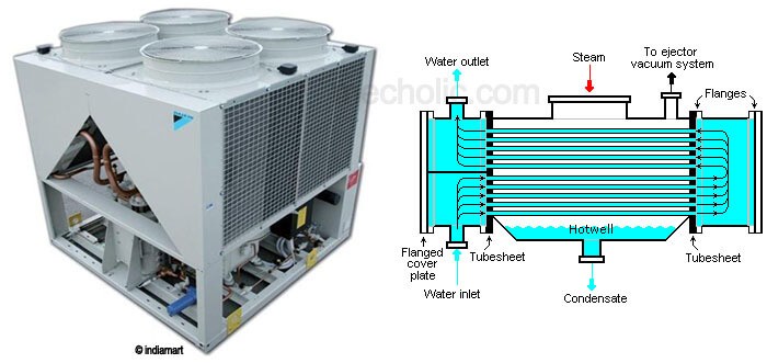
Figure 6: Shell and Tube type condenser

Steps required for the design calculation of Shell and Tube Condenser: Initially consider -
i. Condenser Type: Shell and Tube Condenser
ii. No of Tube Passes
iii. Velocity of Cooling water
iv. Condenser Purity Factor for water with chemical treatment = β
v. Tube Size
Steps in design Calculation:
Step 1: Find the heat duty of the condenser.
Step 2: Find the mass flow rate of cooling water.
Step 3: Find the overall heat transfer coefficient.
Step 4: Calculate the cooling surface area.
Step 5: Find the number of tubes with the help of the continuity equation.
Step 6: Find the approximate length of the tube.
Step 7: Find the accurate length of the tube depending on the heat transfer area required.
Step 8: Determine the diameter of the shell.
Step 9: Determine the pumping power.
Step 10: Determine the power of the cooling tower fan.
Figure 7: water-cooled condenser - shell and tube type

3. Evaporative Condenser: This is the third type of condenser; the design requirement may vary a little bit depending on the operation carried out in the condenser.
Figure 8: Evaporative Condenser
