So, a lot of you will know that a pet project of mine has been to adapt the old Apple Powermac G4 cube to take modern PC parts.

Powermac G4 Cube
I love the Cube and feel the look is timeless and elegant. The new Mac Pro is actually of a similar size, but somehow I don’t think that the design will be regarded with the same affection as the short run Cube (they were only made for a year).
One of my goals in making a kit for the Cube case was to allow a wide choice of hardware to be built into it. Not an easy task in itself as the interior of the metal ‘can’ of the Cube is only 174mm by 174mm across (and it has rounded corners which make things more difficult).
For a modern build most people will want to mount an ITX board into the case which in itself is 170mm by 170mm.
The challenge of the Cube is that the original ‘core’ is quite difficult to adapt for new hardware (though many have done it) and even more tricky to keep cool as there are only two faces that are not completely closed – top and bottom – and the original Cube really only had room for a 80 or 92mm base fan and had a difficult path for air to follow.
One other issue is that, because of the tight interior dimensions, no conversion was able to fit the rectangular IO plate. This plate is always offset to one side (because that is the way the ITX standard is written) and simply can’t be accommodated in Cube conversions.
So in the prototype of the laser hive kit I developed a bottom plate like this:
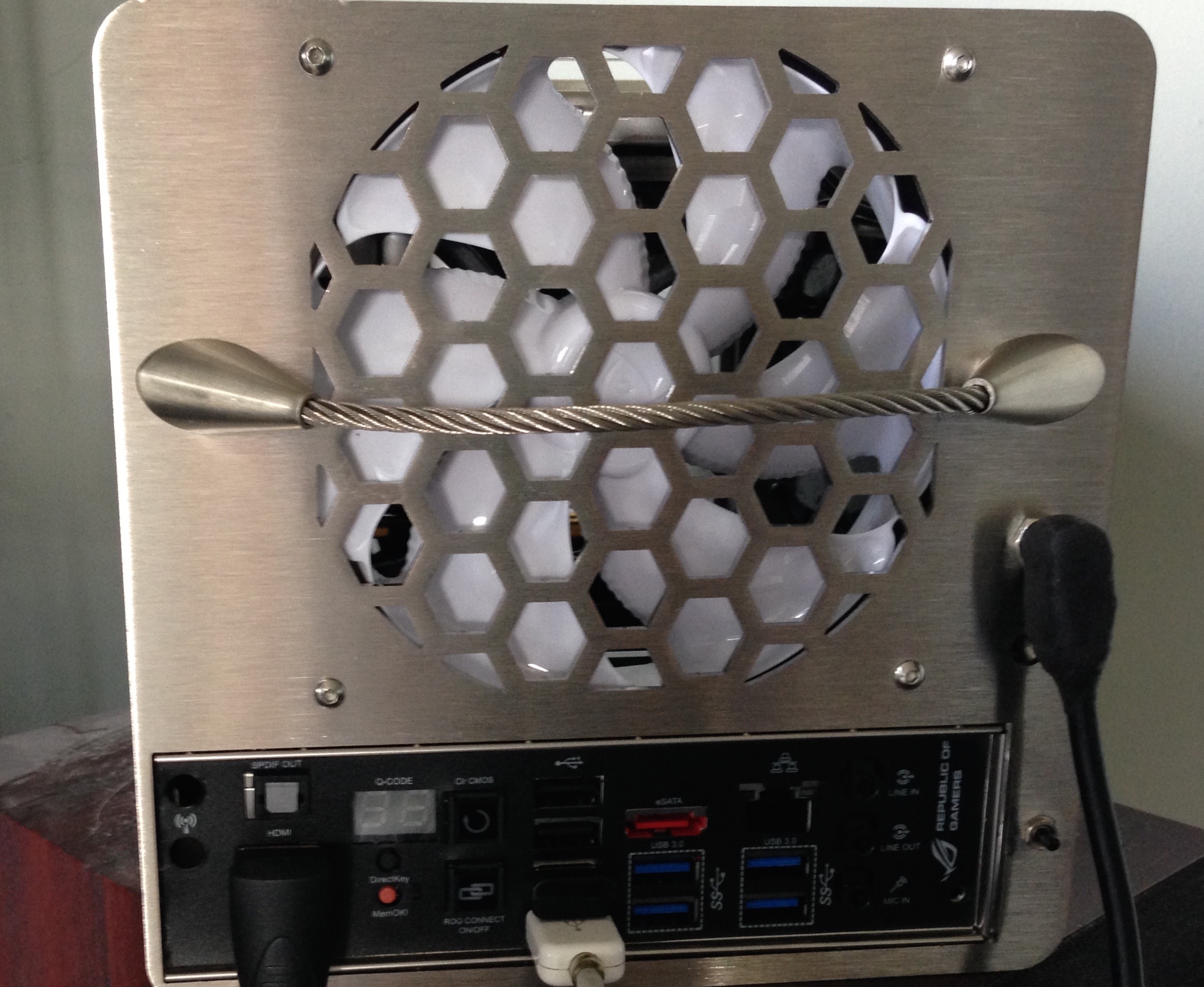
Prototype kit bottom face
Notice that the IO shield is very close to the side of the bottom plate. To fit an IO shield you do need to trim the left edge by removing the ‘folded’ part and this then is sufficient and should be fine for every ITX board to mount correctly.

Cutting the IO shield
In the prototype shown above I included a handle from wire mesh. This was needed as the connection method for the replacement core to fit into the metal ‘can’ was done using strong magnets. However, after much experimentation with different interior components I decided that magnets were just not reliable enough, so this meant that I could omit the handle. The production versions will have a similar style backplate made from the same 2mm thick brushed stainless steel but with only openings for the IO shield and the fan as well a hole for the power inlet – which is sized to take the inlet of a PicoPSU – and one more hole that can be used for anything. Perhaps you might use this extra hole for a momentary on/off switch (if you do not want a touch switch) or for a DVD drive eject switch or maybe for you to put an IR sensor through for remote control?
The design of the top plate of the kit is something that I have put a lot of time into.

Prototype Cube front
So in the prototype shown above, the opening is similar to the original Cube top plate, but different on both side edges (to accommodate magnets) and around where the touch sensor would be.
In the production version the top plate will be quite radically different again from the one shown above as the central opening will be larger, and extend a lot lower. The larger and lower cut means that if a PicoPSU is used then there is a greater chance (dependent on the board) of being able to fit it into the 24 pin ATX slot at the front of the mobo without issue. I say ‘greater’ chance because some boards and PicoPSUs may still push up too hard against the front plate and might push against any memory sticks stacked behind them – in which case you may need to mount your PicoPSU using a small extension cable – but I have tried to minimise the circumstances in which an extender might be needed.
Another difference between the prototype shown above and the final version is that the slot you see at the bottom of the plate will not be present on the production version. Instead there will be a finger of metal extending from the bottom centre point which will carry the touch sensor part – it will be similar in function and appearance to the arrangement tried in my latest all acrylic Cube:

Acrylic Cube prototype
You can see from the above picture that there is more room for the PSU board to comfortably fit even with a relatively cramped ITX board layout.
The side panels of the new Cube core will be similar to this:

Cube sides
If you look closely you will see that the bottom edges of the side panels are actually in line with the outer edges of the motherboard. This is so that once screws are added to secure the side panels and attach 2.5″ hard drives (to the inner side walls by means of the 4 holes around the panel mid point on each side) the total width from side to side stays within 174 mm including screw head height.
Once you realise this you will notice that the ITX motherboard itself does not have a ‘tray’ but is instead suspended underneath the core.The board is NOT however squashed inwardly at all as loads are carried by the metal structure and internal wall(s).
The internal walls I mention above are: (a) an inner cross piece that carries the 120 fan and which braces the two sides and holds them apart and (b) a shelf which in the Cube above is used for carrying a DVD drive, but in other variations can carry hard drives up to 3.5″ desktop drive size.
You will notice that one side wall has a large rectangular cut out. This is because on all ITX boards it seems that this side is used for SATA connections, fan sockets and other cabling so to have a cut away portion here lets you have easy access for plugging in and removing cables when the construction is complete. Also, for boards such as Maximus Impact variants a large ‘daughter board’ is present at that spot and would otherwise not fit in the Cube kit – providing the cut out means it can fit.
All of the walls and the ITX mobo are attached to one another using a series of modding cubes:

These are through threaded on 4 of their 6 sides and are 10mm square. This 10mm dimension is actually quite important to the Cube as when used as vertical standoffs (separated from the ITX motherboard surface by a suitable 3mm thick acrylic washer) the modding cubes set the side wall spacing as being at their ideal positions of 168mm apart from one another when measured between the inner wall surfaces.
In total up to 18 of these threaded modding cubes are used in the Cube kit.
A key feature provided by this construction method is that any one of the outer panels may be easily removed for access to change components whilst maintaining the integrity of the shell to make the change and then can be simply screwed back into position again. This removes a lot of the frustration and skinned knuckle joints normally associated with a Cube mod!
So there you have it, a taster of what the Cube kit will be like and how it will work. Once the production panels get here I will share them with you to show how it all works in final form. Be advised though, 4 out of 5 of the first production run have already had an interest on them expressed…..
Example configurations and extra notes:
All Cube kits will support: Rear fan 120mm of 15 to 25mm thickness. Standard ITX board. Up to 2 Drives mounted on interior side walls. Pico type PSU. Touch switch operation optional – as an alternative you may mount a simple push switch to the Cube base to turn it on.
With shelf: Adds room for 1 x 3.5″ desktop drive and 1 (or 2 with piggy back connection) 2.5″ drives/SSD. OR laptop type Optical drive plus 2.5″ drive.
When a shelf is fitted note that low profile (less than 8cm tall) coolers are preferred. When no shelf is fitted then coolers up to 14cm tall may be supported.
When no shelf is used there is the interesting possibility for fitment of 120 radiator based all in one coolers. I have tried this with an early Silverstone Tundra and it works, but please note that careful choice of components for such an arrangement is critical. Among this aspect note that the combined CPU plate/pump height will need to be as low as possible and you also should note that some pipe lengths on All In One water coolers may not tolerate being twisted into the small space necessary and might need cutting and replacing. So this type of configuration is definitely undertaken at the customers’ own risk!
If you wish to make no cuts to your original Cube case then I advise keeping a simple configuration and to use low profile RAM. High profile RAM sticks may require you to cut away some internal parts of the Cube ‘can’ – notably the areas where the original Cube handle would attach to.
A sheet of insulating material is provided with each kit to avoid the possibility of the underside of your motherboard from shorting out against the metal interior of the Cube ‘can’.